Table of Contents
Advertisement
Quick Links
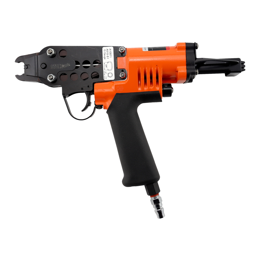
Paslode RINGfast
A515 Pneumatic
Ring Fastening Tool
Product Manual
WARNING
Before operating this tool, all operators should study this manual
to understand the hazards and operation of this tool.
Please keep these instructions with the tools for future reference.
Exclusively distributed by Whites Group Pty Ltd
www.whitesgroup.com.au
ABN 25 001 845 478
Advertisement
Table of Contents

Related Manuals for Paslode RINGfast A515


Summary of Contents for Paslode RINGfast A515
- Page 1 Paslode RINGfast A515 Pneumatic Ring Fastening Tool Product Manual WARNING Before operating this tool, all operators should study this manual to understand the hazards and operation of this tool. Please keep these instructions with the tools for future reference. Exclusively distributed by Whites Group Pty Ltd www.whitesgroup.com.au...
-
Page 2: Table Of Contents
Table of contents page Tool specifications............2 Safety instructions ............3 Lubrication and maintenance ........4 Loading the tool ..............5 Operating the tool ............6 Cleaning the tool .............7 Clearing a jam from the tool ........... 8 Trouble shooting .............9 Clinchers replacement ............ 17 Driver replacement ............18 Piston’s O-ring replacement ..........20 Valve’s O-ring replacement .......... -
Page 3: Tool Specifications
Tool specifications Part Number: A10870 Tool Description: Paslode RINGfast A515 Tool Dimensions: 336mm x 220mm x 89mm Length x Height x Width Weight (without C-Rings): 1.35Kg Air inlet…………………………………1/4” NPT Compressed air: Maximum permissible operating pressure…8KG/CM (110PSI) Recommended operating pressure ……5-7 KG/CM (70-100PSI) Air co nsumption ………………………………0.112M... -
Page 4: Safety Instructions
Safety instruction DANGER 1.Read this manual and understand all safety instructions before operating the tool. 2.Never use flammable gases as a power source for the tool. Use filtered, lubricated, regulated compressed air only. 3.Never use gasoline or other flammable liquids to clean the tool. 4.Do not exceed maximum permissible operating pressure of the tool (8kg/cM 5.Disconnect the tool from air supply before cleaning jams, servicing, adjusting,... -
Page 5: Lubrication And Maintenance
Disconnect the air supply from the tool before lubricating. Before each use turn the tool so the inlet is facing up and put one drop of Paslode pneumatic oil into air inlet. Never use detergent oil additives. Operate the tool briefly after adding oil. -
Page 6: Loading The Tool
Loading the tool Disconnect the air supply. Insert a stick of appropriate C-rings into the magazine (035) from back. Let the stick slide forward to the front of the magazine. Pull pusher (034) back and up to against the end of stick. -
Page 7: Operating The Tool
Operating the tool Protect your eyes and ears. Wear safety glasses with side shields. Wear hearing WARNING protection. Employers users responsible for ensuring the user or anyone near the tool wear this safety protection. To prevent accidental injuries: Never, place a WARNING hand or any other part of body in staple clinching area or adjustment window. -
Page 8: Cleaning The Tool
Cleaning the tool DANGER Never use gasoline or other flammable liquids to clean the tool. Vapors in the tool will ignite by a spark and cause the tool to explode and result in death or serious personal injury. 1. Disconnect the air supply from the tool. -
Page 9: Clearing A Jam From The Tool
Clearing a jam from the tool Disconnect the air supply. Move out remnant c-rings from magazine (035). Clearing jam using pliers. -
Page 10: Trouble Shooting
Trouble shooting Problem Cause Solution Inside diameter of ring Latch (014) worn Replace latch (014) too large after clinching Wrong latch used (014) Verify and replace latch (too short) (014) Latch spring broken (016) Replace latch spring (016) Wrong piston rod (026) Verify and replace piston rod (too short) (026) - Page 11 Problem Cause Solution Inside diameter of ring Defective rings: too large after clinching 1. Wire too hard Return sample of rings to 2. Rough surface your distributor to be tested 3. Cut-off burrs Inside diameter of ring Wrong clinchers (021 、 022) Verify and replace clinchers too small after clinching (021、022) Clinchers stops worn or...
- Page 12 Problem Cause Solution Ring tear drops instead Latch (014) worn Replace latch (014) of forming Verify and replace latch Wrong latch (014) (too (014) short) Replace latch spring (016) Latch spring (016) bent or broken (latch spring (016) must hold latch (014) tightly against end of side plate (015) and against clinchers (021、022))
- Page 13 Problem Cause Solution Rings jam Magazine (035) Magazine (035) 1. Damaged or bent 1.Replace magazine (035) (changes position of magazine shoe (027) 2. too many shims (ring 2.Replace magazine shoe passes under magazine (027) shoe (027) without raising magazine shoe; ring out of control) 3.
- Page 14 Problem Cause Solution Defective rings Rings jam 1. Burrs Return sample of rings to 2. Rings skewed on stick your distributor to be tested 3. Rings out of line on stick 4. Rings twisted 5. Rings not symmetrical 6. Rings strip flare at the ends Wrong wire gauge for Verify wire size...
- Page 15 Problem Cause Solution Ring spitting Air pressure too high Verify proper air pressure Spring (032) too loose Adjust spring (032) Magazine (035) Magazine (035) 1. Damaged or bent 1. Replace magazine (035) (change position of shoe (027)) 2. Replace magazine shoe 2.
- Page 16 Problem Cause Solution Ring spitting Build up of material in Remove build up of material clinchers (021、022) helix, (when using plated, aluminum or plastic coated rings) Snapping noise as ring Defective rings is being fed from 1.Burr on outside curve of Return sample of rings to magazine ring...
- Page 17 Problem Cause Solution Leaking when fighting Rear valve’s seat (006) is Adjust the position of rear not at the right position valve’s seat (006) (See page Worn O-ring (506) Replace O-ring (506) Worn O-ring (504) Replace O-ring (504) Worn O-ring (502) Replace O-ring (502) Worn O-ring (525) Replace O-ring (525)
-
Page 18: Clinchers Replacement
Replace clinchers Disconnect the air supply and move out remnant c-rings from magazine (035). Loosen Screw (516) and nut (515) with M5 Hex. Wrench key and M10 spanner. Take away screw(516), nut (515), washer (017), lash spring (016), clinchers (021,022) and bushings (013). Replace new clinchers (021,022) and bushings (013). -
Page 19: Driver Replacement
Replace Blade Disconnect the air supply and move out remnant c-rings from magazine (035). Take away Screw (512) with M3 Hex. Wrench key. Take away screw (501), cap (001) and packing (002) with M3 Hex. Wrench key. Take away screw (516), nut (515) washer (017), latch spring... - Page 20 Take away pin (024), roller (025) and blade (023). Replace blade (023).
-
Page 21: Piston's O-Ring Replacement
Replace piston’s O-ring Disconnect the air supply and move out remnant c-rings from magazine (035). Take away Screw (512) with M3 Hex. Wrench key. Take away screw (501), cap (001) and packing (002) with M3 Hex. Wrench key. Take away screw (516), nut (515) washer (017), latch spring... - Page 22 Take away pin (024), roller (025) and blade (023). Push piston rod (026) up. Take away nut (524) with M10 Spanner and pliers. Then, take away washer (038), piston (003) and piston rod (026). Replace piston’s O-ring (502).
-
Page 23: Valve's O-Ring Replacement
Replace valve’s O-ring Disconnect the air supply and move out remnant c-rings from magazine (035). Take away Screw (512) with M3 Hex. Wrench key. Take away screw (501), cap (001) and packing (002) with M3 Hex. Wrench key. Take away screw (516), nut (515) washer (017), latch spring... - Page 24 Loosen to screw (510) with M2 Hex. Wrench key. Loosen and take away throttle stem (018) font valve seat(019) with pliers. Take away screw (503) and deflector (005) with M3 Hex. Wrench key. Take away rear valve’s seat (006) and spring (007) with flat screw driver.
- Page 25 Reassemble font valve seat (019), let top of font valve seat (019) 0.8mm higher than body (004). Reassemble spring (007) and rear valve’s seat (006). Connect air supply. Reassemble throttle stem (018). leaking when shooting, then adjusting the position of font valve seat (019).
- Page 26 Replace pusher spring Disconnect the air supply and move out remnant c-rings from magazine (035). Take away screw (516) and nut (515) with M5 Hex. Wrench key and M10 Spanner. Take away screw (516), nut (515), washer (017), latch spring (016), clinchers (021,022) and bushing (013).
-
Page 27: Pusher's Spring Replacement
Take away screw (522) with M3 Hex. Wrench key. Take away screw (518) with M2.5 Hex. Wrench key. Take away spring pins (517) withΦ2.3mm rod and hammer. Replace pusher spring (032). - Page 30 Exclusively distributed by Whites Group Pty Ltd www.whitesgroup.com.au ABN 25 001 845 478...
Need help?
Do you have a question about the RINGfast A515 and is the answer not in the manual?
Questions and answers