Advertisement
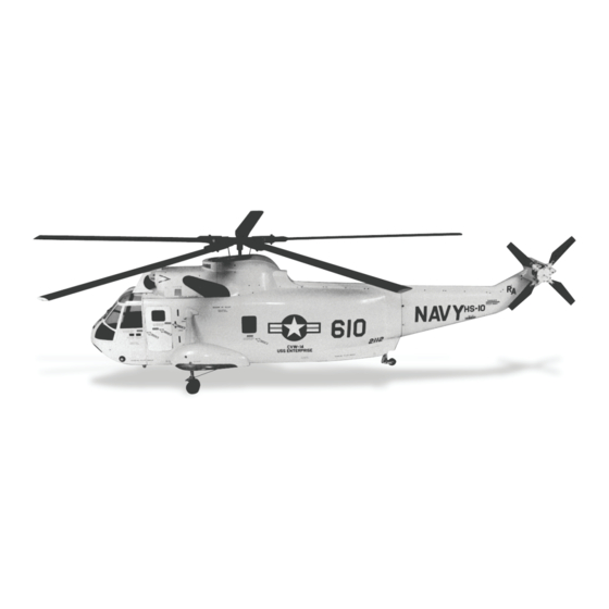
Sikorsky Sea King
Fuselage Instruction Manual
Century has designed a new Sikorsky S-61 Sea King. Changes to
full-size helicopter designs are a direct challenge to the modeler. To
its predecessor, the Century model Sea King fuselage has many tiny
details to catch your eye, and major detail features make a tremen-
dous difference to the overall impression.
SEA KING SPECIFICATIONS
Length: 54" Body nose to body tail.
Width: 18.5" Body left to right.
Height: 13" Body bottom to top.
Weight: 12-14 lbs. With full load of 60-90 size
Century Helicopter Products
mechanics and Radio equipment
Designed and Developed in the USA
Sept, 2002 All rights reserved.
Advertisement
Table of Contents

Related Manuals for Century Helicopter Products Sikorsky S-61 Sea King


Summary of Contents for Century Helicopter Products Sikorsky S-61 Sea King
- Page 1 Sikorsky Sea King Fuselage Instruction Manual Century has designed a new Sikorsky S-61 Sea King. Changes to full-size helicopter designs are a direct challenge to the modeler. To its predecessor, the Century model Sea King fuselage has many tiny details to catch your eye, and major detail features make a tremen- dous difference to the overall impression.
-
Page 2: Section One: Tail Drive & Installation
CN4004 Sea King Scale Fuselage Manual Warning The Sea King fuselage is designed to use Century’s flexible cable drive system, this requires that the mechanics installed use a wire drive tail shaft or can be modified from a shaft or torque tube drive system. A belt drive A belt drive A belt drive A belt drive... - Page 3 design is to use the existing vertical fin mounts on the tail gearbox to Photo #1 Photo #1 Photo #1 Photo #1 Photo #1 secure the tail gearbox to the wood former. Depending on the tail gearbox to be installed, additional mounting may need to be designed at the top of the gearbox (this is at your discretion).
- Page 4 If installing another tail gearbox other than Century’s, follow the example detailed above and make the required modifications to mount into the tail section. Step 5. Installing a flexible cable drive system Step 5. Installing a flexible cable drive system Step 5.
- Page 5 Step 10. To prepare to mount the tail wire Step 10. To prepare to mount the tail wire Step 10. To prepare to mount the tail wire Step 10. To prepare to mount the tail wire Step 10. To prepare to mount the tail wire To prepare to mount the tail wire strut for the tail wheel, match the wire strut to the plans and make a mark on the fuselage where the strut will exit the fuselage.
- Page 6 permanently bond the F15 and F16 former in place. Step 16a. Step 16a. Step 16a. Step 16a. Step 16a. For the Century tail gearbox, bond the F16 former onto the F15 former. Place the formers (still referred to as F15) into the cavity and reposition. Bond the brass housing and the rudder pushrod housing in place using slow CA, or Epoxy using the information collected in Step 15.
-
Page 7: Section Two: Wooden Substructure
glass. Note that the rudder servo no longer is required to be mounted directly behind the mechanics, the general rule is to make the rudder pushrod as short as possible to reduce slop in the control surface. The exact servo position is the modeler’s choice and is no longer detailed in these instructions. - Page 8 a jig saw, cut out these marked slots in the bottom of the F3 rail formers such photo #5 photo #5 photo #5 photo #5 photo #5 that the bottom of F1 fits flush with the bottom of the F3 rail edge. It is best to cut and fit one end at a time to get the best fit.
-
Page 9: Section Three: Main Fuselage Preparation
The substructure needs to be fuel proofed before it is permanently installed into the fuselage, using a fuel proof paint that matches your color scheme, paint all wood surfaces. Alternately, mixing rubbing alcohol with Epoxy can be used if you wish to preserve the nature wood look of the formers. Step 23i. - Page 10 Step 27. The sponson templates created are exact matches to the boss on the sponson. Using a pencil or a fine marker, trace the template onto the fuselage. Remove the template and the axle. Carefully sand or scrape through the gelcoat surface to the bare fiberglass, staying 1/8"...
- Page 11 Once the fuselage is painted, clean and wipe acetone (do not get any on the painted surface) on the inside surface of the window openings on the fuselage to be bonded. Using “Goop” or “R/C 56 windshield adhesive” commonly found in the local model-airplane hobby shop, apply an even coat to the edge of the windshield. Be careful not to Be careful not to Be careful not to Be careful not to...
-
Page 12: Section Four: Final Assembly
mechanics. Trim the flexible cable using the cutoff wheel on the moto-tool. Do not try to use side cutters to cut Do not try to use side cutters to cut Do not try to use side cutters to cut Do not try to use side cutters to cut Do not try to use side cutters to cut the cable as you will damage the cable. -
Page 13: Section Five: Painting
Having removed the pushrod mount from the Retract axle, insert the axle, making sure the pushrod hole aligns with the retract mechanism. Once the axle is past the F3 Rail former (photo #8), slide two F8 Round formers before the axle exits the other side. The axle pushrod can be reassembled photo #8 photo #8 photo #8... - Page 14 most pod and boom helicopters, there is no contest. This plastic material is virtually indestructible at the penalty of being virtually un-paintable without specialized and expensive automotive primers and paints. Consequently, there is also a very limited range of colors available. The reason you are reading this page is that you want to fly a model that looks and holds all the prestige of a real helicopter.
- Page 15 nents together or any other item to it - wood or metal to the fiberglass. Step 48. Step 48. Step 48. Step 48. Step 48. Once the detail parts have been built into the sub assemblies are ready to paint, use a filler in sections that have gaps or slight surface imperfections, occasionally there are voids (air bubbles in the resin) that occur near the surface that need to be filled.
Need help?
Do you have a question about the Sikorsky S-61 Sea King and is the answer not in the manual?
Questions and answers