Table of Contents
Advertisement
Quick Links
Bedienung und installation
operation and installation
utilisation et installation
Bediening en installatie
oBsluha a instalace
oBsluha a inštalácia
Эксплуатация и монтаж
Obsługa i instalacja
geschlossener Warmwasser-Wandspeicher | sealed, unvented wall mounted dhW
cylinder | chauffe-eau mural ecs sous pression | gesloten warmwaterboiler voor
wandbevestiging | tlakový nástěnný zásobník teplé vody | uzavretý nástenný
zásobník na teplú vodu | настенный накопительный водонагреватель закрытого типа |
ciśnieniowy ogrzewacz wody
» psh 30 trend
» psh 50 trend
» psh 80 trend
» psh 100 trend
» psh 120 trend
» psh 150 trend
» psh 200 trend
Advertisement
Table of Contents
Troubleshooting

Related Manuals for STIEBEL ELTRON psh 50 trend


Summary of Contents for STIEBEL ELTRON psh 50 trend
- Page 1 | tlakový nástěnný zásobník teplé vody | uzavretý nástenný zásobník na teplú vodu | настенный накопительный водонагреватель закрытого типа | ciśnieniowy ogrzewacz wody » psh 30 trend » psh 50 trend » psh 80 trend » psh 100 trend » psh 120 trend »...
-
Page 2: Table Of Contents
ConTenTS SPeCiAL inforMATion SPECIAL INFORMATION OPERATION General information _______________________________________ 16 - The appliance may be used by children aged 8 safety instructions ���������������������������������������������� 16 and up and persons with reduced physical, sen- Other symbols in this documentation ���������������������� 17 Units of measurement ����������������������������������������� 17 sory or mental capabilities or a lack of experience and know-how provided that they are supervised Safety ________________________________________________________ 17... -
Page 3: Special Information
SPecial informaTion oPeraTion - Install a type-tested safety valve in the cold water supply line. For this bear in mind that, depending on the static pressure, you may also need a pres- sure reducing valve. General information - Size the drain so that water can drain off unim- The chapters "Operation"... -
Page 4: Other Symbols In This Documentation
oPerATion Safety Other symbols in this documentation General safety instructions WARNING Burns Note During operation, the tap and safety valve can reach General information is identified by the symbol shown temperatures in excess of 60 °C. on the left. f Read these texts carefully. There is a risk of scalding at outlet temperatures in ex- cess of 43 °C. -
Page 5: Settings
oPerATion Settings Settings Cleaning, care and maintenance f Have the electrical safety of the appliance and the function of The temperature can be freely adjusted. the safety valve regularly checked by a qualiied contractor. f Have the protective anode initially checked by a qualiied contractor after the irst year. -
Page 6: Installation
inSTALLATion Safety inSTALLATion Preparations Installation site The appliance is designed to be permanently wall-mounted to a Safety solid surface. Ensure the wall offers adequate load bearing ca- pacity. Only a qualiied contractor should carry out installation, commis- sioning, maintenance and repair of the appliance. There should be a suitable drain near the appliance to drain off the expansion water. -
Page 7: Installation
inSTALLATion installation 10.2 Power supply 10. Installation WARNING Electrocution 10.1 Water connection Carry out all electrical connection and installation work in accordance with relevant regulations. Material losses Before any work on the appliance, disconnect all poles Carry out all water connection and installation work in from the power supply. -
Page 8: Commissioning
inSTALLATion commissioning 11. Commissioning 13. Troubleshooting 11.1 Commissioning Note The high limit safety cut-out can respond at temperatures below –15 °C. The appliance may be subjected to these Note temperatures during storage or transport. Fill the appliance with water prior to electrical connec- tion. -
Page 9: Maintenance
inSTALLATion Maintenance 14.5 Anti-corrosion protection 14. Maintenance Ensure that while carrying out maintenance work the anti-corro- WARNING Electrocution sion protection (560 Ω) is not damaged or removed. Reinsert the Carry out all electrical connection and installation work anti-corrosion protection correctly after replacement. in accordance with relevant regulations. -
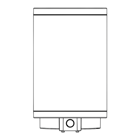
Page 10: Specification
inSTALLATion Speciication 15. Specification 15.1 Dimensions and connections PSH 30 PSH 50 PSH 80 PSH 100 PSH 120 PSH 150 PSH 200 Trend Trend Trend Trend Trend Trend Trend Appliance Height 1015 1170 1400 1705 Appliance Depth Appliance Diameter Entry electrical cables Threaded fitting M20x1.5 M20x1.5... -
Page 11: Wiring Diagram
inSTALLATion Speciication Wall mounting bracket 15.3 Heat-up diagrams The heat-up time depends on the cylinder capacity, cold water 30 - 50 l inlet temperature and heating output. Graph assumes 15 °C cold water inlet temperature: 80 - 200 l X Temperature setting [°C] Y Heat-up time [h] 15.2 Wiring diagram 1 150 l... -
Page 12: Data Table
inSTALLATion | wArrAnTy | environMenT And recycLing Speciication 15.5 Data table PSH 30 PSH 50 PSH 80 PSH 100 PSH 120 PSH 150 PSH 200 Trend Trend Trend Trend Trend Trend Trend 232080 232081 232082 232083 232084 232085 232086 hydraulic data nominal capacity Amount of mixed water 40 °C (15 °C/65 °C) Electrical data...
Need help?
Do you have a question about the psh 50 trend and is the answer not in the manual?
Questions and answers