Rayburn 680KCD C Installation Instructions Manual

Rayburn 680KCD C Installation Instructions Manual

Floor standing combined cooker and central heating boiler.
Hide thumbs Also See for 680KCD C:

Advertisement

REMEMBER, when replacing a part on this appliance, use only spare parts that you can be assured conform to the
safety and performance specification that we require. Do not use reconditioned or copy parts that have not been clearly
authorised by AGA.
PLEASE READ THESE INSTRUCTIONS BEFORE INSTALLING THIS APPLIANCE
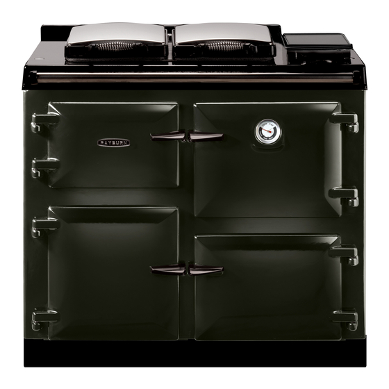
680KCD C/F
780KCD C/F
DESN 516260
nstallation
nstructions
For use in GB & IE
DESN 516828
12/15 EINS 516257

Advertisement

Table of Contents
loading
Need help?

Need help?

Do you have a question about the 680KCD C and is the answer not in the manual?

Questions and answers

Subscribe to Our Youtube Channel

Summary of Contents for Rayburn 680KCD C

  • Page 1 680KCD C/F 780KCD C/F DESN 516260 DESN 516828 nstallation nstructions REMEMBER, when replacing a part on this appliance, use only spare parts that you can be assured conform to the safety and performance specification that we require. Do not use reconditioned or copy parts that have not been clearly authorised by AGA.
  • Page 2: Table Of Contents

    Contents SECTION CONTENTS PAGE CONSUMER PROTECTION HEALTH & SAFETY APPLIANCE SPECIFICATION - 680KCD C/F APPLIANCE SPECIFICATION - 780KCD C/F TECHNICAL DATA SITE REQUIREMENTS INTRODUCTION REGULATIONS LOCATION OIL PIPE LINE OIL STORAGE FLUE SYSTEM TYPICAL CHIMNEY INSTALLATION TYPICAL EXTERNAL FLUE SYSTEM...
  • Page 3: Consumer Protection

    Consumer Protection As responsible manufacturers we take care to make sure that our products are designed and constructed to meet the required standards when properly installed and used. IMPORTANT NOTICE: PLEASE READ THE ACCOMPANYING WARRANTY Any alteration that is not approved by AGA could invalidate the approval of the appliance, operation of the warranty and could affect your statutory rights.
  • Page 4 RAYBURN 680KCD C/F ONLY FLUE PIPE RETURN PIPE CONDENSE OUTLET FLOW PIPE CONNECTION LH SIDE FRONT VIEW VIEW RH SIDE VIEW ELECTRIC PLAN VIEW CONNECTIONS PLEASE NOTE: IT IS ADVISABLE TO CHECK THE ACTUAL SIZE/WIDTH OF YOUR APPLIANCE BEFORE FINALLY FIXING ANY KITCHEN UNITS SINCE ENAMELLED CAST Fig.
  • Page 5 RAYBURN 780KCD C/F ONLY RH SIDE VIEW ELECTRIC CONNECTIONS PLEASE NOTE: IT IS ADVISABLE TO CHECK THE ACTUAL SIZE/WIDTH OF YOUR APPLIANCE BEFORE FINALLY FIXING ANY KITCHEN UNITS SINCE ENAMELLED CAST Fig. 1B DESN 516829 IRON CAN VARY IN SIZE.
  • Page 6: Technical Data

    Technical Data 680/780KCD C/F BOILER BURNER COOKER BURNER BURNER NOZZLE (US g/h) 0.65 @ 80°EH 0.35 @ 80°S OIL PRESSURE Bar (psi) 8.5 (125) 10 (145) OIL BURNING RATE cc/m 42.5 HEAT INPUT kW 15.0 BOILER OUTPUT kW...
  • Page 7: Site Requirements

    Site requirements INTRODUCTION REGULATIONS The Rayburn is a floor standing combined cooker and THIS APPLIANCE IS A CONTROLLED SERVICE BY central heating boiler. It gives independent operation of DEFINITION AND REQUIRES EITHER FITMENT space heating, domestic hot water and cooking.
  • Page 8: Location

    Site requirements LOCATION Space around the flue pipes passing through walls or Appliance Hearth: The surface temperature of the floor floors should be sealed against the passage of smoke below the appliance does not exceed 100°C. The and flame. A fire stop valve and plate must be provided constructional hearth described in Section J does not where the flue passes through a ceiling.
  • Page 9: Oil Pipe Line

    This must be contained within the appliance. GRAVITY SINGLE FEED PIPE SYSTEM Fig. 3 - Rayburn 680KCD C/F shown DESN 516267 A...
  • Page 10: Flue System

    Site requirements FLUE SYSTEM The flue system must be installed with the regulations in Chimney Termination force. All chimneys should terminate at least 600mm above the roof level in accordance with current Building Regulations Maximum flue gas temperature 250°C and statutory requirements as outlined in BS 5410: Part 1, (Both burners on) BS 6461: Part 1 and BS 7566 Parts 1 to 4.
  • Page 11: Typical Chimney Installation

    Site requirements Site requirements TYPICAL CHIMNEY INSTALLATION 125 T/FLEX SCREW TYPE TERMINAL PART NO. 4048125 125 T/FLEX LW TOP PLATE PART NO. 4002125 125 T/FLEX LW TOP CLAMP PART NO. 4003125 BRICK CHIMNEY TECNO FLEX SYSTEM ALL PARTS AVAILABLE THROUGH RECOMMENDED SCHIEDEL RITE-VENT 125 DIA TECNOFLEX STAINLESS STEEL STOCKISTS...
  • Page 12: Typical External Flue System

    Site requirements TYPICAL EXTERNAL FLUE SYSTEM NOTE: FOR PART NO’s FOR ECO ICID FLUE SYSTEM GO TO www.schiedel.co.uk STRUCTURAL WALL BAND WITH EXTENSION ECO ICID STAINLESS/STEEL TWIN WALL INSULATED CHIMNEY SYSTEM. ALL PARTS 45° BEND AVAILABLE THROUGH SCHIEDEL RITE-VENT STOCKISTS (SEE WALL BAND RECOMMENDED STOCKIST LIST IN BACK OF INSTRUCTION...
  • Page 13: Air Supply

    Site requirements AIR SUPPLY The appliance can only be installed in a room which The extract fan should then be run at its maximum meets the ventilation regulations in force. But, in any setting. The oil fired heating appliance should be event the room must have a permanent vent of minimum observed to operate satisfactorily both before and after free air area, see below:...
  • Page 14: Water Circulation System

    Site requirements WATER CIRCULATION SYSTEM HEATING CONTROLS Flow and return pipework between cooker and zone Independent temperature controls with time switch control valves must be 28mm diameter minimum. are recommended for providing temperature comfort from radiators. Space and water heating should be in accordance with the relevant recommendations of BS 5410: Part 1.
  • Page 15: Electrical Supply

    Site requirements ELECTRICAL SUPPLY Wiring external to the appliance must be installed in accordance with current National Wiring Regulations and any local regulations which apply. The appliance is supplied for 230 Volt ~ 50 Hz 270W a fuse rating of 3 amps.
  • Page 16: Boxes

    Site requirements Rayburn 600/700 Wiring 111MB for independent Satronic boxes 680KCD C/F 780KCD C/F Fig. 6...
  • Page 17: Installation Requirements

    Installation requirements CLEARANCES 25mm The appliance is floor mounted. The space in which the appliance is to be fitted must have the following minimum dimensions. Between wall or unit and LH side of appliance - 4mm top plate Between wall or unit and RH side of appliance - 4mm top plate SHOULD THE WALL PROJECT BEYOND THE FRONT OF THE APPLIANCE, IT MUST BE INCREASED TO...
  • Page 18: Site Location

    4. Connect and terminate the flue system in accordance with the regulations in force. SEE FIG. 10 1. Remove top LH door (Rayburn 680KCD C/F only) and facia glass. Remove 2 fixing screws from control panel chassis and hinge open.
  • Page 19: Baffles

    Installation requirements ALL BAFFLES MUST BE STACKED IN PLACE AS DIAGRAM ABOVE Fig. 12 DESN 515919...
  • Page 20: Oil Connection

    1. Place a sheet on the floor in front of the cooker to act as a working area. 2. Remove lower LH door (Rayburn 680KCD C/F only) and burner aperture cover and store in a safe place. 3. Unscrew jubilee clip and remove flexi air intake pipe from burner.
  • Page 21: Commissioning Instructions

    NOTE: PLEASE REMOVE PLASTIC PROTECTION ON DOOR LININGS. 1. Open the burner access door. Remove door and put in a safe place. (Rayburn 680KCD C/F only). 2. Remove 4 inner panel securing screws and remove panel. 3. Remove the 3 plinth securing screws and remove plinth.
  • Page 22: Terminal Strip Connections

    Commissioning Instructions TERMINAL STRIP CONNECTIONS The switch LIVE must be connected to the programmer or room stat. The system pump and mains should be connected as shown in Fig. 18. Fig. 18 DESN 514865 ELECTRICAL CHECK Checks to ensure electrical safety should be carried out by a competent person.
  • Page 23: Fit Pressure Gauge

    Commissioning Instructions FIT PRESSURE GAUGE SEE FIG. 19 Remove the bleed screw from the manifold and fit an oil pressure gauge with R 1/8 connection to check the pump output pressure. Switch on the Electricity Set the boiler burner thermostat to maximum. The boiler burner should run on pre-purge for 7-15 seconds, with the ignition spark energised.
  • Page 24: Set Combustion Air - Boiler

    Commissioning Instructions SET COMBUSTION AIR - BOILER To access the boiler burner flueways:- 1. Remove top LH door (Rayburn 680KCD C/F only) and facia glass. Remove 2 fixing screws from control panel chassis and hinge open. 2. Remove plug from sampling point. (See Fig. 22).
  • Page 25: Set Combustion Air - Cooker

    Replace the countersunk headed screw on completion ensuring that it will not interfere with any pots and pans placed on the hotplate. When satisfied with combustion check, refit burner door inner panel. Fig. 24 - Rayburn 680KCD C/F shown DESN 516264...
  • Page 26: Ancillary Controls Check

    Commissioning Instructions ANCILLARY CONTROLS CHECK INSTRUCT THE USER Before leaving the site, check the operation of the 1. Advise the User of the precautions to prevent damage programmer and the control thermostat are working to the heating system and to the building in the event correctly and are capable of controlling the burners of the heating system being inoperative during frost correctly.
  • Page 27: Sealed System Requirements

    Sealed System SEALED SYSTEM REQUIREMENTS g. Mains Connection There shall be no connection to mains water supply or SEE FIG. 25 to the water storage cistern supplying domestic hot water, even though a non-return valve may be fitted, a. The installation must comply with the requirements of without the approval of the local water authority.
  • Page 28 SHOULD THE PUMP BE FITTED TO THE RETURN SIDE, THEN THE PRESSURE GAUGE AND EXPANSION VESSEL ARE FITTED ADJACENT TO THE SUCTION SIDE OF THE PUMP. THE SAFETY VALVE REMAINS AS SHOWN ON THE FLOW PIPE. Fig. 25 - Rayburn 680KCD C/F shown...
  • Page 29: Condensate Disposal

    Provision must be made for the safe and effective removal of the condensate. Rayburn boilers are supplied with a condensate trap to provide the required 75mm water seal in the condensate Condensate can be disposed either internally - into an discharge pipe from the boiler.
  • Page 30: Condensate Soakaway

    Installation Instructions Fig. 27 DESN 515917 Care should be taken when siting the trap such that the overflow outlet is readily visible and that any condensate overflowing from the outlet cannot cause either a hazard to persons or damage to surrounding property or equipment.
  • Page 31 Recommended Schiedel Rite-vent Suppliers CHIMFLUE WELHAM GREEN UNIT 10 ALPHA BUSINESS PARK NEW VENT SOLUTIONS TRAVELLERS CLOSE UNIT B6 WELHAM GREEN DENMARK STREET HATFIELD POSSILPARK HERTFORDSHIRE GLASGOW AL9 7NT LANARKSHIRE G22 6DB TEL: 01707 266244 TEL: 0141 336 7742 SPECFLUE LIMITED CAST TEC UNIT 8 CURZON ROAD EAST SIDE...
  • Page 36 With AGA Rangemaster’s policy of continuous product improvement, the Company reserves the right to change specifications and make modifications to the appliance described at any time. Manufactured by AGA Rangemaster Station Road Ketley Telford Shropshire TF1 5AQ England Tel: 0845 815 2020 www.rayburn-web.co.uk www.agacookshop.co.uk...

This manual is also suitable for:

680kcd f780kcd c780kcd f660680699k ... Show all

Table of Contents