MV Agusta Brutale 800 Owner's Manual
Hide thumbs
Also See for Brutale 800:
- User manual (89 pages) ,
- Maintenance manual (80 pages) ,
- Workshop manual (472 pages)
Table of Contents
Advertisement
Available languages
Available languages
Quick Links
Advertisement
Chapters
Table of Contents

Related Manuals for MV Agusta Brutale 800


Summary of Contents for MV Agusta Brutale 800
- Page 2 Owner’s Manual...
- Page 3 © 2012 This document may not, in whole or in part, be reproduced without prior consent, in writing, from MV Agusta Motor S.p.A. Part No. 8000B7954 - Edition No. 1 Printed in October 2012...
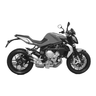
- Page 4 Dear Customer, Brutale 800 We wish to thank you for your preference and congratulate you on purchasing your new Brutale 800 Your choice is a reward for the passionate effort our technicians have put into giving the function- al and aesthetic characteristics that place it above the finest motorcycles currently available on the market, mak- ing it an exclusive and sought-after item.
-
Page 5: Table Of Contents
CONTENTS chap. Subjects covered page chap. Subjects covered page GENERAL INFORMATION 2.1.14. Customer satisfaction Purpose of this manual 2.1.15 Suggestions against theft General safety information Safety labels - Location Symbols Safety - Visual and acoustic signals Warranty Booklet and Service Coupons CONTROLS AND INSTRUMENTS Identification data Location of controls and instruments... - Page 6 CONTENTS chap. Subjects covered page chap. Subjects covered page 4.4.3 SPEED LIMITER mode 5.6.1. Rebound damper (rear suspension) 4.4.4 TC mode 5.6.2. Compression damper (rear suspension) 4.4.5 Chronometer Headlight adjustment 4.4.6 QUICK SHIFT mode MAINTENANCE 4.4.7 Clock setting Tables of scheduled maintenance and checks 124 4.4.8 How to select the mapping of the control unit Tools and accessories supplied...
-
Page 7: Chap. Subjects Covered
CONTENTS chap. Subjects covered page chap. Subjects covered page TECHNICAL INFORMATION 6.13.2 Manufacturer’s warranty coverage Motorcycle overview 6.13.3 Owner’s warranty responsibilities 8.1.1 Front brake system 6.14 Limited warranty on emission control 8.1.2 Rear brake system system (for U.S.A. only) 8.1.3 Engine lubrication 6.14.1 Coverage 8.1.4... - Page 8 INDEX Accessories Chain – installation – check Adjustments – lubrication – front brake lever Chronometer – front suspension Cleaning the motorcycle – headlight Competitions – list Controls and instruments, location – rear suspension – rearview mirrors Coolant – table – level, check –...
- Page 9 INDEX Emissions Identification data – control system Idle speed, check – control system warranty Ignition switch and steering lock – periodic check Instruments and warning lights Engine – lubrication Kickstand – oil level, check – oil level, topping up – serial number Levels –...
- Page 10 INDEX Tires, check Purpose of manual – puncturing – replacement Rearview mirrors Tools and accessories supplied – adjustment Topping up Refuelling – coolant Replacing parts, general information – engine oil Troubleshooting flow chart – electrical equipment Safety – engine – labels, location Turn indicators –...
-
Page 11: General Information
GENERAL INFORMATION 1.1. Purpose of this manual Carefully read, understand and follow the instructions given in this manual. It is an essential part of the motorcycle as is intended to familiarize you with the controls, characteristics and features of the motorcycle. Keep it in a safe place for future reference. -
Page 12: Symbols
Information on operations that are sug- could result in death or serious injury. gested to be performed by your autho- rized MV Agusta dealer. CAUTION: Indicates a potentially haz- ardous situation which, if not avoided, The following symbol is used to provide further may result in minor or moderate injury. -
Page 13: Warranty Booklet And Service Coupons
Dealer. One of the copies must be delivered to the Customer, one must be kept by the Dealer and one must be sent to Motovan Corporation - MV Agusta Canada. The dealer must always fill in the service coupons. They must be kept by the Customer and by the Dealer. -
Page 14: Identification Data
GENERAL INFORMATION 2) engine serial number 1) vehicle identification number 1.5. Identification data 1) vehicle identification number 2) engine serial number Motorcycle identification We recommend writing down the main numbers The motorcycle is identified by the vehicle identi- in the spaces provided below. fication number. - Page 15 ZCG J F G L T X Y V 000000 Manufacturer’s Letter Code Motorcycle Type Progressive vehicle number The vehicle identification number must be provided each time you need to contact the MV Agusta Technical Assistance Service, in order to guarantee the traceability of your motorcycle. - 14 -...
- Page 16 GENERAL INFORMATION Motorcycle key identification A key is supplied in duplicate for both the ignition and all the locks. Keep the duplicate in a safe place. When placing orders for spare keys, you may be requi- red to provide the key identification number. It is advised to note this number in the following space: KEY Nr.: - 15 -...
- Page 17 GENERAL INFORMATION - 16 -...
- Page 18 GENERAL INFORMATION Bodywork parts reference colors Bodywork parts are painted with the following reference colors, according to the corresponding motorcy- cle color combination (see page 20): 1. - Rear side fairing, right-hand; 5. - Fuel tank: 2. - Rear side fairing, left-hand: Color code A: Color code A: Pearly Red...
- Page 19 GENERAL INFORMATION - 18 -...
- Page 20 GENERAL INFORMATION Frame parts reference colors Frame parts are painted with the following reference colours, according to the corresponding motorcy- cle colour combination (see page 20): 3. - Right-hand frame plate; 1. - Frame: 4. - Left-hand frame plate; 5. - Rear swingarm: Color codes A-C-D: Quasar Black Mica Black...
- Page 21 GENERAL INFORMATION Identification of motorcycle color combination The color code must be mentioned when ordering body spares. It can be read on the right side of the fuel tank. In order to get to the colour code label, it is necessary to remove the saddle.
-
Page 22: Safety Information
MV Agusta S.p.A. If NHTSA For U.S.A. only: receives similar complaints, it may open an inves- MV Agusta S.p.A. warrants that, at the time of tigation, and if it finds that a safety defect exists in sale, the exhaust system conformed to all applic- a group of vehicles, it may order a recall and rem- able U.S. -
Page 23: Note On Tampering
SAFETY INFORMATION 2.1.3. NOTE ON TAMPERING 3. Poor maintenance. 4. The replacement of any movable parts of the Tampering with the noise control system is pro- vehicle or of any intake or exhaust compo- hibited. In particular, federal law prohibits the fol- nents with parts or components other than lowing acts: those prescribed by the manufacturer. -
Page 24: Information On The Emission Control System
In addition, the fuel tanks are manufactured highly toxic. MV Agusta uses a sequential multi- specifically to limit the permeation of fuel vapours point electronic injection system and other meth-... -
Page 25: Safe Riding
In addition to obtaining the to others. Avoid wearing dark colored clothing necessary driver’s license, MV Agusta strongly because that makes it more difficult for others to recommends that you take a certified course see you on the roadway, even in the daytime. - Page 26 Never attach any key ring or other object to your motorcycle to a MV Agusta dealer. Do not your ignition key, as they could interfere with your ride until any damage is repaired by an authorized ability to steer your motorcycle.
-
Page 27: Maintaining Your Motorcycle
Section 6. make any noise, immediately stop riding your motorcycle. Have your motorcycle professionally b. Maintenance, repair and service of your inspected and repaired by an MV Agusta dealer, motorcycle require specialized knowledge, tools as necessary. and experience. General mechanical aptitude may not be sufficient to properly maintain, repair or service your motorcycle. -
Page 28: Before You Ride
SAFETY INFORMATION 2.1.7. BEFORE YOU RIDE a. Your motorcycle, like all products, may wear d. Be sure that your tires are inflated to the cor- over time. Before each ride, make sure you rect pressure and that there is no damage what- perform all pre-ride checks as stated in Section soever in the tread or sidewall of the tire. -
Page 29: While You Ride
SAFETY INFORMATION 2.1.8. WHILE YOU RIDE a. Your motorcycle is a very high performance d. When the motorcycle is being ridden at high vehicle. Do not confuse the enhanced capabili- speed, gearing down several times in rapid suc- ties of your motorcycle with your own capabili- cession can cause the engine to overspeed. - Page 30 SAFETY INFORMATION g. Sudden gusts of wind can cause you to lose you do ride in these conditions, travel at low control of your motorcycle. Reduce your speed speed and avoid abrupt maneuvers. and exercise extreme caution when you are over- l.
- Page 31 MV Agusta or hidden, latent p. Never exceed the stated speed limit. By avoi- or obvious defects in the product, and agrees to ding speeding, you reduce the risk of accidents.
-
Page 32: After You Ride
SAFETY INFORMATION 2.1.9. AFTER YOU RIDE WARNING d. Never park your motorcycle on soft or a. The engine, exhaust pipes and other uneven surfaces because that could components will be hot after riding and cause the motorcycle to topple over, present a risk of burn injury to adults or resulting in injury or death to a bystander. -
Page 33: Installing Accessories
Always select serious personal injury or even death. your accessories with careful consultation with your MV Agusta dealer to insure that the most Verify that the installed accessories do not appropriate accessories are selected. It is essen-... -
Page 34: Vehicle Load
Your motorcycle is designed for use by the rider death. If any accessory results in an unnatural and only one passenger. To use the vehicle in riding position, immediately see your MV Agusta complete safety, it is essential that the following dealer before riding your motorcycle. - Page 35 SAFETY INFORMATION WARNING WARNING NEVER OVERLOAD YOUR MOTORCY- Never carry any incorrectly secured CLE! Driving an overloaded motorcycle object on your motorcycle, which might can cause damage to the tires, brakes or shift or fall away during riding that could other structural components of your affect the motorcycle stability.
-
Page 36: Modifications
(e.g. alteration and/or removal of components) as these modifi- MV Agusta has designed a number of special cations can make the vehicle unsafe components for use in competitions and/or sport- and/or illegal. MV Agusta is not responsi- ing events. -
Page 37: Suggestions Against Theft
SAFETY INFORMATION Motovan Corporation - MV Agusta Canada (1391 2.1.15. SUGGESTIONS AGAINST THEFT Gay Lussac, Boucherville, Quebec J4B 7K1, 1. Every time you park your motorcycle, operate Canada - Phone no.: 450-449-3903 / Fax no.: the steering lock and remove the ignition key 450-449-7773) wants you to be aware of its par- (see §... -
Page 38: Safety Labels - Location
SAFETY INFORMATION 2.2. Safety Labels - Location 1 - Rearview mirrors 2 - Documentation warning 3 - Fuel warning 4 - Battery warning 5 - Emission control 6 - Information on emission control 7 - Information on gas emissions, exhaust silencers 8 - Information on gas emissions, exhaust manifolds 9 - Certification label... - Page 39 SAFETY INFORMATION 1. ADHESIVE LABEL – REARVIEW MIRRORS OBJECTS IN MIRROR ARE CLOSER THAN THEY APPEAR 2. ADHESIVE LABEL – DOCUMENTATION WARNING - 38 -...
- Page 40 SAFETY INFORMATION 3. ADHESIVE LABEL – FUEL WARNING 4. ADHESIVE LABEL – BATTERY WARNING - 39 -...
- Page 41 SAFETY INFORMATION 5. ADHESIVE LABEL – EMISSION CONTROL M O TO R C Y C L E N O I S E E M I S S I O N C O N T R O L I N F O R M AT I O N THIS 2013 MVA43B0800 MOTORCYCLE, MEETS US EPA NOISE EMISSION REQUIREMENT OF 80 dBA AT 6380 RPM BY THE FEDERAL TEST PROCEDURE.
- Page 42 SAFETY INFORMATION 6. ADHESIVE LABEL – INFORMATION ON ENGINE DISPLACEMENT : 798 cc EMISSION CONTROL ENGINE FAMILY : DMVAC.798 MHA ENGINE EXHAUST CONTROL SYSTEM: SFI + TWC + H02S THIS VEHICLE CONFORMS TO US EPA AND CALIFORNIA REGULATIONS APPLICABLE TO 2013 MODEL YEAR NEW MOTORCYCLES AND IS CERTIFIED 0.8 g/km HC+NOx, 12 g/km CO EXHAUST EMISSION STANDARD IN CALIFORNIA OIL : SAE 5 W 40 TYPE : SYNTHETIC A.P.I.
- Page 43 8. STAMPING ON EXHAUST MANIFOLDS – MOTORCYCLE EXHAUST SYSTEM NOISE EMISSION EMISSION INFORMATION CONTROL INFORMATION. THIS MV AGUSTA EXHAUST SYSTEM, 8000B7008 MEETS US EPA NOISE EMISSION REQUIREMENT OF 80 dBA FOR THE FOLLOWING MOTORCYCLES: MVA43B0675 AND MVA43B0800. INSTALLATION OF THIS EXHAUST SYSTEM ON MOTORCYCLE...
- Page 44 SAFETY INFORMATION 9. ADHESIVE LABEL – MANUFACTURED BY: DATE : CERTIFICATION LABEL Motor S.p.A. FABRIQUÉ PAR: VARESE - ITALY TYPE OF VEHICLE / TYPE DE VÉHICULE: MOTORCYCLE / MC GVWR/PNBV 803 lbs 364 kg VIN/NIV: GAWR/PNBE F 353 lbs 160 kg R 551 lbs 250 kg USA: THIS VEHICLE CONFORMS TO ALL APPLICABLE FEDERAL MOTOR VEHICLE SAFETY STANDARDS IN EFFECT ON THE DATE OF MANUFACTURE SHOWN ABOVE.
- Page 45 SAFETY INFORMATION 11. ADHESIVE LABEL – REAR SHOCK ABSORBER W A R N I N G CONTAINS HIGHLY COMPRESSED GAS USE ONLY PERFECTLY DRY NITROGEN GAS OTHER GASES MAY CAUSE EXPLOSION DO NOT INCINERATE REFER TO OWNER’S MANUAL FOR REGULATING GAS 12.
-
Page 46: Safety - Visual And Acoustic Signals
SAFETY INFORMATION 2.3. Safety - Visual and acoustic signals Before each ride, it is essential to verify the operation of the visual and acoustic signals. Horn (§3.3.) Parking lights, low Rear side reflector and high beams (§3.3.) Turn indicators (§3.3.) Parking light (§3.3.) and brake light (lights up operating the brakes) Rear side reflector... -
Page 47: Controls And Instruments
CONTROLS AND INSTRUMENTS 3.1. Location of controls and instruments Half handlebar electrical controls, left side (§3.3.) Ignition switch and steering lock (§3.5.) Instruments and warning lights (§3.7.) Left side Right side Fuel tank cap (§4.5.) Half handlebar electrical controls, right side (§3.4.) Throttle twist grip (§3.4.) - 46 -... - Page 48 CONTROLS AND INSTRUMENTS Front brake lever (§5.1.) Clutch lever (§5.1.) Rearview mirrors (§5.1.) Passenger footrest Passenger footrest Passenger handhold Passenger handhold Rear brake lever (§5.1.) Rider footrest Rider footrest Kickstand (§3.2.) Gear lever (§3.6. and §5.1.) - 47 -...
-
Page 49: Kickstand
CONTROLS AND INSTRUMENTS 3.2. Kickstand The kickstand is equipped with a safe- ty switch that prevents motorcycle operation while the stand is down. If the rider attempts to engage the gears while the engine is running and the stand is down, the safety switch automatically turns off the engine by cutting the current supply. -
Page 50: Handlebar Controls, Left Side
CONTROLS AND INSTRUMENTS 3.3. Handlebar controls, left side Clutch lever Move towards/away from the handgrip to release/engage the clutch. High beam flasher button Press the button repeatedly. Low/high beam button Button not pressed in : low beam Button pressed in : high beam Horn button Press to operate the warning horn. - Page 51 CONTROLS AND INSTRUMENTS High beam flasher button It is used to attract the attention of other road users in case of danger. When the high beam is on, the function is inactive. Low/high beam button Under normal conditions, the low beam is on. The high beam can be switched on by pressing the but- ton when allowed by the traffic and road conditions.
-
Page 52: Handlebar Controls, Right Side
CONTROLS AND INSTRUMENTS 3.4. Handlebar controls, right side Front brake lever Pull to the lever to apply the front brake. Throttle twist grip Rotate counterclockwise to increase engine speed. Engine stop switch Stops the engine and prevents it from being restarted. Engine start button Starts the engine. - Page 53 CONTROLS AND INSTRUMENTS Engine stop switch It is used to switch off the engine in an emergency. The ignition circuit is disabled, preventing the engine from being restarted. To be able to restart the engine, return the switch to its original position. DANGER! If the throttle of your motorcycle sticks, you must use the engine stop switch to stop the delivery of power from the engine.
- Page 54 WARNING If your motorcycle has toppled over or has been involved in an accident, have the working of the throttle control checked by a MV Agusta authorized center before restarting. Front brake lever It controls a hydraulic circuit that operates the front wheel braking system.
-
Page 55: Ignition Switch And Steering Lock
CONTROLS AND INSTRUMENTS 3.5. Ignition switch and steering lock WARNING: Never attach a ring or any other object to the ignition key as they may hinder the steering action. Failure to observe this warning can lead to loss of control of the motor- cycle, resulting in an accident, personal injury or death. - Page 56 CONTROLS AND INSTRUMENTS OFF position All electrical circuits are deactivated. The key can be removed. ON position All electrical circuits are activated. The instruments and warning lights perform the self-diagnostic cycle. The engine can be started. The key cannot be removed. CAUTION Do not leave the key on the ON position for a long time when the engine is not running, in...
- Page 57 CONTROLS AND INSTRUMENTS LOCK position Turn the handlebar to the left. Press the key in gently while rotating it to the LOCK position. All electrical circuits are deactivated and the steering is locked. The key can be removed. Right side Left side - 56 -...
-
Page 58: Gear Lever
The “Quick Shift” system is not avail- tions which can compromise the stability able when you change gear with the clutch lever of the vehicle. MV Agusta recommends pressed or at a speed lower than 30 km/h, nor to operate the clutch lever in these cir- when shifting into lower gears. -
Page 59: Instruments And Warning Lights
CONTROLS AND INSTRUMENTS 3.7. Instruments and warning lights The instruments and warning lights are activated by turning the ignition switch to the ON position. After a preliminary check (approx. 7 seconds) the displayed information reflects the current general condition of the motorcycle. Tachometer display Warning lights (§3.7.1.) -
Page 60: Warning Lights
Lights up when the alternator does not supply Headlights (blue) enough current to charge the battery. It turns on when the headlights are on. If the indicator comes on while riding, contact a MV Agusta authorized service centre. - 59 -... -
Page 61: Multifunction Display
If it Trip counter 1, “TRIP 1” needs to be filled up, contact a MV Agusta licensed It displays the length of a trip; from 0 to 999.9 (Km or miles) service centre (see § 3.8). If the warning light turns Trip counter 2, “TRIP 2”... -
Page 62: Operation
OPERATION 4.1. Using the motorcycle This section provides the basic information needed to correctly operate the motorcycle: – Break-in ( § 4.2. ) – Starting the engine ( § 4.3. ) – Selecting and setting the display functions ( § 4.4. ) –... -
Page 63: Break-In
OPERATION Break-in CAUTION MAX 5500-6000 rpm Failure to observe the indications provided below can reduce performance and shorten the life of the motorcycle. Break-in is generally considered to apply only to the engine. In fact, it should be regarded as an essential phase for other important parts such as the tires, the brakes and the drive chain. - Page 64 OPERATION 500 to 1000 km (300 to 600 mi) Avoid low or high engine speeds and vary your speed frequently. Do not exceed the engine speed shown in 8000-9000 rpm the figure. 1000 to 2500 km (600 to 1600 mi) Higher engine performance can be demanded, but it is advisable not to exceed the engine speed shown in the MAX ...
-
Page 65: Starting The Engine
OPERATION 4.3. Starting the engine WARNING Starting the engine in a closed place can be dan- gerous. Exhaust emissions contain carbon monoxide, a colorless and odorless gas that can lead to serious harm or even death when inhaled. Only start the engine outdoor, in the open air. As you turn the ignition switch to the ON position, the instruments and the warning lights will go through the self-diagnostic cycle;... - Page 66 OPERATION If the self-diagnostic cycle detects a fault in the vehi- cle, the display shows the warning alert shown in the picture. In particular, this message highlights the vehicle part or device on which the fault has been detected. Press “OK” button to access to “RUN” mode. WARNING If a fault is detected on the vehicle, do not start engine and contact an authorized MV...
- Page 67 OPERATION Engine start procedure START button Press the start button without turning the throttle twist grip. As soon as the engine starts, release the button. CAUTION • Do not press the start button for longer than 5 consecutive seconds, in order to avoid dam- age to the electrical equipment.
-
Page 68: Selecting And Setting The Display Functions
OPERATION 4.4. Selecting and setting the display functions Some of the main measurements of the instruments may be changed. The available options include: - Select an operating mode: “RUN” (Odometer) “SPEED LIMITER” “TC” (Traction control) “CHRONO” (Chronometer) “QUICK SHIFT” * “CLOCK”... -
Page 69: Selecting The Display Functions
OPERATION 4.4.1. Selecting the display functions The following settings may be changed on the display: • “RUN” (Odometer) • “SPEED LIMITER” • “TC” (Traction control) • “CHRONO” (Chronometer) • “QUICK SHIFT” * • “CLOCK” (Clock) To display the operating modes, press “SET”... -
Page 70: Speed Limiter Mode
OPERATION “RUN” mode In addition to the speedometer, the display shows the following functions (see §4.4.2.): • Total odometer “TOTAL” • Trip counter 1 “TRIP 1” As an alternative: • Total odometer “TOTAL” • Trip counter 2 “TRIP 2” “SPEED LIMITER” mode This mode adjusts the maximum value of the vehicle speed to your driving requirements (see §4.4.3.). -
Page 71: Tc Mode
OPERATION “TC” Mode This Mode adjusts the engine traction control level to your driving requirements (see §4.4.4.). “CHRONO” Mode This mode turns on the Chronometer and saves the recorded information (see §4.4.5.). The following is displayed: • Chronometer Current lap “CURRENT LAP”... -
Page 72: Quick Shift Mode
OPERATION “QUICK SHIFT” mode * This mode allows to turn off or on the “quick shift” func- tion of the gear change (see §4.4.6.). (*): This function is present only on certain models; available in aftermarket on all models “CLOCK” Mode The present function enables to change the time (hours and minutes) reported on the dashboard (see §4.4.7.). -
Page 73: Trip Reset
OPERATION 4.4.2. Trip reset To reset “TRIP 1” and “TRIP 2”, proceed as follows. WARNING The display modes may be changed or set when the engine is off, the gear in neutral, the motorbike stationary with your feet on the ground. - Page 74 OPERATION Press the “OK” key for less than three seconds until the partial speedometer 2 function (“TRIP 2”) appears on the display. By pressing the “OK” key for more than three sec- onds, the “TRIP 2” value will be reset to zero. - 73 -...
- Page 75 OPERATION 4.4.3. “SPEED LIMITER” mode When starting the engine, the “SPEED LIMITER” func- tion is disabled. In order to activate it, it is necessary to perform the following operations: Press “SET” in order to access to “SPEED LIMI- TER” mode. The maximum speed value shown on the display (equal to the current speed of the vehicle) starts blinking.
- Page 76 OPERATION Press “OK” for over three seconds to confirm the selected maximum speed value. The displayed digit stops blinking and the display returns to “RUN” mode. On the other hand, if you press “SET” for over three seconds, the “SPEED LIMITER” function is disabled. The display shows the “OFF”...
- Page 77 OPERATION 4.4.4. “TC” Mode Press “SET” in order to access to “TC” mode, then press “OK” for less than three seconds until “TC LEVEL” appears. The current traction control level is the same as the one shown on the display. NOTE The traction control level may be changed or set even during the use of the vehicle.
-
Page 78: Chronometer
OPERATION 4.4.5. Chronometer Lap time recording Turn on the chronometer (“CHRONO” mode) to record the time taken to cover a lap. Press the headlight button to start recording the time. The colon that separates the minutes from the seconds and from the tenths of a second will start blink- ing. - Page 79 OPERATION Press the headlight button again to record the time taken to cover the 1st lap. At the same time, the instru- ment starts recording the time taken to cover the sec- ond lap. The time measurement for the first lap is stored in the memory and is visualised on the display for ten sec- onds, after which the time measurement for the follow- ing lap appears.
- Page 80 OPERATION Data display Once all times have been recorded, they may be displayed. Access the “CHRONO” mode; the time of the fastest lap (“BEST LAP”) and the time of the last lap (“LAST LAP”) appears on the display. WARNING The display modes may be changed or set when the engine is off, the gear must be in neutral, the motorbike must be stationary with your feet on the ground.
- Page 81 OPERATION By repeatedly pressing the key of the flashing high beam headlight, all the times previously acquired start- ing from the last lap memorised can be displayed in sequence. Once all the data have been displayed, press the “SET” key to return to the “LAPS VIEW” mode and then to the following mode.
- Page 82 OPERATION How to delete data To delete the saved data, proceed as follows: WARNING The display modes may be changed or set when the engine is off, the gear in neutral, the motorbike stationary with your feet on the ground. Do not change the display while dri- ving.
- Page 83 OPERATION Now, press “OK” for over three seconds to delete the value. Otherwise, press “SET” for less than three sec- onds to stop the deletion procedure. Subsequently, by pressing the flashing high beam headlight key followed by the “OK” key for more than three seconds, all the previously acquired times can be cancelled.
- Page 84 OPERATION Resetting of best lap time: Access the “CHRONO” mode and press the “SET” key for less than three sec- onds until the words “BEST LAP RESET” appear on the display. Press the “OK” key for less than three seconds; the value of the fastest last lap time memorised will start flashing.
- Page 85 OPERATION Now, press “OK” for over three seconds to delete the value. Otherwise, press “SET” for less than three seconds to stop the deletion procedure. Once all the data have been cancelled, press the “SET” key to exit the “BEST LAP RESET” mode and then pass to the following mode.
- Page 86 OPERATION Press the “OK” key for less than three seconds; the display will ask you to confirm cancellation of all the data present in the memory. By pressing the “OK” key for more than three sec- onds, all the previously acquired times will be cancelled. By pressing the “SET”...
- Page 87 OPERATION 4.4.6. “QUICK SHIFT” mode * Press “SET” in order to access to “QUICK SHIFT” mode. The display shows the current activation state of the “quick shift” function of the gear change. WARNING The display modes may be changed or set when the engine is off, the gear in neutral, the motorbike stationary with your feet on the ground.
-
Page 88: Clock Setting
OPERATION 4.4.7. Clock settings To carry out clock settings, press the "SET" button until viewing the "CLOCK SETTING" caption. WARNING The display modes may be changed or set when the engine is off, the gear in neutral, the motorbike stationary with your feet on the ground. - Page 89 OPERATION After having carried out the hour digit setting, the dashboard automatically switches to the minute digit setting. The minute digit begins to flash. By pressing the "OK" button for less than three seconds, the minute digit is increased by going to the following numeric value.
-
Page 90: How To Select The Mapping Of The Control Unit
OPERATION 4.4.8. How to select the mapping of the control unit On the Brutale 800 model is it possible to select diffe- rent control unit mappings which allow to obtain variable power and performance characteristics based on the type of vehicle use. - Page 91 OPERATION Setting of “Custom” mapping Press the start button when the engine is switched on until selecting the mapping “C” of the control unit (“Custom” mapping). WARNING The “Custom” mapping setting operations must be performed when the the gear is in neutral and the motorbike stationary with your feet on the ground.
- Page 92 OPERATION Press “SET” for less than three seconds. The display shows the current setting for throttle control sensitivity. Press “OK” for less than three seconds; the displayed setting will start flashing. By repeatedly pressing “OK” for less than three seconds, the following settings can be displayed in sequence: •...
- Page 93 OPERATION Press “OK” for more than three seconds; the new setting will be confirmed. The displayed caption stops flashing and after a few seconds the display returns to “GAS SENSITIVITY” mode. It is now possible to pro- ceed with the setting of the following parameter. Maximum engine torque: Press “OK”...
- Page 94 OPERATION Press “SET” for less than three seconds. The display shows the current setting for maximum engine torque. Press “OK” for less than three seconds; the displayed setting will start flashing. By repeatedly pressing “OK” for less than three seconds, the following settings can be displayed in sequence: •...
- Page 95 OPERATION Press “OK” for more than three seconds; the new setting will be confirmed. The displayed caption stops flashing and after a few seconds the display returns to “MAX ENGINE TORQUE” mode. Engine brake: Press “OK” for less than three seconds until “ENGINE BRAKE”...
- Page 96 OPERATION Press “SET” for less than three seconds. The display shows the current setting for engine brake. Press “OK” for less than three seconds; the displayed setting will start flashing. By repeatedly pressing “OK” for less than three seconds, the following settings can be displayed in sequence: •...
- Page 97 OPERATION Press “OK” for more than three seconds; the new setting will be confirmed. The displayed caption stops flashing and after a few seconds the display returns to “ENGINE BRAKE” mode. Engine response: Press “OK” for less than three seconds until “ENGINE RESPONSE” appears. - 96 -...
- Page 98 OPERATION Press “SET” for less than three seconds. The display shows the current setting for engine response. Press “OK” for less than three seconds; the displayed setting will start flashing. By repeatedly pressing “OK” for less than three seconds, the following settings can be displayed in sequence: •...
- Page 99 OPERATION Press “OK” for more than three seconds; the new setting will be confirmed. The displayed caption stops flashing and after a few seconds the display returns to “ENGINE RESPONSE” mode. Engine RPM limiter: Press “OK” for less than three seconds until “RPM LIMITER”...
- Page 100 OPERATION Press “SET” for less than three seconds. The display shows the current setting for engine RPM limi- ter. Press “OK” for less than three seconds; the displayed setting will start flashing. By repeatedly pressing “OK” for less than three seconds, the following settings can be displayed in sequence: •...
- Page 101 OPERATION Press “OK” for more than three seconds; the new setting will be confirmed. The displayed caption stops flashing and after a few seconds the display returns to “RPM LIMITER” mode. Press “OK” for less than three seconds until the display switches to the “RUN”...
-
Page 102: Warning/Malfunction Alerts
Press “OK” button to access to “RUN” mode. The direction indicator emergency lights begin to flash. WARNING If a fault is detected on the vehicle when the engine is off, do not start engine and contact an authorized MV Agusta centre. - 101 -... - Page 103 WARNING If a fault is detected during riding, stop the vehicle and contact an authorized MV Agusta centre. After the vehicle is stopped, the display shows the warning message highlighting the vehicle part or device on which the fault has been detected.
- Page 104 If the coolant temperature is high, stop the motorbike and check the coolant level. If it needs to be filled up, contact a MV Agusta licensed service centre (see § 3.8). If the war- ning alert appears even if the level is adequa- te, stop driving and contact a MV Agusta licensed service centre.
-
Page 105: Refuelling
OPERATION 4.5. Refuelling WARNING: Before opening fuel cap, switch off the engine, stop smoking, and keep away from flames, sparks and heat sources. Failure to observe this warning can lead to a fire, resulting in an accident, personal injury or death. - Page 106 OPERATION Lift the tank cap and operate the refuelling. WARNING: Never over fill the fuel tank. Overfilling may cause the fuel to overflow as a result of the expansion due to the heat from the engine or to exposure to sunlight. Fuel spills can catch fire.
-
Page 107: Glove Compartment
OPERATION 4.6. Glove compartment Insert the key into the lock. Rotate the key anticlockwise while slightly pushing the saddle. Lift the saddle and remove it as shown in the picture. In order to reassemble the above mentioned part, you must perform the following operations: •... -
Page 108: Parking The Motorcycle
OPERATION 4.7. Parking the motorcycle Using the kickstand WARNING • Park your motorcycle only on firm, level ground. Parking the bike on soft ground can allow the kickstand to dig in, and the motor- cycle can fall over resulting in an accident, personal injury or death. - Page 109 If you notice a malfunction of the kickstand switch, have it repaired by your MV Agusta dealer before using the motorcycle.
- Page 110 OPERATION Using the rear stand Insert the stand pin into the rear wheel axle hole on the left side of the motorcycle. Rest the stand on the ground and, pressing down on the stand, lift the vehicle until it reaches a stable condition.
-
Page 111: Checks To Be Performed Before Riding
OPERATION 4.8. Checks to be performed before riding Engine start button / stop switch Check operation (§ 3.4). WARNING: A motorcycle can be in good Clutch lever running order and then become unex- Check fluid level (§ 6.9). pectedly unreliable if it was unused for a Check for fluid leakage. - Page 112 OPERATION WARNING Drive chain Check adjustment and lubrication (§ 6.11). If any component does not pass this Coolant pre-riding inspection, have it repaired Check level (§ 6.6). before operating the motorcycle. Failure Check for leakage. to do so could result in an accident, per- Engine oil sonal injury or death.
-
Page 113: Adjustments
ADJUSTMENTS 5.1. List of adjustments There are many adjustments that can significantly improve the ergonomics, geometry and safety of the motorcycle. WARNING: Many of these adjustments require specialized knowledge, tools and experience. General mechanical aptitude and tools may not be sufficient to properly inspect, adjust, service or repair your motorcycle. - Page 114 ADJUSTMENTS (D) Rearview mirror adjustment (§5.4.) (F) Front suspension adjustment (§5.5.) (A) Front brake lever adjustment (§5.3.) (H) Headlight adjustment (§5.7.) (C) Rear brake lever adjustment (§5.2.) - 113 -...
- Page 115 ADJUSTMENTS (D) Rearview mirror adjustment (§5.4.) (G) Rear suspension adjustment (§5.6.) (B) Gear lever adjustment (§5.2.) (E) Drive chain adjustment (§5.2.) - 114 -...
-
Page 116: Table Of Adjustments
- compression damper (§5.6.2.) bar. If this screw needs to be tightened, contact your MV Agusta dealer. H - Headlight adjustment: To adjust the range of the light beam to the geometry of the motorcycle E - Drive chain adjustment: To ensure safe and effective transmission of power. -
Page 117: Adjusting The Front Brake Lever
ADJUSTMENTS 5.3. Adjusting the front brake lever WARNING Never perform the adjustment while rid- ing. Rotate the lever adjust to change its position. Clockwise: the lever moves closer to the handle. Counter-clockwise: the lever moves away from the handle. - 116 -... -
Page 118: Adjusting The Rearview Mirrors
ADJUSTMENTS 5.4. Adjusting the rearview mirrors WARNING Never perform the adjustment while riding. Rotate the rearview mirror body to adjust its position in the four directions. WARNING Check the rearview mirrors adjustment every time you use your motorcycle. - 117 -... -
Page 119: Adjusting The Front Suspension
ADJUSTMENTS 5.5. Adjusting the front suspension Rebound damper NOTE: The adjustment of the suspen- sions must be preferably performed with the fuel tank full. 5.5.1. Spring preload (front suspension) See the table in the enclosed sheet for spring pre- load adjustment. Refer to the number of turns from the fully counterclockwise position. -
Page 120: Rebound Damper (Front Suspension)
ADJUSTMENTS 5.5.2. Rebound damper (front suspension) 5.5.3. Compression damper (front suspension) See the table in the enclosed sheet for rebound See the table in the enclosed sheet for rebound damping adjustment. Refer to the number of turns damping adjustment. Refer to the number of turns from the fully clockwise position. -
Page 121: Adjusting The Rear Suspension
ADJUSTMENTS 5.6. Adjusting the rear suspension WARNING The rear shock absorber contains high- ly compressed gas. Do not try to open or disassemble it in any way. Failure to heed this warning may lead to an explo- sion, resulting in an accident, personal injury or death. -
Page 122: Rebound Damper (Rear Suspension)
ADJUSTMENTS 5.6.1. Rebound damper (rear suspension) 5.6.2. Compression damper (rear suspension) See the table attached to this manual for rebound See the table attached to this manual for compres- damping adjustment. Refer to the number of turns sion damping adjustment. Refer to the number of from the fully clockwise position. -
Page 123: Headlight Adjustment
ADJUSTMENTS 5.7. Headlight adjustment Place the vehicle at a distance of 10 m (32.8 ft) from a vertical wall. Make sure that the motorcycle is placed on an even horizontal surface, and that the headlight’s optical axis is perpendicular to the wall. The vehicle must be held in an upright position. Measure the “X” distance between the headlight center and the ground surface, then trace a small cross on the wall at the same height. - Page 124 ADJUSTMENTS The headlight adjustment can be performed by rotating the screw shown in the picture. Rotate clockwise to incline the headlight downwards, counterclockwise to incline it upwards. It can be tilted up to an angle of ±4° from the stan- dard position.
-
Page 125: Maintenance
MAINTENANCE 6.1. Tables of scheduled maintenance and checks The periodic checks and maintenance operations that are required to keep your motorcycle safe and in perfect running order are shown in the following tables. WARNING: Many of these services and maintenance tasks require specialized knowledge, tools and expe- rience. - Page 126 If your motorcycle is involved in an accident, have all it thoroughly inspected by an autho- rized MV Agusta dealer. Failure to heed this warning and operating a motorcycle, which is unsafe, could lead to serious injuries or even death.
- Page 127 Every time vehicle is used Engine oil Renew At least once a year Replace Engine oil filter (Use only MV Agusta Every time engine oil is changed genuine spare oil filters) Check / Restore level Every time vehicle is used Coolant...
- Page 128 MAINTENANCE Tables of scheduled maintenance 1000 6000 12000 18000 24000 30000 36000 km (mi) covered (600) (3800) (7500) (11200) (14900) (18600) (22400) Pre- Service coupon delivery ESCRIPTION PERATION Check / Replace Timing movable shoe Replace Every time timing chain is replaced Timing chain stretcher Check / Replace Check / Replace...
- Page 129 MAINTENANCE Tables of scheduled maintenance 1000 6000 12000 18000 24000 30000 36000 km (mi) covered (600) (3800) (7500) (11200) (14900) (18600) (22400) Pre- Service coupon delivery ESCRIPTION PERATION Check operation Every time vehicle is used Clean lever / master cyl. Every 500 ÷...
- Page 130 MAINTENANCE Tables of scheduled maintenance 1000 6000 12000 18000 24000 30000 36000 km (mi) covered (600) (3800) (7500) (11200) (14900) (18600) (22400) Pre- Service coupon delivery ESCRIPTION PERATION Flexible controls and Check / Adjust transmissions Check Every 1000 Km (600 mi) Lubricate Every 1000 Km (600 mi) and after riding under the rain Drive chain...
- Page 131 MAINTENANCE Tables of scheduled maintenance 1000 6000 12000 18000 24000 30000 36000 km (mi) covered (600) (3800) (7500) (11200) (14900) (18600) (22400) Pre- Service coupon delivery ESCRIPTION PERATION Rear sprocket spring drive Check / Replace Check Steering bearings Lubricate Check pressure Every time vehicle is used;...
- Page 132 MAINTENANCE Tables of scheduled maintenance 1000 6000 12000 18000 24000 30000 36000 km (mi) covered (600) (3800) (7500) (11200) (14900) (18600) (22400) Pre- Service coupon delivery ESCRIPTION PERATION Check operation Every time vehicle is used Sidestand Check operation Check operation Every time vehicle is used Clean contact area Every 500 ÷...
- Page 133 MAINTENANCE Tables of scheduled maintenance 1000 6000 12000 18000 24000 30000 36000 km (mi) covered (600) (3800) (7500) (11200) (14900) (18600) (22400) Pre- Service coupon delivery ESCRIPTION PERATION Battery connections Check and clean Electrical equipment Check operation Check operation Every time vehicle is used Instrument panel Check operation Check operation /...
- Page 134 In order to highlight symbols importance, remember the following information: Information on operations that can be carried out by the user. Information on operations that are suggested to be performed by your authorized MV Agusta dealer. The “ ” symbol points out the requirement to use a tool or a special equipment in order to correctly perform the described operation.
-
Page 135: Tools And Accessories Supplied
MAINTENANCE 6.2. Tools and accessories supplied Under the passenger seat you can find the following Tools: 2 Allen wrenches (2,5 mm - 4 mm hexagon); 1 spanner for rear wheel eccentric with extension; 1 fuse puller. Inside the fuse box are also provided the following spare fuses (see §6.16.1): 2 fuses (10A);... -
Page 136: Table Of Lubricants And Fluids
D.I.D. CHAIN LUBE – : MV Agusta suggests to refer directly to its authorized dealers in order to purchase the recommended product. The eni i-Ride moto2 5W/40 engine oil has been expressly produced for the Brutale motor- cycle engine. If the above described lubricant is not available, MV... -
Page 137: Checking The Engine Oil Level
MAINTENANCE 6.4. Checking the engine oil level Check the oil level while the engine is not running, and has been allowed to cool down for at least ten minutes after a ride. The check must be performed after placing the motor- cycle in an upright position on a horizontal surface. -
Page 138: Topping Up The Engine Oil Level
MAINTENANCE 6.4.1. Topping up the engine oil level Remove the oil filler plug. Pour an appropriate amount of engine oil of the recommended type. Never exceed the MAX level mark. At the end of the operation, place back the oil filler plug. CAUTION To avoid clutch sliding and damage to the engine, never add chemical addi-... - Page 139 MAINTENANCE WARNING New or used engine oil can be danger- • Keep new or used engine oil out of ous. Engine oil is highly toxic for people reach of children and domestic animals. and domestic animals. Avoid ingestion • While topping up the engine oil, wear and contact.
-
Page 140: Checking The Coolant Level
MAINTENANCE 6.5. Checking the coolant level Check the coolant level after the engine has been shut off for at least fifteen minutes after riding. If you attempt to check the coolant level while the engine is still warm, you will get an erroneous level indication. WARNING: Never attempt to remove the coo- lant cap when the engine is hot. -
Page 141: Topping Up The Coolant Level
MAINTENANCE 6.5.1. Topping up the coolant level Unscrew and remove the coolant filler cap. Using a syringe, top up with the recommended coolant (see §6.3). WARNING The cooling system is under pressure. Always very carefully remove the coolant filler cap. Never attempt to remove the coolant filler cap until the motor- cycle has completely cooled to... - Page 142 See your MV Agusta dealer. personal injury. CAUTION WARNING Do not spill coolant on any part of the Coolant is a highly toxic fluid.
-
Page 143: Checking The Wear Of The Brake Pads
If the pads have worn to near the wear limit, have both pads replaced by your MV Agusta dealer. Never replace just one pad, the pads must always be replaced in pairs. -
Page 144: Checking The Brake Fluid Level
MAINTENANCE Rear brake fluid reservoir Front brake fluid reservoir 6.7. Checking the brake fluid level WARNING The level of the brake fluid decreases as the Before riding, always check the braking brake pads wear down. Ensure that the fluid level system according to the instructions is always between the MAX and MIN marks. - Page 145 MIN decrease of the braking efficiency. This mark, the braking system must be over- could increase the risk of accidents, with hauled by an authorized MV Agusta subsequent serious injury or even death. dealer. WARNING...
-
Page 146: Checking And Replacing The Tires
MAINTENANCE 6.8. Checking and replacing the tires WARNING Before using the motorcycle, always check the pressure and wear of the tires. The tire air pressure must be checked and adjusted on cold tires. Checking the air pressure of each tire is an essential requirement to ensure driving safety. - Page 147 1/8 inch (3 mm). low speed until you reach the nearest Verify the absence of crevices at the bottom of the MV Agusta dealer and have the tire tread design and fissures on the tire sidewall. replaced. With a provisionally repaired Moreover, verify the absence of nails and glass tire, never exceed 60 km/h (35 mph).
-
Page 148: Replacement
MAINTENANCE • Do not use sealing fluids to repair a tires. Otherwise, the tire bead could not punctured tire. These products can properly settle down on the wheel rim, adversely affect the material of the tire leading to the deflation of the tire and layers, as well as hide the minor damages the loss of control of the vehicle. - Page 149 MAINTENANCE Rear wheel disassembling CAUTION If you have the rear tire replaced by a tire dealer that is not an authori- zed MV Agusta dealer, make sure that the following tools are used during disassembly and reassem- bly: Polygonal nut •...
- Page 150 Every time you replace a tire or a rim, you must have a wheel balancing deflation of the tire and the loss of con- performed by an authorized MV Agusta trol of the motorcycle resulting in an accident, personal injury or death.
-
Page 151: Checking And Lubricating The Drive Chain
If the distance is greater than 116 mm (4.56 sprocket your fingers and hand in.), have the chain adjusted by your local MV Agusta could be amputated. dealer. - 150 -... - Page 152 WARNING: Every time it is requested to operate the rear wheel hub screws, con- excessive wear of the chain and the tact an authorized MV Agusta dealer. In related sprockets, have them immedia- order to tighten the screws, apply a tigh- tely replaced by an authorized MV Agusta dealer.
-
Page 153: Lubrication
MAINTENANCE Lubrication To ensure proper operation, the drive chain needs to be properly lubricated. Preliminary cleaning - Before lubrication, the dirt accumulated on the chain must be dissolved using kerosene and then removed with a clean rag and/or an air jet. CAUTION Never clean the chain with hot steam, high pressure water jet, gasoline or... - Page 154 MAINTENANCE Lubrication - Apply a film of lubricant over the whole of the drive chain, taking care not to smear the surrounding parts, and in particular the tires. Direct the lubricant jet on the internal links, in order to lubricate the surface of the O-Rings and penetrate inside the chain roller.
-
Page 155: Checking The Idle Speed
Check the idle speed when the engine has reached the operating temperature. Ensure that the choke control has not been activated. The idle speed should range from 1,250 to 1,350 rpm. If a tune-up is necessary, contact your MV Agusta dealer. - 154 -... -
Page 156: Periodic Emission Check
MAINTENANCE 6.11. Periodic emission check To ensure that your new MV Agusta BRUTALE 800 maintains compliance with emission regulations, have the following operations performed by your MV Agusta dealer at the specified intervals. 1,000 km (600 miles) 12,000 km (7,500 miles) •... -
Page 157: Evaporative Emission Control System
MAINTENANCE 6.12. Evaporative emission control system MV Agusta BRUTALE 800 motorcycles are equipped with an evaporative emission control system which prevents the escape of fuel vapors from the fuel tank. In order to maintain the efficiency and reliability of this device, have the following operations performed by an authorized service center. -
Page 158: Emission Control System Warranty Obligations (For U.s.a. Only)
Also included may be hoses, belts, connectors and other emission-related assemblies. Where a warrantable condition exists, MV Agusta will repair your motorcycle at no cost to you, including diagnosis, parts and labour. 6.13.2. MANUFACTURER'S WARRANTY COVERAGE Class I motorcycles (50-169 cc): for a period of use of five (5) years or 12,000 kilometers (7,456 miles), whichever occurs first. -
Page 159: Owner's Warranty Responsibilities
MV Agusta specifications which adversely affect performance, and/or use in competitive racing or related events. The warranty also does... -
Page 160: Limited Warranty On Emission Control System (For U.s.a. Only)
6.14. LIMITED WARRANTY ON EMISSION CONTROL SYSTEM (FOR U.S.A. ONLY) MV Agusta S.p.A. Via G. Macchi 144 - 21100 Varese, Italy (hereinafter MV Agusta) warrants that each new 2000 and later MV Agusta motorcycle, which includes as standard equipment a headlight, taillight and stoplight, and is street legal: A. -
Page 161: Limitations
30 days, or a repair is not complete within 30 days. Any replacement part can be used in an emergency repair. MV Agusta will reimburse the owner for the expenses, including diagnosis, not exceeding MV Agusta's suggested retail price for all warranted parts replaced and labour charges based on MV Agusta's recommended time allowance for the warranty repair and the geographically appropri-... -
Page 162: Limited Liability
MAINTENANCE (3) repairs improperly performed or replacements improperly installed (4) use of replacement parts or accessories not conforming to MV Agusta specifications which adversely affect performance and/or (5) use in competitive racing or related events (6) improper or inadequate maintenance (7) unapproved modifications. -
Page 163: Legal Rights
This warranty gives you specific legal rights, and you may also have other rights which vary from state to state. This warranty is in addition to the MV Agusta limited motorcycle warranty. 6.14.5. ADDITIONAL INFORMATION Any replacement part that is equivalent in performance and durability may be used in the performance of any maintenance or repairs. -
Page 164: Replacing Parts - General Information
MAINTENANCE 6.15. Replacing parts - General information 6.15.1. Replacing the fuses The battery recharge fuse is located on the The replacement of the fuses and the light bulbs solenoid starter, in the position indicated on the can be carried out by the owner according to the right side of the motorcycle. - Page 165 MAINTENANCE CAUTION Turn the ignition key on the “OFF” posi- tion before checking or replacing the fuses, in order to avoid a short circuit Recharge fuse with subsequent damage to other elec- (40A) tric parts of the motorcycle. To replace the fuse, you must swap the rechar- Spare fuse (40A) ge fuse with the spare fuse.
- Page 166 MAINTENANCE The service fuses are located on the right side of the motorcycle. Unfasten and lift the lid of the fuse box. CAUTION Turn the ignition key to the “OFF” posi- tion before checking or replacing the fuses, in order to avoid a short circuit and damage to other electric parts of the motorcycle.
- Page 167 MAINTENANCE To identify the position and function of the fuses, refer to the information provided under the lid of the box and on the attached wiring diagram; the reference letters in the figure correspond to those shown in the diagram. Remember that the fuse box contains three spare fuses.
-
Page 168: Replacing The Headlight Bulb
MAINTENANCE 6.15.2. Replacing the headlight bulb Remove the two headlight lateral fixing screws. Pay attention in slipping off the adjuster from its seat when the headlight is being removed from its support. Before removing the headlight from its support, pull out the relay from its holder and detach the connector on the rear side of the headlight. - Page 169 MAINTENANCE Place the headlight on a table in order to be able to perform the following operations. Remove the protective cap. Unplug the bulb connector. Release the retaining spring. - 168 -...
- Page 170 MAINTENANCE Extract the bulb. CAUTION: Do not touch the bulb glass with bare hands. If you do, clean the bulb with an oil-free solvent. Insert the new bulb. Reattach the retaining spring. Replug the bulb connector. Reposition the protective headlight cover. Reattach the headlight connector.
-
Page 171: Replacing Turn Indicator Bulbs
MAINTENANCE 6.15.3 Replacing turn indicator bulbs Remove the fixing screw. Remove the lens. - 170 -... - Page 172 MAINTENANCE To remove the burnt-out bulb rotate it counter- clockwise, while pulling outward. To fit the new bulb, press it and rotate it clock- wise. Replace the lens and insert the fixing screw. - 171 -...
-
Page 173: Replacing The License Plate Light Bulb
MAINTENANCE 6.15.4. Replacing the license plate light bulb Remove the fixing screws of the lower cover of the plate holder. Remove the cover complete with plate holder. - 172 -... - Page 174 MAINTENANCE Extract the bulb holder pulling it from its seat. Extract the burnt-out bulb by pulling it from the holder. Fit the new bulb. Refit the bulb holder. Push back the lower cover in touch with the upper surface. Refit the fixing screws of the cover. - 173 -...
-
Page 175: Replacing The Tail Light Bulb
MAINTENANCE 6.15.5. Replacing the tail light bulb Remove the two upper fixing screws of the tail side fairings. Remove the two fixing screws of the tail lamp. Detach the tail lamp connector. - 174 -... - Page 176 MAINTENANCE Remove the tail lamp by rotating it to free it from his seat. Extract the bulb holder pulling it from its seat. Extract the burnt-out bulb. Fit the new bulb. Replace the bulb holder. Reassemble the tail lamp and all the previous- ly removed parts.
-
Page 177: Replacing The Brake Light Bulb
MAINTENANCE 6.15.6. Replacing the brake light bulb Remove the tail lamp as described at §1.12.5. To extract the bulb holder, rotate it counter- clockwise. Extract the burnt-out bulb. Fit the new bulb. Replace the bulb holder by rotating it clock- wise. -
Page 178: Battery
Avoid any contact with your cause an explosion. eyes, skin and clothes. Always wear Always have the battery replaced by protective glasses when you have to your local MV Agusta dealer. work near the battery. - 177 -... - Page 179 MAINTENANCE Prolonged inactivity If the motorcycle is to remain unused for a long To do this connect the charger on the connector time (a month or longer), it is advisable remove placed under the driver’s seat. the recharging fuse (see §6.15.1). In case of pro- longed inactivity, recharge the battery once a month, in order to ensure durability.
-
Page 180: Cleaning The Motorcycle
MAINTENANCE 6.17. Cleaning the motorcycle Periodic careful cleaning is a key fac- tor in preserving the value of the motorcycle, protecting its surface fin- ish and checking for damages, wear and leakage of corrosive fluids. CAUTION Before washing the vehicle, cover the end of the exhaust pipes and protect all electri- cal parts. - Page 181 MAINTENANCE Wash the motorcycle with water, a mild detergent WARNING and a sponge. Wipe the motorcycle with a soft Avoid smearing brakes or tires with oil or cloth. Use an air jet to dry difficult-to-reach areas. wax. If necessary, clean the brake discs with a brake disc detergent or with ace- CAUTION tone, and wash the tires with warm water...
-
Page 182: Prolonged Inactivity
MAINTENANCE 6.18. Prolonged inactivity If the motorcycle is to remain unused for a long time, it is advisable to carry out the following operations: Empty the fuel tank. Remove the recharge fuse (§6.15.1). Recharge the battery every month. (§6.16). Remove the spark plug caps and the spark plugs. Pour a teaspoonful of engine oil in every spark plug hole, then place back the spark plugs and the corresponding caps. -
Page 183: Troubleshooting Flow Chart
TROUBLESHOOTING FLOW CHART 7.1. Engine problems: ENGINE DOES NOT START The battery Replace the battery Engine starts charging fuse is Problem solved charging fuse (§1.12.1) Return the engine stop Engine stop switch Engine starts Problem solved switch in rest position depressed Disengage gears or Gears engaged and... - Page 184 Replace fuses F1, F2 Fuses F1, F2 and Problem solved Engine starts and F5 (§1.12.1) F5 are OK Recharge the battery The battery is Problem solved Engine starts (§1.13) charged Contact a MV Agusta authorized service centre - 183 -...
- Page 185 ENGINE SHUTS OFF DURING RIDING Refuel Fuel tank empty Engine is running Problem solved Replace fuses Fuses F1, F2 and Engine is running Problem solved F1, F2 and F5 (§1.12.1) F5 are OK Contact a MV Agusta authorized service centre - 184 -...
- Page 186 TROUBLESHOOTING FLOW CHART ENGINE OVERHEATS Contact a MV Agusta Coolant level is authorized service centre correct (§1.7.) Engine cools Replace fuse F7 Fuse F7 down to operating Problem solved (§1.12.1.) is OK temperature Contact a MV Agusta authorized service centre...
- Page 187 TROUBLESHOOTING FLOW CHART OIL PRESSURE IS TOO LOW (Engine oil pressure warning light is on with the engine running) Have the oil level Oil pressure is Oil level is correct restored by a MV Agusta Problem solved optimal (§1.5.) authorized service centre...
-
Page 188: Electrical Equipment Problems
LIGHTS DO NOT WORK Replace fuse(s) F4 and The fuses F4 e Problem solved Lights work F5 (§1.12.1.) F5 are OK Replace bulb(s) Problem solved Bulbs are OK Lights work (§1.12.) Contact a MV Agusta authorized service centre - 187 -... - Page 189 TROUBLESHOOTING FLOW CHART HORN DOES NOT WORK Fuse F6 Replace fuse F6 Problem solved Horn works is OK (§1.12.1) Contact a MV Agusta authorized service centre DASHBOARD DOES NOT WORK Fuse F5 Replace fuse F5 Problem solved Dashboard works is OK (§1.12.1)
-
Page 190: Motorcycle Overview
TECHNICAL INFORMATION 8.1. Motorcycle overview (N) Dashboard (B) Ignition - Power supply (I) Battery (G) Front suspension (F) Frame (E) Cooling system (L) Front brake (A) Engine (D) Final drive (C) Gearbox (O) Exhaust system (M) Rear brake (H) Rear suspension - 189 -... -
Page 191: Technical Information
TECHNICAL INFORMATION A - Engine: four-stroke, inline three-cylinder. G - Front suspension: upside-down hydraulic Double-overhead camshaft valve train. Wet fork with external adjusting system. sump lubrication. H - Rear suspension: progressive, with single- B - Ignition - Power supply: integrated ignition- sided swingarm and single shock absorber injection system. -
Page 192: Front Brake System
TECHNICAL INFORMATION 8.1.1 Front brake system 1 Brake master cylinder 2 Brake lever 3 Brake line 4 Brake caliper 5 Brake discs - 191 -... -
Page 193: Rear Brake System
TECHNICAL INFORMATION 8.1.2. Rear brake system 1 Brake lever 2 Brake master cylinder 3 Brake line 4 Brake fluid reservoir 5 Brake caliper 6 Brake disc - 192 -... -
Page 194: Engine Lubrication
TECHNICAL INFORMATION 8.1.3. Engine lubrication 1 Oil sump 2 Oil filter - 193 -... -
Page 195: Coolant System
TECHNICAL INFORMATION 8.1.4. Coolant system 1 Expansion tank 2 Upper radiator 3 Lower radiator 4 Coolant pump - 194 -... -
Page 196: Fuel System
TECHNICAL INFORMATION 8.1.5. Fuel system 1 Throttle bodies 2 Fuel pump 3 Fuel line - 195 -... -
Page 197: Specifications
TECHNICAL INFORMATION 8.2. Specifications Description BRUTALE 800 SPECIFICATIONS Wheelbase (*) 1380 mm (54.30 in) Overall length (*) 2085 mm (82.04 in) Max. width 725 mm (28.53 in) Seat height (*) 810 mm (31.87 in) Min. ground clearance (*) 160 mm (6.30 in) Trail (*) 95.3 mm (3.75 in) - Page 198 TECHNICAL INFORMATION Specifications Description BRUTALE 800 Dry weight 167 kg (368 lbs) Fuel tank capacity (*) 16.6 l (4.38 U.S. gals) Reserve fuel (*) 5 l (1.32 U.S. gals) Oil in crankcase 2.5 kg (5.5 lbs) ENGINE Type Three-cylinder, four-stroke, 12 valves Bore 79.0 mm (3.11 in)
- Page 199 TECHNICAL INFORMATION Specifications Description BRUTALE 800 LUBRICATION Type Wet sump IGNITION - POWER SUPPLY Type Integrated ignition-injection system MVICS with three injectors. Engine control unit Eldor EM2.0; throttle body full drive by wire Mikuni; pencil-coils with ion-sensing technology, control of detonation and misfire. Torque control with 4 mappings;...
- Page 200 TECHNICAL INFORMATION Specifications Description BRUTALE 800 TRANSMISSION Type Removable, six-speed gearbox with constant-mesh gears Gear ratio (overall ratios) First gear 2.846 (13.819) Second gear 2.125 (10.317) Third gear 1.778 (8.632) Fourth gear 1.579 (7.666) Fifth gear 1.429 (6.936) Sixth gear 1.318 (6.400)
- Page 201 TECHNICAL INFORMATION Specifications Description BRUTALE 800 FRONT BRAKE Type Dual floating disc with steel braking band Disc diameter 320 mm (12.60 in) Disc flange Steel Calipers, piston diameters Radial-type, 4-piston (Ø 32 mm / Ø 1.26 in) REAR BRAKE Type...
- Page 202 TECHNICAL INFORMATION Specifications Description BRUTALE 800 Inflating pressure (*): Front 2.3 bar (33 psi) Rear 2.3 bar (33 psi) ELECTRICAL EQUIPMENT Equipment voltage 12 V Headlight bulb H4 12V 60/55W Front indicator HY6W 12V 6W Rear indicator HY6W 12V 6W...
- Page 203 TECHNICAL INFORMATION Specifications Description BRUTALE 800 Dashboard cover Thermoplastic material Front mudguard Thermoplastic material Chain guards Thermoplastic material License-plate holder Thermoplastic material Rearview mirrors Thermoplastic material Exhaust pipe guard Aluminium Radiator side covers Aluminium - 202 -...
-
Page 204: Measure Equivalence Tables For American And Metric Systems
TECHNICAL INFORMATION 8.3. Measure equivalence tables for American and metric systems The following conversion factors have been used in accordance with the current international standards. A. From metric to American system B. From American to metric system 1. Length 1. Length 1 mm = 0.1 cm = 0.0394 in 1 in = 25,4 mm = 2,54 cm 1 m = 3.2808 ft... - Page 205 NOTES ................. . .
- Page 206 Manuel d’utilisation...
- Page 207 En espérant pouvoir compter sur votre compréhension, il est indispensable à MV Agusta S.p.A. de se réserver le droit d’apporter des modifications à ses produits et à la documenta- tion technique à tout moment sans fournir de préavis. Nous suggérons de visiter souvent le site Internet www.mvagusta.it afin d'obtenir des informations et des mises à...
- Page 208 Cher client, Brutale 800 Nous vous remercions de la confiance que vous nous accordez et vous félicitons pour votre nouvelle Brutale 800 Votre choix récompense l’application et l’effort passionné de nos techniciens pour donner à la caractéristiques fonctionnelles et esthétiques qui la placent au dessus des motos de plus haut niveau actuel- lement disponibles sur le marché...
- Page 209 TABLE DES MATIÈRES chap. Sujets abordés page chap. Sujets abordés page 2.1.13. Satisfaction de la Clientéle GÉNÉRALITÉS 2.1.14 Conseils contre le vols Objectif de ce manuel Étiquettes de sécurité, Positionnement Précautions générales Sécurité - Signaux visuels et sonores Symboles COMMANDES ET APPAREILS Carnet de garantie et de Service Coupons Position des commandes et appareils Données d’identification...
- Page 210 TABLE DES MATIÈRES chap. Sujets abordés page chap. Sujets abordés page 4.4.3 Modalité “SPEED LIMITER” 5.5.3. Dispositif hydraulique de freinage en 4.4.4 Modalité “TC” compression (suspension avant) 4.4.5 Chronomètre Réglage de la suspension arrière 4.4.6 Modalité “QUICK SHIFT” 5.6.1. Dispositif hydraulique de freinage en 4.4.7 Configuration de l’horloge détente (suspension arrière)
- Page 211 TABLE DES MATIÈRES chap. Sujets abordés page chap. Sujets abordés page 6.11 Vérification périodique des émissions 8.1.2 Circuit de frein arrière 6.12 Système de contrôle des émissions de 8.1.3 Graissage moteur vapeur 8.1.4 Circuit de refroidissement 6.13 Remplacements - Informations générales 8.1.5 Circuit d’alimentation 6.13.1 Fusibles - Remplacement...
- Page 212 INDEX Accessoires Clignotants – installation – remplacement ampoule Ampoule, remplacement Compétitions – eclaireur de plaque Composants électriques, panne – feu de position arrière Conduire le véhicule, verifications preliminaire 110 – feu de stop Contacteur principal et verrouillage de direction 54 –...
- Page 213 INDEX Nettoyage de la moto Freins – Contrôle du niveau du liquide Niveaux – circuit de frein avant – huile moteur – circuit de frein arrière – liquide de freins – levier de frein avant, réglage – liquide de refroidissement –...
- Page 214 INDEX – circuit de refroidissement Stationnement de la moto – appoint Suspensions Régime du ralenti - Contrôle – avant, réglage Réglage – arrière, réglage – levier de frein avant – liste Tableau d’entretien et contrôle – projecteur avant Tableau des lubrifiants et liquides –...
-
Page 215: Généralités
Si vous désirez de plus amples informations concernant les précautions, l’utilisation ou l’entretien de votre moto, contactez votre revendeur MV Agusta le plus proche. Une liste des revendeurs est disponible dans le guide des revendeurs dans le monde fourni avec ce manuel. -
Page 216: Symboles
GÉNÉRALITÉS 1.3. Symboles NOTE: Indicates important information rel- evant to the motorcycle, motorcycle use Les parties du texte particulièrement importantes or to the sections of this documentation to qui concernent la sécurité de la personne et l’inté- which particular attention must be paid. grité... -
Page 217: Carnet De Garantie Et De Service Coupons
Outre ce manuel d’utilisation, le véhicule est accompagnée des documents suivants: un livret de garantie contenant un certificat de garantie et pré-livraison et des coupons de service et la Guide des concessionnaires MV Agusta. IMPORTANT Les copies du Certificat de Garantie et de Préparation à la route doivent être remplie par le Concessionnaire. -
Page 218: Données D'identification
GÉNÉRALITÉS 2) numéro de série du moteur 1) numéro de série du cadre 1.5. Données d’identification 1) numéro de série du cadre 2) numéro de série du moteur Identification de la moto La moto est identifiable grâce au numéro de série Il est conseillé... - Page 219 Modèle du véhicule Numéro progressif du cadre Le numéro d’identification de la moto doit être donné à chaque fois que vous contactez le Service d’Assistance Technique MV Agusta, de manière à assurer la traçabilité de votre moto. - 14 -...
- Page 220 GÉNÉRALITÉS Identification des clés de la moto Une clé est fournie en double exemplaire, elle sert pour le contacteur de démarrage et pour toutes les autres serrures. Garder le double en lieu sûr. Il est indispens ble de connaître le numéro d’identifica- tion de la clé...
- Page 221 GÉNÉRALITÉS - 16 -...
- Page 222 GÉNÉRALITÉS Référence couleurs des superstructures Les parties peintes des superstructures présentent les couleurs suivantes en fonction du code couleur respectif de la moto (voir page 20): 1. - Flanc arrière droit; 5. - Réservoir de carburant: 2. - Flanc arrière gauche: Code couleur A: Code couleur A: Rouge Nacré...
- Page 223 GÉNÉRALITÉS - 18 -...
- Page 224 GÉNÉRALITÉS Référence couleurs composants du châssis et de la partie cycle Les parties peintes du cadre de la moto présentent les couleurs de référence suivantes en fonction du code couleur respectif de la moto (voir page 20): 3. - Plaque de châssis droite; 1.
- Page 225 GÉNÉRALITÉS Identification de la combinaison de couleur de la moto Le code couleur est indispensable pour la commande de pièces détachées de la carrosserie. On peut lire ce code sur la plaque qui se trouve sur la partie droit laté- rale du réservoir d’essence.
-
Page 226: Informations Sur La Sécurité
INFORMATIONS SUR LA SÉCURITÉ 2.1. Sécurité 2.1.1. SIGNALISATION D’UN DEFAUT LIE A LA 2.1.2. REMARQUES CONCERNANT LA MANI- SECURITE PULATION Si vous habitez au Canada, et vous pensez que La falsification du système de contrôle d’émission votre moto possède un défaut de sécurité, vous sonore est interdite. - Page 227 INFORMATIONS SUR LA SÉCURITÉ Les manipulations considérées comme falsifica- NOTE tion comprennent: Ne jamais faire fonctionner votre moto avec un 1. Le retrait ou le perçage du silencieux d’échap- silencieux défectueux. Cela aura non seulement pement, du diaphragme, des collecteurs ou de un impact sur le niveau sonore de la moto, mais tout autre composant intervenant dans la également sur ses performances.
-
Page 228: Informations Sur Le Systeme De
à ment toxique. MV Agusta utilise un système d’in- partir des parois du réservoir, tubes et joints jection électronique multipoint séquentiel et d’autres d'étanchéite, tel que requis par l'US EPA. -
Page 229: Rouler En Toute Sécurité
Evitez de porter des vêtements sombres, ses caractéristiques de freinage/déplacement. En les usagers de la route auront plus de mal à vous plus du permis de conduire obligatoire, MV Agusta repérer sur la chaussée, même en plein jour. recommande vivement de suivre un cours agréé, qui peut fournir des informations utiles aux nou- c. - Page 230 à votre clé de contact car ils pourraient créer chez votre revendeur MV Agusta. Ne roulez pas des interférences lors du démarrage de votre tant que les dégâts ne sont pas réparés par un moto.
-
Page 231: Entretien De Votre Moto
L’entretien, la réparation et la révision de votre ment de rouler. Faites vérifier et réparer votre moto nécessite un savoir, une expérience et des moto chez un revendeur MV Agusta dealer si accessoires spécialisés. Des connaissances nécessaire. générales en mécanique ne suffisent pas pour entretenir, réparer ou réviser correctement votre... -
Page 232: Avant De Rouler
INFORMATIONS SUR LA SÉCURITÉ 2.1.6. AVANT DE ROULER a. Comme tous les produits, votre moto peut être d. Assurez-vous que vos pneus soient gonflés à victime d’usure au fil du temps. Avant de rouler, la pression recommandée et qu’il n’y ait pas de effectuez à... -
Page 233: Durant La Conduite
INFORMATIONS SUR LA SÉCURITÉ 2.1.7. DURANT LA CONDUITE élevés). Un rapport de vitesse mal choisi peut avoir un impact négatif sur le contrôle de votre a. Votre moto est un véhicule à hautes perfor- moto. mances. Ne confondez pas les capacités élevées de votre moto avec vos propres capacités. - Page 234 INFORMATIONS SUR LA SÉCURITÉ f. Freiner dans un virage peut entrainer une k. Evitez de rouler lorsque les routes sont glis- perte de contrôle de la moto. Toujours freiner santes en raison de la pluie, de la neige, de la avant d’entamer le virage. neige fondante, du verglas, de projections de gra- villons, etc.
- Page 235 être endommagée. Des objets active de MV Agusta ou de défauts cachés, mal attachés ou mal placés peuvent interférer latents ou évidents du produit et s’engage à ne avec certains composants de la moto et votre pas contester les dommages inhérents à...
-
Page 236: Après Avoir Roulé
INFORMATIONS SUR LA SÉCURITÉ 2.1.8. APRÈS AVOIR ROULÉ ATTENTION d. Ne garez jamais votre moto sur des surfaces molles ou irrégulières car la a. Le moteur, les tuyaux d’échappement moto risquerait de tomber provoquant et tous les autres composants sont chauds ainsi des blessures voire entrainer la mort après avoir fonctionné... - Page 237 Choisissez toujours vos accessoires en consul- voire la mort. tant votre revendeur MV Agusta pour vous assu- rer d’avoir choisi les accessoires les plus appro- Vérifiez que les accessoires qui ont été installés priés. Ces accessoires doivent être installés par ne provoquent pas une diminution de la garde au sol un revendeur MV Agusta.
- Page 238 échéant un passager. Pour l'utiliser entravant votre liberté de mouvement, contacter en toute sécurité et dans le respect des disposi- immédiatement votre revendeur MV Agusta avant tions du code de la route, il est obligatoire de ne de prendre la route avec votre moto.
- Page 239 INFORMATIONS SUR LA SÉCURITÉ ATTENTION ATTENTION NE JAMAIS SURCHARGER VOTRE Ne jamais transporter d’objets qui ne MOTO! Conduire une moto surchargée sont pas bien fixés sur votre moto, ils peut endommager les pneus, les freins pourraient glisser ou même tomber et ou tous les autres composants structu- donc compromettre la stabilité...
-
Page 240: Modifications
MV Agusta a développé une série de compo- le et/ou la rendre non conforme aux dis- sants spécialement adaptés pour la pratique de la positions légales. - Page 241 INFORMATIONS SUR LA SÉCURITÉ Boucherville, Quebec J4B 7K1, Canada - Tél. n°: 2.1.14. PRÉCAUTIONS CONTRE LE VOL 450-449-3903 / Fax n°.: 450-449-7773) veut que vous soyez au courant de sa participation à un 1. Chaque fois que vous garer votre moto, ver- Programme de Médiation / Arbitrage sans frais. rouillez la direction et retirez la clé...
- Page 242 12 - Avertissement moyeu roue arrière NOTE: Les étiquettes reprises dans les pages suivantes n’apparaissent pas à l’échelle réelle. Si vous éprou- vez des difficultés à comprendre cer- taines de ces étiquettes, contactez un revendeur MV Agusta agréé. - 37 -...
- Page 243 INFORMATIONS SUR LA SÉCURITÉ 1. ÉTIQUETTE ADHÉSIVE – RÉTROVISEURS OBJECTS IN MIRROR ARE CLOSER THAN THEY APPEAR 2. ÉTIQUETTE ADHÉSIVE – AVERTISSEMENT DE DOCUMENTATION - 38 -...
- Page 244 INFORMATIONS SUR LA SÉCURITÉ 3. ÉTIQUETTE ADHÉSIVE – AVERTISSEMENT DE ESSENCE 4. ÉTIQUETTE ADHÉSIVE – AVERTISSEMENT DE BATTERIE - 39 -...
- Page 245 INFORMATIONS SUR LA SÉCURITÉ 5. ÉTIQUETTE ADHÉSIVE – CONTRÔLE DES M O TO R C Y C L E N O I S E E M I S S I O N C O N T R O L I N F O R M AT I O N ÉMISSIONS THIS 2013 MVA43B0800 MOTORCYCLE, MEETS US EPA NOISE EMISSION REQUIREMENT OF 80 dBA AT 6380 RPM BY THE FEDERAL TEST PROCEDURE.
- Page 246 INFORMATIONS SUR LA SÉCURITÉ 6. ÉTIQUETTE ADHÉSIVE – INFORMATION SUR ENGINE DISPLACEMENT : 798 cc ENGINE FAMILY : DMVAC.798 MHA LE CONTRÔLE DES ENGINE EXHAUST CONTROL SYSTEM: SFI + TWC + H02S THIS VEHICLE CONFORMS TO US EPA AND CALIFORNIA REGULATIONS ÉMISSIONS APPLICABLE TO 2013 MODEL YEAR NEW MOTORCYCLES AND IS CERTIFIED 0.8 g/km HC+NOx, 12 g/km CO EXHAUST EMISSION STANDARD IN CALIFORNIA OIL : SAE 5 W 40...
- Page 247 MAY VIOLATE FEDERAL LAW 8. ESTAMPAGE SUR LES COLLECTEURS – MOTORCYCLE EXHAUST SYSTEM NOISE EMISSION INFORMATION SUR CONTROL INFORMATION. THIS MV AGUSTA EXHAUST LES ÉMISSIONS SYSTEM, 8000B7008 MEETS US EPA NOISE EMISSION REQUIREMENT OF 80 dBA FOR THE FOLLOWING DE GAZ MOTORCYCLES: MVA43B0675 AND MVA43B0800.
- Page 248 INFORMATIONS SUR LA SÉCURITÉ 9. ÉTIQUETTE ADHÉSIVE – MANUFACTURED BY: DATE : Motor S.p.A. FABRIQUÉ PAR: VARESE - ITALY ÉTIQUETTE DE TYPE OF VEHICLE / TYPE DE VÉHICULE: MOTORCYCLE / MC CERTIFICATION GVWR/PNBV 803 lbs 364 kg VIN/NIV: GAWR/PNBE F 353 lbs 160 kg R 551 lbs 250 kg USA: THIS VEHICLE CONFORMS TO ALL APPLICABLE FEDERAL MOTOR VEHICLE SAFETY STANDARDS IN EFFECT ON THE DATE OF MANUFACTURE SHOWN ABOVE.
- Page 249 INFORMATIONS SUR LA SÉCURITÉ 11. ÉTIQUETTE ADHÉSIVE – AMORTISSEUR W A R N I N G ARRIÈRE CONTAINS HIGHLY COMPRESSED GAS USE ONLY PERFECTLY DRY NITROGEN GAS OTHER GASES MAY CAUSE EXPLOSION DO NOT INCINERATE REFER TO OWNER’S MANUAL FOR REGULATING GAS 12.
- Page 250 INFORMATIONS SUR LA SÉCURITÉ Klaxon (§ 3.3) Feux de position, feux de route Réflecteur latéral arrière et de croisement (§3.3.) Clignotants (§ 3.3) Feu de position (§ 3.3) et feu de stop (s'allume en actionnant les freins) Réflecteur latéral arrière Clignotants (§ 3.3) Réflecteur arrière Feu éclairage plaque (s'allume Réflecteur latéral avant...
-
Page 251: Commandes Et Appareils
COMMANDES ET APPAREILS 3.1. Position des commandes et appareils Commandes électriques demi guidon côté gauche (§3.3.) Contacteur principal et verrouillage direction (§3.5.) Appareils et voyants (§3.7.) Côté gauche Côté droit Bouchon du réservoir à carburant (§4.5.) Commandes électriques demi guidon côté droit (§3.4.) Commande accélérateur (§3.4.) - 46 -... - Page 252 COMMANDES ET APPAREILS Levier de frein avant(§5.1.) Levier d’embrayage (§5.1.) Rétroviseurs (§5.1.) Marchepied pour passager Marchepied pour Poignées pour passager passager Poignées pour passager Pédale de frein arrière (§5.1.) Cale-pied Cale-pied Béquille latérale (§3.2.) Sélecteur de vitesses (§3.6. et §5.1.) - 47 -...
-
Page 253: Béquille Latérale
COMMANDES ET APPAREILS Béquille latérale 3.2. La béquille latérale est équipée d’un contacteur qui empêche à la moto de démarrer avec la béquille baissée. Si le sélecteur de vitesses est actionné pour mettre la moto en mouvement lorsque le moteur tourne avec la béquille abaissée, le contacteur coupe le courant au moteur et provoque son arrêt. -
Page 254: Commandes Au Guidon Gauche
COMMANDES ET APPAREILS 3.3. Commandes au guidon côté gauche Levier d’embrayage Tirer ou relâcher la poignée pour débrayer ou embrayer. Bouton de clignotement des phares Appuyer sur le bouton à répétition. Inverseur code/phare Bouton sorti : feu de croisement Bouton enfoncé : feu de route Bouton de l’avertisseur sonore Appuyer pour utiliser l’avertisseur. - Page 255 COMMANDES ET APPAREILS Bouton d’appel de phare Cette fonction sert pour rappeler l’attention des autres usagers de la route en présence d’une situation dange- reuse. Avec le feu de route éclairé, cette fonction est désactivée. Bouton Inverseur code/phare C’est normalement la fonction code qui s’allume. Lorsque les de trafic et de route le permettent, il est possible d’allumer le feu de route en agissant sur l’inverseur.
-
Page 256: Commandes Au Guidon Droit
COMMANDES ET APPAREILS 3.4. Commandes au guidon côté droit Levier de frein avant Tirer vers la poignée pour actionner le frein avant. Commande d’accélérateur Tourner pour régler l’alimentation du moteur. Coupe-circuit Coupe le moteur et empêche le démarrage. Bouton du démarreur Actionne le démarreur. - Page 257 COMMANDES ET APPAREILS Coupe-circuit moteur Cette fonction permet d’éteindre le moteur en cas d’urgence. De cette manière, le circuit d’allumage est coupé empêchant le redémarrage du moteur. Pour pouvoir démarrer, ramener le bouton en position de repos. DANGER! Si l'accélérateur reste coincé, vous devez utiliser le coupe-circuit moteur pour arrêter la livraison de la puissance du moteur.
- Page 258 Une bonne utilisation du frein avant est essentielle pour obtenir le maximum de performances de freinage de votre moto. MV Agusta vous recommande fortement de suivre un cours de formation pour motocyclistes pour apprendre à utiliser correctement le frein avant.
-
Page 259: Contacteur Principal Et Verrouillage De Direction
COMMANDES ET APPAREILS 3.5. Contacteur principal et verrouillage de direction ATTENTION: Ne pas appliquer de porte-clés ou autre à la clé de contact pour ne pas risquer de gêner la rotation de la direction. ATTENTION: Ne jamais chercher à changer certaines fonctions du contacteur en cours de route sous peine de perdre le contrôle du véhicule. - Page 260 COMMANDES ET APPAREILS Position “OFF” Tous les circuits électriques sont coupés. La clé peut être retirée. Position “ON” Tous les circuits électriques sont branchés, les appa- reils et les voyants effectuent l’auto-diagnostic; le moteur peut démarrer. La clé peut être retirée. PRÉCAUTIONS Ne pas laisser la clé...
- Page 261 COMMANDES ET APPAREILS Position “LOCK” Braquer le guidon à droite ou à gauche. Pousser légèrement sur la clé et la tourner simultanément en position “LOCK”. Tous les circuits sont coupés et la direction est verrouillée. La clé peut être retirée. Côté...
-
Page 262: Sélecteur De Vitesses
à une vitesse inférieure à 30 km/h, ni MV Agusta recommande de tirer le levier lors du passage dans les rapports inférieurs. d'embrayage dans ces circonstances, en particulier le régime moteur est proche de... -
Page 263: Appareils Et Voyants
COMMANDES ET APPAREILS 3.7. Appareils et voyants Les appareils et les voyants sont activés lorsque la clé de contact est mise sur “ON”. Après un check-up initial (~7 secondes), les informations correspondent aux conditions générales de la moto à ce moment là. Ecran compte-tours Voyants lumineux indicateurs... -
Page 264: Voyants Lumineux
4 litres de car- réservoir de l’huile auprès burant environ. d’un centre d’assistance autorisé MV Agusta (voir Voyant Levier de vitesses au §3.8). Si le voyant s’allume point mort (vert) alors que le niveau est cor- S’allume quand le levier est en... -
Page 265: Écran Multifonctions
à un centre d’assistance Indique le kilométrage partiel; de 0 à 999.9 (Km ou mi) autorisé MV Agusta (voir § 3.8). Si l’indication apparaît Chronomètre et que le niveau est correct, ne pas redémarrer et con- Indique les temps mesurés à... -
Page 266: Utilisation
Toutes nos actions ont des répercussions sur la planète entière et sur ses ressources. MV Agusta, au profit des intérêts de tous, sensibilise les Clients et les opérateurs du service après-vente pour leur faire adop- ter des modalités d’utilisation du véhicule et de traitement de ses parties dans le respect des normes en vigueur en terme de pollution, traitement et recyclage des déchets. -
Page 267: Rodage
UTILISATION 4.2. Rodage PRÉCAUTIONS: le non respect des indica- MAX 5500-6000 rpm tions suivantes peut porter préjudice à la durée et aux performances de la moto. Le rodage est communément considéré comme une phase appliquée uniquement au moteur. En réalité, il est nécessaire également pour d’autres parties impor- tantes de la moto, en particulier les pneumatiques, les freins, la chaîne de transmission etc. - Page 268 UTILISATION De 500 à 1000 km (de 300 à 600 mi) Pendant cette période, éviter les efforts prolongés du moteur. 8000-9000 rpm De 1000 à 2500 km (de 600 à 1600 mi) Pendant cette période, il est possible de pousser un peu plus le moteur sans toutefois dépasser le régime MAX ...
-
Page 269: Démarrage Du Moteur
UTILISATION 4.3. Démarrage du moteur ATTENTION: Faire fonctionner le moteur dans un endroit fermé peut être dangereux. Les gaz d’é- chappement contiennent du monoxyde de carbo- ne, un gaz incolore et inodore qui peut provoquer des décès ou des états graves. Ne faire fonction- ner le moteur qu’à... - Page 270 été détectée. Appuyer sur le bouton “OK” afin d’afficher la fonc- tion “RUN”. ATTENTION Si un défaut a été détectée, ne pas démarrer le moteur et contacter un centre d’assistan- ce autorisé MV Agusta. - 65 -...
- Page 271 UTILISATION Procédure de démarrage Bouton “START” Appuyer sur le bouton di démarrage du moteur sans tourner la poignée de l’accélérateur. Dès que le moteur a démarré, relâcher le bouton. PRÉCAUTION: • Afin de ne pas endommager l’installation électrique, ne pas actionner le démarrage pendant plus de 5 secondes de suite.
-
Page 272: Sélection Et Modification Des Fonctions À L'écran
UTILISATION 4.4. Sélection et modification des fonctions à l’écran L’instrumentation prévoit la possibilité d’intervenir sur certains des paramètres de mesure principaux. Les opérations possibles sont: - Sélection des modalités de fonctionnement: “RUN” (Compteur kilométrique) “SPEED LIMITER” (Limiteur de vitesse) “TC” (Contrôle de la traction) “CHRONO”... -
Page 273: Sélection Des Fonctions Écran
UTILISATION 4.4.1. Sélection des fonctions écran La sélection concerne les modes de fonctionnement suivants: • “RUN” (Compteur kilométrique) • “SPEED LIMITER” (Limiteur de vitesse) • “TC” (Contrôle de la traction) • “CHRONO” (Chronomètre) • “QUICK SHIFT” (Changement de vitesse rapide) * •... -
Page 274: Modalité "Speed Limiter
UTILISATION Modalité “RUN” Outre la fonction de compteur de vitesse, sur l’écran s’affichent les fonctions suivantes (voir §4.4.2.): • Compteur kilométrique Total “TOTAL” • Compteur kilométrique Partiel 1 “TRIP 1” En alternative: • Compteur kilométrique Total “TOTAL” • Compteur kilométrique Partiel 2 “TRIP 2”... -
Page 275: Modalité "Tc
UTILISATION Modalité “TC” Cette fonction permet d’adapter le niveau de contrôle de la traction du moteur selon vos propres exigences de conduite (voir §4.4.4.). Modalité “CHRONO” Cette modalité permet l’actionnement de la fonction chronomètre et le stockage des données mesurées (voir §4.4.5.). -
Page 276: Modalité "Quick Shift
UTILISATION Modalité “QUICK SHIFT” * Cette fonction permet de activer ou désactiver le fonc- tion de changement rapide de vitesse (voir §4.4.6.). (*): Fonction présente uniquement sur certains modèles; disponible en aftermarket pour tous les modèles Modalité “CLOCK” Cette fonction permet de modifier l’horaire (heures et minutes) reporté... - Page 277 UTILISATION 4.4.2. Mise à zéro des fonctions des compteurs kilométriques partiels Les valeurs des fonctions “TRIP 1” et “TRIP 2” peuvent être mise à zéro de la façon suivante. ATTENTION Les opérations de modification ou de réglage des fonctions de l’écran doivent être effec- tuées avec le moteur coupé, le levier de vites- se au point mort, le véhicule arrêté...
- Page 278 UTILISATION Appuyer sur le bouton “OK” pendant moins de trois secondes jusqu’à l’affichage de la fonction de compteur kilométrique partiel 2 (“TRIP 2”). En appuyant sur le bouton “OK” pendant plus de trois secondes, on met la valeur “TRIP 2” à zéro. - 73 -...
- Page 279 UTILISATION 4.4.3. Modalité “SPEED LIMITER” Lors du démarrage du moteur, le fonction “SPEED LIMITER” est désactivée. Pour l'activer, il est nécessai- re d'effectuer les opérations suivantes: Appuyer sur le bouton “SET” afin d’accéder à la modalité “SPEED LIMITER”. La valeur de la vitesse maximale montré...
- Page 280 UTILISATION Appuyer sur le bouton “OK” pendant plus de trois secondes pour confirmer la valeur de la vitesse maxi- male sélectionnée. Le chiffre affiché cesse de clignoter et l'affichage revient à mode “RUN”. D'autre part, en appuyant sur le bouton “SET” pen- dant plus de trois secondes, le fonction “SPEED LIMI- TER”...
- Page 281 UTILISATION 4.4.4. Modalité “TC” Appuyer sur le bouton “SET” afin d’accéder à la modalité “TC”, puis appuyer sur le bouton “OK” pen- dant moins de trois secondes afin d’afficher “TC LEVEL”. Le niveau actuel du contrôle de traction corre- spond à la valeur affichée à l’écran. NOTE: Les opérations de modification ou de réglage du niveau de contrôle de traction peu- vent être effectuées même pendant l'utilisa-...
- Page 282 UTILISATION 4.4.5. Chronomètre Acquisition des temps de parcours Après avoir actionné la fonction chronomètre (moda- lité “CHRONO”) il est possible de lancer l’acquisition des données relatives aux temps de parcours. L’actionnement du bouton de clignotement du feu de route détermine le début de la mesure des données. Les points qui séparent les minutes des secondes et des dixièmes de seconde commencent à...
- Page 283 UTILISATION En appuyant à nouveau sur le bouton de clignote- ment du feu de route, la mesure du temps relatif au 1 er tour parcouru est enregistrée. En même temps, l’instrument commence à acquérir le temps relatif au second tour. La mesure du temps relatif au premier tour est conservée en mémoire et reste affichée pendant dix secondes, puis on affiche le temps concernant le tour...
- Page 284 UTILISATION Affichage des données Une fois terminée la phase d’acquisition des temps, il est possible de les afficher. Accéder à la modalité “CHRONO”; cette page- écran affiche le temps concernant le tour le plus rapi- de (“BEST LAP”) et le temps concernant le dernier tour parcouru (“LAST LAP”).
- Page 285 UTILISATION Une pression répétée sur la touche du clignote- ment du phare avant permet d’afficher l’un après l’au- tre tous les temps saisis précédemment à partir du dernier tour mémorisé. Au terme de l’affichage des données, une pression sur la touche “SET” permet de revenir à la modalité “LAPS VIEW”...
- Page 286 UTILISATION Effacement des données L’opération d’effacement des données enregistrées se fait en appliquant les procédures suivantes: ATTENTION Les opérations de modification ou de régla- ge des fonctions de l’écran doivent être effectuées avec le moteur coupé, le levier de vitesse au point mort, le véhicule arrêté et les pieds à...
- Page 287 UTILISATION Appuyer alors sur le bouton “OK” pendant plus de trois secondes pour effacer la valeur. Par contre, en appuyant sur le bouton “SET” pendant moins de trois secondes, la procédure d’effacement s’interrompt. Ensuite, une pression sur le bouton du clignote- ment du phare avant suivie d’une pression sur le bouton “OK”...
- Page 288 UTILISATION Effacement du meilleur temps: Accéder à la moda- lité “CHRONO” et appuyer sur le bouton “SET” pen- dant moins de trois secondes jusqu’à l’affichage du message “BEST LAP RESET”. Appuyer sur le bouton “OK” pendant moins de trois secondes; la valeur du temps sur le tour le plus rapi- de commence à...
- Page 289 UTILISATION Appuyer alors sur le bouton “OK” pendant plus de trois secondes pour effacer la valeur. Par contre, en appuyant sur le bouton “SET” pendant moins de trois secondes, la procédure d’effacement s’interrompt. Au terme de l’effacement des données, une pres- sion sur le bouton “SET”...
- Page 290 UTILISATION Appuyer sur le bouton “OK” pendant moins de trois secondes; le display demande de confirmer l’efface- ment de toutes les données présentes en mémoire. En appuyant sur le bouton “OK” pendant plus de trois secondes, tous les temps saisis précédemment sont effacés.
- Page 291 UTILISATION 4.4.6. Modalité “QUICK SHIFT” * Appuyer sur le bouton “SET” afin d’accéder à la moda- lité “QUICK SHIFT”. L'écran affiche l'état d'activation actuelle de la fonction de changement rapide de vitesse. ATTENTION: Les opérations de modification ou de réglage des fonctions de l’écran doivent être effectuées avec le moteur coupé, le levier de vitesse au point mort, le véhicule arrêté...
-
Page 292: Configuration De L'horloge
UTILISATION 4.4.7. Configuration de l’horloge Pour configurer l’heure, il faut appuyer sur le bouton “SET” de manière à visualiser le message “CLOCK SETTING”. ATTENTION Les opérations de modification ou de réglage des fonctions de l’écran doivent être effec- tuées avec le moteur coupé, le levier de vites- se au point mort, le véhicule arrêté... - Page 293 UTILISATION Après avoir configuré le chiffre de l’heure, la planche de bord passe automatiquement à la configuration du chiffre des minutes. Le chiffre des minutes commence à clignoter. Appuyer sur le bouton “OK” pendant moins de trois secondes, le chiffre des minutes est augmenté et passe à...
-
Page 294: Sélection Représentation De La Centrale
UTILISATION 4.4.8. Sélection représentation de la centrale Sur le modèle Brutale 800, il est possible de sélection- ner différentes projections de l’unité ce qui permet d’ob- tenir des caractéristiques variables de puissance et de performances selon le type d’utilisation du véhicule. - Page 295 UTILISATION Réglage du mappage personnalisé Appuyer sur le bouton de démarrage lorsque le moteur est allumé, jusqu'à sélectionner le mappage “C” de l'unité de commande (mappage personnalisé). ATTENTION: Les opérations de réglage du mappage personnalisé doivent être effec- tuées avec le levier de vitesse au point mort, le véhicule arrêté...
- Page 296 UTILISATION Appuyer sur le bouton “SET” pendant moins de trois secondes. L'écran affiche le réglage actuel de la sensi- bilité du commande d'accélérateur. Appuyer sur le bouton “OK” pendant moins de trois secondes; le paramètre affiché commence à clignoter. Une pression répétée sur le bouton “OK” pendant moins de trois secondes permet d’afficher l’un après l’autre les paramètres suivants: •...
- Page 297 UTILISATION Appuyer sur le bouton “OK” pendant plus de trois secondes; le nouveau réglage sera confirmée. La paramètre affiché cesse de clignoter et après quelques secondes l'affichage revient à le mode “GAS SENSITI- VITY”. Il est possible de procéder à le réglage du paramètre suivant.
- Page 298 UTILISATION Appuyer sur le bouton “SET” pendant moins de trois secondes. L'écran affiche le réglage actuel de la couple maximal du moteur. Appuyer sur le bouton “OK” pendant moins de trois secondes; le paramètre affiché commence à clignoter. Une pression répétée sur le bouton “OK” pendant moins de trois secondes permet d’afficher l’un après l’autre les paramètres suivants: •...
- Page 299 UTILISATION Appuyer sur le bouton “OK” pendant plus de trois secondes; le nouveau réglage sera confirmée. La paramètre affiché cesse de clignoter et après quelques secondes l'affichage revient à le mode “MAX ENGINE TORQUE”. Frein moteur: Appuyer sur le bouton “OK” pendant moins de trois secondes afin d’afficher “ENGINE BRAKE”.
- Page 300 UTILISATION Appuyer sur le bouton “SET” pendant moins de trois secondes. L'écran affiche le réglage actuel du frein moteur. Appuyer sur le bouton “OK” pendant moins de trois secondes; le paramètre affiché commence à clignoter. Une pression répétée sur le bouton “OK” pendant moins de trois secondes permet d’afficher l’un après l’autre les paramètres suivants: •...
- Page 301 UTILISATION Appuyer sur le bouton “OK” pendant plus de trois secondes; le nouveau réglage sera confirmée. La paramètre affiché cesse de clignoter et après quelques secondes l'affichage revient à le mode “ENGINE BRAKE”. Réponse du moteur: Appuyer sur le bouton “OK” pendant moins de trois secondes afin d’afficher “ENGI- NE RESPONSE”.
- Page 302 UTILISATION Appuyer sur le bouton “SET” pendant moins de trois secondes. L'écran affiche le réglage actuel de la répon- se du moteur. Appuyer sur le bouton “OK” pendant moins de trois secondes; le paramètre affiché commence à clignoter. Une pression répétée sur le bouton “OK” pendant moins de trois secondes permet d’afficher l’un après l’autre les paramètres suivants: •...
- Page 303 UTILISATION Appuyer sur le bouton “OK” pendant plus de trois secondes; le nouveau réglage sera confirmée. La paramètre affiché cesse de clignoter et après quelques secondes l'affichage revient à le mode “ENGINE RESPONSE”. Limiteur de la vitesse de rotation du moteur: Appuyer sur le bouton “OK”...
- Page 304 UTILISATION Appuyer sur le bouton “SET” pendant moins de trois secondes. L'écran affiche le réglage actuel du limiteur de la vitesse de rotation du moteur. Appuyer sur le bouton “OK” pendant moins de trois secondes; le paramètre affiché commence à clignoter. Une pression répétée sur le bouton “OK”...
- Page 305 UTILISATION Appuyer sur le bouton “OK” pendant plus de trois secondes; le nouveau réglage sera confirmée. La paramètre affiché cesse de clignoter et après quelques secondes l'affichage revient à le mode “RPM LIMITER”. Appuyer sur le bouton “OK” pendant moins de trois secondes jusqu'à...
-
Page 306: Messages D'avertissement/Pannes
Appuyer sur le bouton “OK” afin d’afficher la fonction “RUN”. Les feux de détresse (clignotants) commencent à clignoter. ATTENTION Si un défaut a été détectée a moteur coupé, ne pas démarrer le moteur et contacter un centre d’assistance autorisé MV Agusta. - 101 -... - Page 307 Si un défaut a été détectée pendant la marche, arrêter le véhicule et contacter un centre d’as- sistance autorisé MV Agusta. Après l'arrêt du véhicule, l'affichage montre le dispo- sitif de la moto sur laquelle le défaut a été détectée.
- Page 308 Au cas où il serait nécessaire de remplir le réservoir, s’adresser à un centre d’assistance autorisé MV Agusta (voir § 6.3). Si l’indication apparaît et que le niveau est correct, ne pas redémarrer et contacter un centre d’assistance autorisé...
-
Page 309: Approvisionnement En Carburant
UTILISATION 4.5. Approvisionnement en carburant ATTENTION: Pendant l’approvisionnement, couper le moteur, ne pas fumer, tenir à dis- tance les flammes, étincelles et sources de chaleur Le non-respect de cet avertissement peut provoquer un incendie, causer un acci- dent, des blessures ou la mort. DANGER - ATTENTION: L’essence et ses vapeurs sont extrêmement inflammables et nocifs. - Page 310 UTILISATION Soulever le couvercle et effectuer le ravitaillement en carburant. ATTENTION: Un remplissage excessif du réser- voir peut faire déborder le carburant à cause de l’expansion due à la chaleur du moteur ou à l’exposition de la moto à la lumière du soleil. Les écoulements éventuels de carburant peu- vent provoquer des incendies.
-
Page 311: Accès À La Boîte À Gants
UTILISATION 4.6. Accès à la boîte à gants Introduire la clé. Appuyer sur la partie terminale de la selle du pas- sager et tourner simultanément la clé en sens antiho- raire. Soulever la selle du passager par l’extrémité arrière la faire tourner comme indiqué sur la figure. Pour remonter l'élément, procéder de la façon sui- vante: •... -
Page 312: Stationnement De La Moto
UTILISATION 4.7. Stationnement de la moto Stationnement avec béquille latérale PRÉCAUTION • Garer la moto en conditions de sécurité et sur un terrain stable. Garer la moto sur un sol mou peut permettre la béquille à creuser, et la moto peut se renverser et provoquer des accidents, des blessures ou la mort. - Page 313 En cas de fonctionnement défectueux, faire contrôler le disposi- tif par un concessionnaire MV Agusta avant d’utiliser la moto. - 108 -...
- Page 314 UTILISATION Stationnement avec la béquille arrière Introduire l’axe de béquille dans l’orifice de l’axe de roue arrière du côté gauche de la moto. Appuyer la béquille au sol et en for- çant dessus, soulever le véhicule jusqu’à ce qu’il se stabilise. PRÉCAUTION: Cette opération doit être effectuée par deux personnes, une pour stabiliser la moto et l'autre...
-
Page 315: Les Vérifications À Effectuer Avant D'utiliser Le Véhicule
UTILISATION 4.8. Les vérifications à effectuer avant d'u- levier de vitesses. tiliser le véhicule Graisser le pivot du levier, si nécessaire. Levier d'embrayage ATTENTION: Une moto peut être en bon Vérifier le niveau du liquide (§6.9). état mais elle n'est plus fiable si n'a pas été Vérifier les fuites de fluide. - Page 316 UTILISATION Fixations sur le cadre ATTENTION Vérifier le serrage des vis et écrous. Si un composant ne passe pas cette Serrez-les, si nécessaire. inspection préliminaire, le faire réparer Chaîne de transmission avant de utiliser la moto. Ne pas le faire Vérifier le réglage et lubrification (§6.11).
-
Page 317: Réglages
RÉGLAGES 5.1. Liste des réglages La moto dispose d’une grande diversité de réglages qui peuvent améliorer l’ergonomie, l’assiette et la sécurité. ATTENTION: Bon nombre de ces ajustements nécessitent des connaissances spécialisées, des outils et l'expérience. Prédisposition pour la mécanique et les outils ne peuvent pas être suffisantes pour bien inspecter, régler, entretenir ou réparer votre moto. - Page 318 RÉGLAGES (D) Réglage du rétroviseur (§5.4.) (F) Réglage de la suspension avant (§5.5.) (A) Réglage du levier de frein avant (§5.3.) (H) Orientation du phare (§5.5.) (C) Réglage de la pédale de frein arrière (§5.2.) - 113 -...
- Page 319 RÉGLAGES (D) Réglage du rétroviseur (§5.4.) (G) Réglage de la suspension arrière (§5.6.) (B) Réglage du sélecteur de vitesses (§5.2.) (E) Réglage de la chaîne (§5.2.) - 114 -...
-
Page 320: Tableau Des Réglages
En cas de te (§5.6.1.) besoin, s'adresser à un concessionnaire - le dispositif hydraulique de freinage en com- MV Agusta. pression (§5.6.2.) E - Tension de la chaîne: pour l’efficacité et la H - Orientation du phare: pour optimiser la profondeur fiabilité... -
Page 321: Réglage Du Levier De Frein Avant
RÉGLAGES Réglage du levier de frein avant 5.3. ATTENTION Ne jamais effectuer l'ajustement tout en conduisant. Tourner la manette de réglage du levier pour en modifier la position, Dans le sens horaire; le levier s’approche de la manette. Dans le sens antihorai- re: le levier s’éloigne de la manette. -
Page 322: Réglage Des Rétroviseurs
RÉGLAGES 5.4. Réglage des rétroviseurs ATTENTION: Ne jamais effectuer l'ajustement tout en conduisant Tourner le corps du rétroviseur pour orienter le rétrovi- seur dans les quatre directions. ATTENTION: Vérifier le réglage de rétroviseurs toutes les fois que vous utilisez votre moto. - 117 -... -
Page 323: Réglage De La Suspension Avant
RÉGLAGES 5.5. Réglage de la suspension avant Dispositif hydraulique de freinage NOTE: L'ajustement des suspensions en détente doit être de préférence effectué avec le réservoir de carburant plein. 5.5.1. Précharge du ressort (suspension avant) Le réglage s’effectue en partant de la position standard. -
Page 324: Dispositif Hydraulique De Freinage En Détente (Suspension Avant)
RÉGLAGES 5.5.2. Dispositif hydraulique de freinage en 5.5.3. Dispositif hydraulique de freinage en détente (suspension avant) compression (suspension avant) Le réglage s’effectue en partant de la position Le réglage s’effectue en partant de la position standard. Pour trouver cette position, il faut visser standard. -
Page 325: Réglage De La Suspension Arrière
RÉGLAGES 5.6. Réglage de la suspension arrière ATTENTION L’amortisseur contient du gaz sous haute pression. Ne pas tenter de le démonter sous aucun prétexte. Le non respect de cet avertissement peut provo- quer une explosion, causer un accident, des blessures ou la mort. NOTE: L'ajustement des suspensions doit être de préférence effectué... -
Page 326: Dispositif Hydraulique De Freinage En Détente (Suspension Arrière)
RÉGLAGES 5.6.1. Dispositif hydraulique de freinage en 5.6.2. Dispositif hydraulique de freinage en détente (suspension arrière) compression (suspension arrière) Le réglage s’effectue en partant de la position Le réglage s’effectue en partant de la position standard. Pour trouver cette position, il faut visser standard. -
Page 327: Réglage Du Projecteur Avant
RÉGLAGES 5.7. Réglage du projecteur avant Placer le véhicule à 10 mètres (32.8 ft) d’une paroi verticale. Veiller à ce que le terrain soit plat et l’axe du véhicule perpendiculaire à la paroi. Le véhicule doit se trouver en position verticale. Mesurer la hauteur du centre du projecteur “X” au sol et faire une croix sur la paroi à... - Page 328 RÉGLAGES Le réglage vertical du faisceau lumineux peut être effectué en agissant sur la vis représentée sur le côté. En sens horaire: le groupe optique s’incline vers le haut. En sens inverse horaire: le groupe optique s’incline vers le bas. L’inclinaison peut être modifiée de ±4°...
-
Page 329: Entretien
ENTRETIEN 6.1. Tableau d’entretien et contrôle Les opérations d’entretien et contrôle les plus importantes et leur fré- quence, sont indiquées dans les tableaux correspondants. Il est indis- pensable d’effectuer ces opérations pour garder la moto efficace et sûre. ATTENTION: La plupart de ces services et les tâches de main- tenance requièrent des connaissances spécialisées, des outils spécifiques et une bonne expérience. - Page 330 Toutes nos actions ont des répercussions sur la planète entière et sur ses ressources. MV Agusta, au profit des intérêts de tous, sensibilise les Clients et les opérateurs du service après-vente pour leur faire adop- ter des modalités d’utilisation du véhicule et de traitement de ses parties dans le respect des normes en vigueur en terme de pollution, traitement et recyclage des déchets.
- Page 331 ENTRETIEN Tableau d’entretien programmé 1000 6000 12000 18000 24000 30000 36000 Fréquence d’entretien Km (mi) (600) (3800) (7500) (11200) (14900) (18600) (22400) Préparation Révision à la route ESCRIPTION PÉRATION Contrôle niveau Avant chaque utilisation du véhicule Huile moteur Remplacement Au minimum, tous les ans Remplacement (utiliser exclusivement des Filtre à...
- Page 332 ENTRETIEN Tableau d’entretien programmé 1000 6000 12000 18000 24000 30000 36000 Fréquence d’entretien Km (mi) (600) (3800) (7500) (11200) (14900) (18600) (22400) Préparation Révision à la route ESCRIPTION PÉRATION Contrôle/remplacement Patin mobile distribution Remplacement Dans tous les cas à chaque remplacement de la chaîne de distribution Tendeur de chaîne distribution Contrôle/remplacement Contrôle/remplacement...
- Page 333 ENTRETIEN Tableau d’entretien programmé 1000 6000 12000 18000 24000 30000 36000 Fréquence d’entretien Km (mi) (600) (3800) (7500) (11200) (14900) (18600) (22400) Préparation Révision à la route ESCRIPTION PÉRATION Contrôle fonctionnalité Avant chaque utilisation du véhicule Nettoyez secteur de contact Tous les 500 ÷...
- Page 334 ENTRETIEN Tableau d’entretien programmé 1000 6000 12000 18000 24000 30000 36000 Fréquence d’entretien Km (mi) (600) (3800) (7500) (11200) (14900) (18600) (22400) Préparation Révision à la route ESCRIPTION PÉRATION Transmissions et Contrôle/réglage commandes souples Contrôle Tous les 1000 Km ( 600 mi ) Graissage Tous les 1000 km (600 mi) et après conduite sous la pluie Chaîne de transmission...
- Page 335 ENTRETIEN Tableau d’entretien programmé 1000 6000 12000 18000 24000 30000 36000 Fréquence d’entretien Km (mi) (600) (3800) (7500) (11200) (14900) (18600) (22400) Préparation Révision à la route ESCRIPTION PÉRATION Flecteur couronne Contrôle/remplacement Contrôle Roulements de direction Lubrification Contrôle pression A chaque utilisation du véhicule dans tous les cas tous les 10 jours Contrôle usure A chaque utilisation du véhicule dans tous les cas tous les 500 km (300 mi) Pneumatiques...
- Page 336 ENTRETIEN Tableau d’entretien programmé 1000 6000 12000 18000 24000 30000 36000 Fréquence d’entretien Km (mi) (600) (3800) (7500) (11200) (14900) (18600) (22400) Préparation Révision à la route ESCRIPTION PÉRATION Contrôle fonctionnalité Avant chaque utilisation du véhicule Béquille latérale Contrôle fonctionnalité Contrôle fonctionnalité...
- Page 337 ENTRETIEN Tableau d’entretien programmé 1000 6000 12000 18000 24000 30000 36000 Fréquence d’entretien Km (mi) (600) (3800) (7500) (11200) (14900) (18600) (22400) Préparation Révision à la route ESCRIPTION PÉRATION Cosses de batterie Contrôle et nettoyage Installation électrique Contrôle fonctionnalité Contrôle fonctionnalité Avant chaque utilisation du véhicule Appareillage de bord Contrôle fonctionnalité...
- Page 338 ENTRETIEN Tableau d’entretien programmé 1000 6000 12000 18000 24000 30000 36000 Fréquence d’entretien Km (mi) (600) (3800) (7500) (11200) (14900) (18600) (22400) Préparation Révision à la route ESCRIPTION PÉRATION Contrôle fonctionnalité Avant chaque utilisation du véhicule Serrures Contrôle fonctionnalité Serrage des vis et écrous Contrôle / serrage Colliers serre-tube Contrôle / serrage...
-
Page 339: Outils Et Accessoires Équipant La Moto
ENTRETIEN 6.2. Outils et accessoires équipant la moto Une trousse à outils se trouve sous le siège du passager, elle contient les outils suivants: 2 clés maîtresses hexagonales (hexagone de 2,5 mm - 4 mm); 1 clé pour excentrique roue arrière et sa rallonge; 1 extracteur pour fusibles. -
Page 340: Tableau Des Lubrifiants Et Liquides
D.I.D. CHAIN LUBE – : Pour la disponibilité du produit conseillé, MV Agusta conseille de s’adresser directement aux propres concessionnaires autorisés. L’huile moteur eni i-Ride moto2 5W-40 a été réalisée spécialement pour le moteur de la motocyclette Brutale. Au cas où le lubrifiant décrit ne serait pas possible à... -
Page 341: Huile Moteur - Contrôle Du Niveau
ENTRETIEN 6.4. Huile moteur - Contrôle du niveau Le contrôle se fait à froid, à moteur coupé. Si le contrô- le a lieu à chaud, il faut que le moteur soit coupé depuis au moins dix minutes. Ce contrôle s’effectue en mettant la moto sur un plan horizontal et en position de marche (position verticale). -
Page 342: Huile Moteur - Appoint
ENTRETIEN 6.4.1. Huile moteur - Appoint Dévisser le bouchon d’huile. Verser une quantité d’huile du type conseillé jusqu’à arriver à un niveau adéquat: dans tous les cas, ne pas dépas- ser le repère MAX. Enfin, revisser le bouchon. PRÉCAUTION Pour prévenir le patinage de l’embraya- ge et éviter d’endommager le moteur, ne pas mélanger d’additifs chimiques à... - Page 343 ENTRETIEN ATTENTION L’huile moteur, neuve ou usagée, peut • Conserver l’huile moteur, neuve ou être dangereuse. L’huile moteur neuve usée, loin de la portée des enfants et ou usagée peut être nocive pour les per- des animaux domestiques. sonnes et les animaux domestiques. Il a •...
-
Page 344: Liquide De Refroidissement - Contrôle Du Niveau
ENTRETIEN 6.5. Liquide de refroidissement - Contrôle du niveau Vérifiez le niveau du liquide de refroidissement lorsque le moteur a été arrêté pendant au moins quinze minutes après avoir roulé. Si vous verifiez le niveau du liquide lorsque le moteur est encore chaud, vous aurez une indi- cation du niveau erronée. -
Page 345: Liquide De Refroidissement - Appoint
ENTRETIEN 6.5.1. Liquide de refroidissement - Appoint Dévisser et démonter le bouchon du vase d’expansion. Avec une seringue, ajouter le liquide de refroidissement conseillé au § 6.3. ATTENTION: Le circuit est sous pression. Retirer le bouchon de remplissage du liquide de refroidissement avec precaution. - Page 346 ENTRETIEN ATTENTION PRÉCAUTION Dans certaines conditions, le glycol-éthy- Pour le rétablissement et/ou le vidange lène contenu dans le liquide de refroidis- du liquide de refroidissement, utiliser sement est inflammable et sa flamme est exclusivement le produit spécifié au invisible. Eviter de mettre le liquide de tableau §...
- Page 347 ENTRETIEN Etrier de frein avant Etrier de frein arrière 6.6. Plaquettes de freins - Contrôle de l’usure Disque Contrôler périodiquement la largeur de la couche du matériel de Plaquettes frottement des plaquettes, en veillant à ne pas la laisser descendre en dessous de la limite d’usure ( 1 mm-0.04 po ).
-
Page 348: Liquide De Freins - Contrôle Du Niveau
ENTRETIEN Réservoir de frein AR. Réservoir de frein AV. 6.7. Liquide de freins - Contrôle du niveau Avant toute sortie avec la moto, contrô- L’usure des plaquettes de freins provoque une ler le circuit de freinage en suivant les baisse de niveau du liquide. Dans tous les cas, le instructions données au §... - Page 349 Si le niveau de liquide se trouve en ficacité du freinage avec une augmentation dessous du repère MIN, s’adresser à un du risque d’accident, avec subséquente Concessionnaire MV Agusta pour faire des blessures graves ou même la mort. réviser le circuit de freinage. ATTENTION ATTENTION Une quantité...
-
Page 350: Pneumatiques - Contrôle Et Remplacement
ENTRETIEN 6.8. Pneumatiques - Contrôle et remplacement ATTENTION Avant l’utilisation, toujours vérifier la pression des pneumatiques et leur état d’usure. La pression de gonflage des pneus doit être vérifiée et ajustée sur des pneus froids. Le contrôle de la pression des pneumatiques est un facteur fondamental pour assurer la sécurité... - Page 351 En outre, il ne doit pas y avoir de clous ou de frag- MV Agusta pour faire remplacer le pneu. ments de verre sur le pneumatique, ni de fissures Après la réparation d’un pneu, ne pas sur son flanc.
- Page 352 ENTRETIEN • Ne pas utiliser liquides d'étanchéité Les talons pourraient ne pas se mettre pour réparer un pneu crevé. Ces pro- en place correctement et les pneus s’af- duits peuvent influer négativement sur faisser en glissant sur les jantes provo- le matériau formant la stratification des quant une perte de contrôle du véhicule.
- Page 353 Démontage de la roue arrière PRÉCAUTION: Au cas où il serait nécessaire de faire remplacer le pneumatique arrière dans un centre spécialisé MV Agusta. Veiller à ce que les outils suivants soient utili- sés pour le démontage et le remon- tage de la roue: Ecrou polygonal •...
- Page 354 équilibrants liquides/collants. En présence de détériorations, faire remplacer la roue par un concessionnai- ATTENTION re MV Agusta. Ne pas tenter d’effectuer Ne pas tenter de faire démonter un pneu tubeless sans l’outillage spécial néces- de réparations des roues même si ce sont des réparations minimes.
-
Page 355: Chaîne - Contrôle Et Lubrification
écrasés, grippés ou allon- main pourrait être amputé. gées. Si la distance de la chaîne au pare-chaîne inférieur est supérieure à 116 mm (4.56 po), il est nécessaire de régler la chaîne par votre revendeur local MV Agusta. - 150 -... - Page 356 Si nécessaire, faites régler la chaîne peut entraîner un glissement ou la rupture de par votre concessionnaire MV Agusta. la chaîne qui pourrait endommager le moteur et d'autres éléments vitaux de votre moto.
- Page 357 ENTRETIEN Lubrification La chaîne doit être correctement lubrifiée pour garantir le maximum d’efficacité. Nettoyage préalable: avant d’effectuer la lubri- fication, il est nécessaire de dissoudre les dépôts de saleté sur la chaîne en utilisant du mazout. Ces dépôts doivent ensuite être retirés avec un chiffon propre et/ou un jet d’air.
- Page 358 ENTRETIEN Lubrification: appliquer une couche de lubri- fiant légère et uniforme sur tout le développement de la chaîne en ayant soin de ne pas toucher les parties environnantes, en particulier les pneuma- tiques. Diriger le jet du lubrifiant sur les maillons internes, afin de lubrifier la surface des bagues et pénétrer à...
-
Page 359: Régime Du Ralenti - Contrôle
ENTRETIEN 6.10. Régime du ralenti - Contrôle Le contrôle s’effectue avec le moteur à température de marche en veillant à que le dispositif “CHOKE” ne soit pas actionné. Le régime du ralenti doit être compris entre 1250 et 1350 tr/mn. Pour ce réglage, il faut s’adresser aux centres de répa- ration agréés. -
Page 360: Vérification Périodique Des Émissions
ENTRETIEN 6.11. Vérification périodique des émissions Pour s’assurer que votre nouvelle moto MV Agusta BRUTALE 675 reste conforme aux normes en matière d’émissions, faites effectuer les opérations suivantes par votre revendeur MV Agusta selon les intervalles indiqués. 1,000 km (600 miles) 12,000 km (7,500 miles) •... -
Page 361: Système De Contrôle Des Émissions De
ENTRETIEN 6.12. Système de contrôle des émissions de vapeur Les motos MV Agusta BRUTALE 800 sont équipées d’un système antipollution empêchant l’échappement vapeurs d’essence du réservoir. Afin de maintenir l’effi- cacité et la fiabilité de ce dispositif, faites réviser votre moto auprès de notre centre d’assistance agréé... -
Page 362: Remplacements - Informations Générales
ENTRETIEN 6.13. Remplacements - Informations générales 6.13.1. Fusibles - Remplacement Le remplacement des fusibles et des ampoules Le fusible de charge de la batterie se trouve peut être réalisé par le motard en suivant à la let- sur le telerupteur de démarreur de la moto, sur le tre les indications données: côté... - Page 363 ENTRETIEN PRÉCAUTION Tourner la clé de contact sur la position “OFF” avant de contrôler ou de rempla- cer les fusibles, dans le but d’éviter les Fusible de courts-circuits accidentels avec risques charge (40A) d’endommager les autres composants électriques. Fusible de Pour remplacer le fusible, il faut invertir la posi- rechange(40A) tion du fusible de charge avec le fusible de...
- Page 364 ENTRETIEN Les fusibles des services se trouvent sur le côté droit de la moto. Libérer les deux brides et soulever le cou- vercle. PRÉCAUTION Tourner la clé de contact sur la position “OFF” avant de contrôler ou de rempla- cer les fusibles, dans le but d’éviter les courts-circuits accidentels avec risques d’endommager les autres composants électriques.
- Page 365 ENTRETIEN Pour déterminer la position et le fonction du fusible, consulter les informations indiquées sous le couvercle de la boîte des fusibles et sur le schéma électrique fourni; les lettres de références indiquées sur la figure correspondent à celles du schéma.
-
Page 366: Projecteur - Remplacement Ampoule
ENTRETIEN 6.13.2. Projecteur - Remplacement ampoule Enlever les deux vis latérales de fixation du feu avant. Veiller à extraire le registre de son logement au moment où le phare se détache du support. Avant de démonter le feu avant de son support, reti- rer le relais du support et débrancher le connecteur situé... - Page 367 ENTRETIEN Poser le feu sur une table afin d'y effectuer les opé- rations ci-dessous. Enlever la couvercle arrière. Débrancher le connecteur de l’ampoule. Décrocher le ressort de fixation. - 162 -...
- Page 368 ENTRETIEN Extraire l’ampoule. Prudence - Précaution: ne pas toucher le verre de l’ampoule avec les mains. En cas de contact, nettoyer avec un produit dégrais- sant. Introduire l’ampoule neuve. Raccrocher le ressort de fixation. Rebrancher le connecteur de l’ampoule. Remettre le couvercle arrière. Rebrancher le connecteur du feu.
-
Page 369: Clignotants - Remplacement Ampoule
ENTRETIEN 6.13.3 Clignotants - Remplacement ampoule Enlever la vis de fixation. Démonter le cabochon. - 164 -... - Page 370 ENTRETIEN Pour extraire l’ampoule tournant dans le sens contraire à celui des aiguilles d’une montre, en la tirant vers l'extérieur. Introduire l’ampoule neuve en l'enfonçant et en tournant en sens d’horloge. Remonter le cabochon et revisser la vis de fixa- tion.
-
Page 371: Eclaireur De Plaque - Remplacement Ampoule
ENTRETIEN 6.13.4. Eclaireur de plaque - Remplacement ampoule Enlever les vis de fixation du couvercle infé- rieur du porte-plaque. Enlever le porte-plaque complet. - 166 -... - Page 372 ENTRETIEN Extraire la douille de l'éclaireur de plaque de son logement. Extraire la douille en la sortant de la douille. Introduire l'ampoule neuve. Remettre en place la douille. Remettre en place le couvercle inférieur en contact avec porte-plaque supérieur. Revisser les vis de fixation du couvercle. - 167 -...
-
Page 373: Feu De Position Arrière - Remplacement Ampoule
ENTRETIEN 6.13.5. Feu de position arrière - Remplacement ampoule Retirez les deux vis de fixation supérieure des carénages latéraux de la queue. Retirez les deux vis de fixation du feu arrière. Détachez le connecteur du feu arrière. - 168 -... - Page 374 ENTRETIEN Enlever le feu arrière en le tournant pour le sortir de son logement. Extraire la douille de son logement. Extraire l’ampoule. Introduire l’ampoule neuve. Remettre la douille dans son logement. Remonter le feu arrière et tous les composants précédemment enlevés. - 169 -...
-
Page 375: Feu De Stop - Remplacement Ampoule
ENTRETIEN 6.13.6. Feu de stop - Remplacement ampoule Démonter le feu arrière comme décrit au §6.13.5. Pour extraire la douille tournant dans le sens contraire à celui des aiguilles d’une montre. Extraire l’ampoule. Introduire l’ampoule neuve. Remettre la douille dans son logement en tour- nant en sens d’horloge. -
Page 376: Batterie
TEMENT CORROSIVE. Eviter tout con- explosion. tact avec la peau, les yeux et les vête- Toujours faire remplacer la batterie par ments. Toujours se protéger les yeux lor- votre revendeur local MV Agusta. squ’on travaille à proximité de la batterie. - 171 -... - Page 377 ENTRETIEN Inactivité prolongée Si la moto est destinée à ne pas être utilisée pen- Pour ce faire, connecter le chargeur au connec- dant une période prolongée (un mois ou plus), il teur sous le siège du pilote. est conseillé retirer le fusible de charge (voir §1.12.1).
-
Page 378: Nettoyage De La Moto
ENTRETIEN 6.15. Nettoyage de la moto Le nettoyage périodique et méticu- leux est important pour préserver la valeur de la moto dans le temps, en protégeant la finition de toutes les superficies et en contrôlant qu’il n’y a pas d’usure ou de fuites de fluides corrosifs. - Page 379 ENTRETIEN Laver à l’eau, à l’éponge et utiliser un détergent non ATTENTION agressif. Sécher avec un chiffon doux. Dans les zones Veiller à ce qu’il n’y ait pas d’huile ou de moins accessibles, utiliser un jet d’air comprimé. cire sur les freins ou sur les pneus. Si nécessaire, nettoyer les disques des freins PRÉCAUTION avec un détergent pour disques de frein ou...
-
Page 380: Période D'arrêt Prolongé
ENTRETIEN 6.16. Période d’arrêt prolongé Si l’on prévoir de laisser la moto à l’arrêt pendant une longue période, il est préférable d’effectuer les opérations ci-dessous. Vidanger le réservoir à carburant. Retirer le fusible de charge batterie (§6.13.1). Rechargez la batterie une fois par mois (§6.14) Retirer les capuchons des bougies et les bougies. -
Page 381: Pannes
PANNES 7.1. Problèmes au moteur: LE MOTEUR NE DÉMARRE PAS Le fusible de Remplacer le fusible de Le moteur charge batterie est-il Problème résolu charge batterie (§1.12.1) démarre? en bon état? Renvoyer le coupe-circuit Le coupe-circuit Le moteur Problème résolu en position de repos est actionné? démarre? - Page 382 F1, F2 et F5 Problème résolu et F5 sont-ils démarre? (§1.12.1) en bon état? Faire recharger la La batterie est Le moteur Problème résolu batterie (§1.13) chargée? démarre? S’adresser aux centres de réparations agréés MV Agusta - 177 -...
- Page 383 Le moteur tourne Problème résolu carburant vide? Les fusibles F1, Remplacer les fusibles F2 et F5 sont-ils Le moteur tourne Problème résolu F1, F2 et F5 (§1.12.1) en bon état? S’adresser aux centres de réparations agréés MV Agusta - 178 -...
- Page 384 PANNES LE MOTEUR SURCHAUFFE Le niveau S’adresser aux centres de liquide de de réparations agréés refroidissement MV Agusta est correct? (§1.7.) Le moteur est à Le fusible F7 Remplacer le fusible F7 Problème résolu la température de est-il en bon (§1.12.1.)
- Page 385 La pression de Le niveau d’huile niveau d'huile par un l’huile est mainte- Problème résolu est-il correct? centre de réparation nant à la valeur (§1.5.) agréé MV Agusta correcte? S’adresser aux centres de réparations agréés MV Agusta - 180 -...
-
Page 386: Problèmes De Nature Électrique
Remplacer les fusibles Les feux Problème résolu F5 sont-ils F4 et F5 (§1.12.1.) fonctionnent? en bon état? Les ampoules Remplacer la/les Les feux Problème résolu sont-elles en ampoule(s) (§1.12.) fonctionnent? état S’adresser aux centres de réparations agréés MV Agusta - 181 -... - Page 387 Remplacer le fusible F6 Problème résolu est-il en bon sonore (§1.12.1) état? fonctionne? S’adresser aux centres de réparations agréés MV Agusta LE TABLEAU DE BORD NE FONCTIONNE PAS Le fusible F5 Le tableau Remplacer le fusible F5 Problème résolu est-il en bon de bord (§1.12.1) état?
- Page 388 INFORMATIONS TECHNIQUES 8.1. Description générale de la moto (N) Tableau de bord (B) Allumage- alimentation (I) Batterie (G) Suspension avant (F) Cadre (E) Refroidissement (L) Frein avant (A) Moteur (D) Transmission (C) Boîte de vitesses finale (O) Échappement (M) Frein arrière (H) Suspension arrière - 183 -...
-
Page 389: Informations Techniques
INFORMATIONS TECHNIQUES A - Moteur: quatre temps, trois cylindres en G - Suspension avant: fourche oléodynamique ligne. Distribution par double arbre à cames à tubes inversés, équipée d’un système exté- en tête. Graissage à carter humide. rieur de réglage. B - Allumage - alimentation: Système intégré H - Suspension arrière: à... -
Page 390: Circuit De Frein Avant
INFORMATIONS TECHNIQUES 8.1.1 Circuit de frein avant 1 Groupe maître-cylindre 2 Levier de frein 3 Canalisation de frein 4 Étrier de frein 5 Disques de frein - 185 -... -
Page 391: Circuit De Frein Arrière
INFORMATIONS TECHNIQUES 8.1.2. Circuit de frein arrière 1 Levier de frein 2 Maître-cylindre 3 Canalisation 4 Réservoir de liquide de frein 5 Étrier de frein 6 Disque de frein - 186 -... -
Page 392: Graissage Moteur
INFORMATIONS TECHNIQUES 8.1.3. Graissage du moteur 1 Carter d’huile 2 Filtre à huile - 187 -... -
Page 393: Circuit De Refroidissement
INFORMATIONS TECHNIQUES 8.1.4. Circuit de refroidissement 1 Vase d’expansion 2 Radiateur supérieur 3 Radiateur inférieur 4 Pompe de liquide - 188 -... -
Page 394: Circuit D'alimentation
INFORMATIONS TECHNIQUES 8.1.5. Circuit d’alimentation 1 Corps de papillon 2 Pompe à carburant 3 Canalisation de carburant - 189 -... - Page 395 INFORMATIONS TECHNIQUES 8.2. Données techniques Description BRUTALE 800 CARACTÉRISTIQUES Empattement (*) 1380 mm (54.30 po) Longueur hors tout (*) 2085 mm (82.04 po) Largeur hors tout 725 mm (28.53 po) Hauteur de selle (*) 810 mm (31.87 po) Garde au sol (*) 160 mm (6.30 po)
-
Page 396: Données Techniques
INFORMATIONS TECHNIQUES Données techniques Description BRUTALE 800 Poids à vide 167 kg (368 lbs) Contenance du réservoir carburant (*) 16.6 l (4.38 U.S. gals) Réserve de carburant (*) 5 l (1.32 U.S. gals) Qté d’huile dans l’embase 2.5 kg (5.5 lbs) - Page 397 INFORMATIONS TECHNIQUES Données techniques Description BRUTALE 800 GRAISSAGE Type A carter humide ALLUMAGE – ALIMENTATION Type Système intégré de d'allumage-injection MVICS avec trois injecteurs. Unité de commande moteur Eldor EM2.0; corps de papillon full drive by wire Mikuni; bobines pencil-coil avec technologie “ion-sensing”, contrôle du détonation et misfire.
- Page 398 INFORMATIONS TECHNIQUES Données techniques Description BRUTALE 800 BOITE DE VITESSES Type Extractible à six vitesses avec pignons en prise constante Rapports boite de vitesses (rapports totaux) Première 2.846 (13.819) Seconde 2.125 (10.317) Troisième 1.778 (8.632) Quatrième 1.579 (7.666) Cinquième 1.429 (6.936) Sixième...
- Page 399 INFORMATIONS TECHNIQUES Données techniques Description BRUTALE 800 FREIN AVANT Type A double disque flottant avec bande freinante en acier Ø disque 320 mm (12.60 po) Plateau de frein Acier Étriers (diamètre des pistons) Radiaux à 4 pistons (Ø 32 mm / Ø 1.26 po) FREIN ARRIÈRE...
- Page 400 INFORMATIONS TECHNIQUES Données techniques Description BRUTALE 800 Pression de gonflage (*) Avant 2.3 bar (33 psi) Arrière 2.3 bar (33 psi) ÉQUIPEMENT ÉLECTRIQUE Tension du circuit 12 V Feu projecteur H4 12V 60/55W Feux clignotants avant HY6W 12V 6W Feux clignotants arrière HY6W 12V 6W Feu de position arrière...
- Page 401 INFORMATIONS TECHNIQUES Données techniques Description BRUTALE 800 Couvercle instruments Matière thermoplastique Garde-boue avant Matière thermoplastique Protection chaîne Matière thermoplastique Support de plaque d’immatriculation Matière thermoplastique Rétroviseurs Matière thermoplastique Protection tuyau d’échappement Aluminium Protections latérales des radiateurs Aluminium - 196 -...
-
Page 402: Tables Équivalence De La Mesure Pour Les Systèmes Américain Et Métriques
INFORMATIONS TECHNIQUES 8.3. Tables équivalence de la mesure pour les systèmes américain et métriques Les facteurs de conversion suivants ont été utilisés en conformité avec les normes internationales actuelles. A. Du système métrique au système américain B. Du système américain au système métrique 1. - Page 403 NOTES ................. . .
- Page 404 SCHEMA ELETTRICO BRUTALE 675 Part. N. 8000B6850 - Rev. N. 1 47 48 R/G Gy/R LOCK PRESS. R-BK Br-Y V-Gr R-Gr Gr-Bk B-Bk Br-W Br-P Br-B Gr-O B-Bk Gr-Bk Gr-P Br-Y Gy-R Gr-Bk Br-W Y-Bk Sb-Bk Y-Bk Gr-Bk R-Bk Sb-Bk O-Bk Sb-Bk Gy-Bk...
- Page 405 Wire colors list Fuses list Parts list Parts list Parts list Parts list Letter(s) Color Ref. Amperage (A) Application Ref. Description Ref. Description Ref. Description Ref. Description Fuel pump - Coils Power unit Alternator Front turn indicator, right hand Water temperature sensor for fan Yellow Lambda sensor - Injectors Plate light...
- Page 406 TABELLA REGOLAZIONE SOSPENSIONI - SUSPENSION ADJUSTMENT TABLES - TABLEAU DE RÈGLAGE DES SUSPENSIONS - TABELLE DER EINSTELLUNGFEDERUNG - TABLA REGULACIÓN SUSPENSIÓNES Part. N. 8000B7952 Rev. 1 Brutale 800 Tipo di assetto - Type of geometry - Type d’assiette - Einstellungsart - Tipo de equilibrado...
Need help?
Do you have a question about the Brutale 800 and is the answer not in the manual?
Questions and answers