
Subscribe to Our Youtube Channel
Related Manuals for MTU 6R 1600 G10F


Summary of Contents for MTU 6R 1600 G10F
-
Page 1: Operating Instructions
Operating Instructions Diesel engine 6R 1600 G10F, G20F 6R 1600 G40F, G50F 6R 1600 G70F, G80F 6R 1600 G10S, G20S 6R 1600 G70S, G80S 6R 1600 B30S, B40S MS15022/03E... - Page 2 This Publication is protected by copyright and may not be used in any way whether in whole or in part without the prior written permission of MTU Friedrichshafen GmbH. This restriction also applies to copyright, distribution, translation, mi- crofilming and storage or processing on electronic systems including data bases and online services.
-
Page 3: Table Of Contents
6.1 Troubleshooting 3.6 6R 1600 B40S 60Hz engine data, optimized fuel consumption 7 Task Description 3.7 6R 1600 G10F , G20F engine data, 7.1 Engine optimized fuel consumption 7.1.1 Engine – Barring with starting system 3.8 6R 1600 G10F , G20F engine data, 7.1.2 Engine –... - Page 4 7.10.1 Engine coolant – Level check 7.10.2 Engine coolant – Change 8.1 Abbreviations 7.10.3 Engine coolant – Draining 8.2 MTU contact persons/service partners 7.10.4 Engine coolant – Filling 7.10.5 Engine coolant pump – Relief bore check 9 Appendix B 7.11 Belt Drive 9.1 Special Tools...
-
Page 5: Safety
• With fluids and lubricants approved by the manufacturer in accordance with the (→ Fluids and Lubri- cants Specifications of the manufacturer) • With spare parts approved by the manufacturer in accordance with the (→ Spare Parts Catalog/MTU contact/Service partner) •... -
Page 6: Personnel And Organizational Requirements
1.2 Personnel and organizational requirements Organizational measures of the operator This manual must be issued to all personnel involved in operation, maintenance, repair or transporta- tion. Keep this manual handy in the vicinity of the product such that it is accessible to operating, mainte- nance, repair and transport personnel at all times. -
Page 7: Transport
Place the engine only on an even, firm surface. Ensure appropriate consistency and load-bearing capacity of the ground or support surface. Never place an engine on the oil pan, unless expressively authorized by MTU on a case-to-case basis to do so. -
Page 8: Safety Regulations For Startup And Operation
1.4 Safety regulations for startup and operation Safety regulations for startup Install the product correctly and carry out acceptance in accordance the manufacturer's specifications before putting the product into service. Before the product is put into operation for the first time, all official authorizations must be available and commissioning preconditions met. -
Page 9: Safety Regulations For Maintenance And Repair Work
1.5 Safety regulations for maintenance and repair work Safety regulations prior to maintenance and repair work Have maintenance or repair work carried out by qualified and authorized personnel only. Allow the product to cool down to less than 50°C before starting maintenance work (risk of explosion of oil vapors, fluids and lubricants, risk of burning). - Page 10 Ensure particular cleanness during maintenance and repair work on the product. After completion of maintenance and repair work, make sure that no unattached parts are in/on the product (e.g. cloths and cable ties). Safety regulations after completion of maintenance and repair work Before barring, make sure that nobody is standing in the danger zone of the product.
- Page 11 Working on electrical and electronic assemblies Always obtain the permission of the person in charge before commencing maintenance and repair work or switching off any part of the electronic system required to do so. De-energize the appropriate areas prior to working on assemblies. Do not damage cabling during removal work.
-
Page 12: Fire Prevention And Environmental Protection, Fluids And Lubricants, Auxiliary Materials
The latest version can be found on the website on the "Technical Info" or "Spare Parts and Service" tabs at http://www.mtu-online.com. Consumable fluids and materials may also be hazardous or toxic. When using fluids, lubricants, consum- ables and other chemical substances, follow the safety regulations that apply to the product. -
Page 13: Compressed Air
Lead • Adopt suitable measures to avoid the formation of lead dust. • Switch on extraction system. • When working with lead or pastes that contain lead, avoid direct contact with the skin. Do not inhale lead vapors. • Wash hands after contact with lead or lead-containing substances. Compressed air Observe special safety precautions when working with compressed air: •... -
Page 14: Standards For Safety Notices In The Text
1.7 Standards for safety notices in the text DANGER In the event of immediate danger. Consequences: Death, serious or permanent injury! • Remedial action. WARNING In the event of a situation involving potential danger. Consequences: Death, serious or permanent injury! •... -
Page 15: General Information
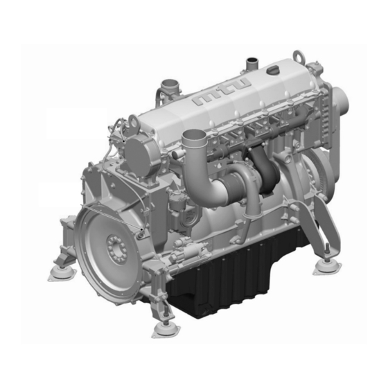
2 General Information 2.1 Engine overview 1 Lifting eye, driving end 5 Engine mounting 9 Flywheel 2 Service indicator 6 Exhaust turbocharger 10 Flywheel housing 3 Cylinder head 7 Oil pan 4 Exhaust elbow 8 Starter MS15022/03E 2014-02 | General Information | 15... - Page 16 1 Lifting eye, free end 5 Crankcase 9 Thermostat housing (re- 2 Air filter 6 Oil pan turn cooler) 3 Air supply 7 Engine governor 10 Belt drive 4 Fuel filter 8 Oil filter Engine model designation Key to the engine model designation 6R 1600 Gxyz Number of cylinders Cylinder arrangement: In-line engine 1600...
-
Page 17: Engine Side And Cylinder Designations
2.2 Engine side and cylinder designations Engine sides are always designated as viewed from the driving end (KS). For cylinder identification (as per DIN ISO 1204), the individual cylinders of the in-line engine are num- bered. The cylinders are numbered starting with No. 1 on driving end. Other components are numbered in the same way, i.e. -
Page 18: Sensors And Actuators
2.3 Sensors and actuators Item Name Monitoring of Camshaft speed Crankshaft speed 18 | General Information | MS15022/03E 2014-02... - Page 19 Item Name Monitoring of Fuel high pressure XY39.A2 Injectors Charge-air pressure XY39.A1 Injectors HP fuel pump (metering unit) Charge-air coolant temperature Lube oil pressure Coolant pressure Coolant temperature MS15022/03E 2014-02 | General Information | 19...
-
Page 20: Technical Data
3 Technical Data 3.1 6R 1600 B30S 60Hz engine data, optimized fuel consumption Explanation: DL Ref. value: Continuous power BL Ref. value: Fuel stop power A Design value G Guaranteed value R Guideline value L Limit value, up to which the engine can be operated, without change (e.g. of power setting) N Not yet defined value - Not applicable X Applicable... - Page 21 COOLANT SYSTEM (HT circuit) Number of cylinders Coolant temperature (at engine connection: outlet to cooling system) °C Coolant temperature after engine, warning °C Coolant temperature after engine, shutdown °C Pressure loss in off-engine cooling system, max. LUBE OIL SYSTEM Number of cylinders Lube oil operating pressure before engine, warning Lube oil operating pressure before engine, shutdown FUEL SYSTEM...
-
Page 22: 1600 B30S 50Hz Engine Data, Optimized Fuel Consumption
3.2 6R 1600 B30S 50Hz engine data, optimized fuel consumption Explanation: DL Ref. value: Continuous power BL Ref. value: Fuel stop power A Design value G Guaranteed value R Guideline value L Limit value, up to which the engine can be operated, without change (e.g. of power setting) N Not yet defined value - Not applicable X Applicable... - Page 23 COOLANT SYSTEM (HT circuit) Number of cylinders Coolant temperature (at engine connection: outlet to cooling system) °C Coolant temperature after engine, warning °C Coolant temperature after engine, shutdown °C Coolant antifreeze content, max. Pressure loss in off-engine cooling system, max. LUBE OIL SYSTEM Number of cylinders Lube oil operating pressure before engine, warning...
-
Page 24: 1600 B40S 50Hz Engine Data, Optimized Emissions
3.3 6R 1600 B40S 50Hz engine data, optimized emissions Explanation: DL Ref. value: Continuous power BL Ref. value: Fuel stop power A Design value G Guaranteed value R Guideline value L Limit value, up to which the engine can be operated, without change (e.g. of power setting) N Not yet defined value - Not applicable X Applicable... - Page 25 Number of cylinders Coolant antifreeze content, max. Pressure loss in off-engine cooling system, max. LUBE OIL SYSTEM Number of cylinders Lube oil operating pressure before engine, warning Lube oil operating pressure before engine, shutdown FUEL SYSTEM Number of cylinders Fuel pressure at engine inlet connection, min. (when engine is starting) -0.5 Fuel pressure at engine inlet connection, max.
-
Page 26: 1600 B40S 50Hz Engine Data, Optimized Fuel Consumption
3.4 6R 1600 B40S 50Hz engine data, optimized fuel consumption Explanation: DL Ref. value: Continuous power BL Ref. value: Fuel stop power A Design value G Guaranteed value R Guideline value L Limit value, up to which the engine can be operated, without change (e.g. of power setting) N Not yet defined value - Not applicable X Applicable... - Page 27 Number of cylinders Coolant antifreeze content, max. Pressure loss in off-engine cooling system, max. LUBE OIL SYSTEM Number of cylinders Lube oil operating pressure before engine, warning Lube oil operating pressure before engine, shutdown FUEL SYSTEM Number of cylinders Fuel pressure at engine inlet connection, min. (when engine is starting) -0.5 Fuel pressure at engine inlet connection, max.
-
Page 28: 1600 B40S 60Hz Engine Data, Optimized Emissions
3.5 6R 1600 B40S 60Hz engine data, optimized emissions Explanation: DL Ref. value: Continuous power BL Ref. value: Fuel stop power A Design value G Guaranteed value R Guideline value L Limit value, up to which the engine can be operated, without change (e.g. of power setting) N Not yet defined value - Not applicable X Applicable... - Page 29 Number of cylinders Coolant antifreeze content, max. Pressure loss in off-engine cooling system, max. LUBE OIL SYSTEM Number of cylinders Lube oil operating pressure before engine, warning Lube oil operating pressure before engine, shutdown FUEL SYSTEM Number of cylinders Fuel pressure at engine inlet connection, min. (when engine is starting) -0.5 Fuel pressure at engine inlet connection, max.
-
Page 30: 1600 B40S 60Hz Engine Data, Optimized Fuel Consumption
3.6 6R 1600 B40S 60Hz engine data, optimized fuel consumption Explanation: DL Ref. value: Continuous power BL Ref. value: Fuel stop power A Design value G Guaranteed value R Guideline value L Limit value, up to which the engine can be operated, without change (e.g. of power setting) N Not yet defined value - Not applicable X Applicable... - Page 31 COOLANT SYSTEM (HT circuit) Number of cylinders Coolant temperature (at engine connection: outlet to cooling system) °C Coolant temperature after engine, warning °C Coolant temperature after engine, shutdown °C Coolant antifreeze content, max. Pressure loss in off-engine cooling system, max. LUBE OIL SYSTEM Number of cylinders Lube oil operating temperature after engine, to...
-
Page 32: 1600 G10F , G20F Engine Data, Optimized Fuel Consumption
3.7 6R 1600 G10F , G20F engine data, optimized fuel consumption Explanation: DL Ref. value: Continuous power BL Ref. value: Fuel stop power A Design value G Guaranteed value R Guideline value L Limit value, up to which the engine can be operated, without change (e.g. of power settings). - Page 33 °C Lube-oil operating pressure before engine, from Lube-oil operating pressure before engine, to Lube-oil operating pressure before engine, warning (speed-de- pendent value, consult MTU) Lube-oil operating pressure before engine, shutdown (speed-de- pendent value, consult MTU) FUEL SYSTEM Number of cylinders Fuel pressure at engine inlet connection, min.
- Page 34 Number of cylinders Oil pan capacity at dipstick mark “min.” (standard oil system) (Op- Liters tion: max. operating inclinations) Oil pan capacity at dipstick mark “max.” (standard oil system) (Op- Liters tion: max. operating inclinations) WEIGHTS / MAIN DIMENSIONS Number of cylinders Engine weight, dry (basic engine configuration acc.
-
Page 35: 1600 G10F , G20F Engine Data, Optimized Exhaust Emissions
3.8 6R 1600 G10F , G20F engine data, optimized exhaust emissions Explanation: DL Ref. value: Continuous power BL Ref. value: Fuel stop power A Design value G Guaranteed value R Guideline value L Limit value, up to which the engine can be operated, without change (e.g. of power settings). - Page 36 °C Lube-oil operating pressure before engine, from Lube-oil operating pressure before engine, to Lube-oil operating pressure before engine, warning (speed-de- pendent value, consult MTU) Lube-oil operating pressure before engine, shutdown (speed-de- pendent value, consult MTU) FUEL SYSTEM Number of cylinders Fuel pressure at engine inlet connection, min.
- Page 37 Number of cylinders Oil pan capacity at dipstick mark “min.” (standard oil system) (Op- Liters tion: max. operating inclinations) Oil pan capacity at dipstick mark “max.” (standard oil system) (Op- Liters tion: max. operating inclinations) WEIGHTS / MAIN DIMENSIONS Number of cylinders Engine weight, dry (basic engine configuration acc.
-
Page 38: 1600 G10S, G20S Engine Data, Epa Stage 3
3.9 6R 1600 G10S, G20S engine data, EPA stage 3 Explanation: DL Ref. value: Continuous power BL Ref. value: Fuel stop power A Design value G Guaranteed value R Guideline value L Limit value, up to which the engine can be operated, without change (e.g. of power settings). N Not yet defined value - Not applicable X Applicable... - Page 39 °C Lube-oil operating pressure before engine, from Lube-oil operating pressure before engine, to Lube-oil operating pressure before engine, warning (speed-de- pendent value, consult MTU) Lube-oil operating pressure before engine, shutdown (speed-de- pendent value, consult MTU) FUEL SYSTEM Number of cylinders Fuel pressure at engine inlet connection, min.
- Page 40 Number of cylinders Oil pan capacity at dipstick mark “min.” (standard oil system) (Op- Liters tion: max. operating inclinations) Oil pan capacity at dipstick mark “max.” (standard oil system) (Op- Liters tion: max. operating inclinations) WEIGHTS / MAIN DIMENSIONS Number of cylinders Engine weight, dry (basic engine configuration acc.
-
Page 41: 1600 G10F, G20F Engine Data, Nonroad Stage Iii A
3.10 6R 1600 G10F, G20F engine data, Nonroad stage III a Explanation: DL Ref. value: Continuous power BL Ref. value: Fuel stop power A Design value G Guaranteed value R Guideline value L Limit value, up to which the engine can be operated, without change (e.g. of power settings). - Page 42 °C Lube-oil operating pressure before engine, from Lube-oil operating pressure before engine, to Lube-oil operating pressure before engine, warning (speed-de- pendent value, consult MTU) Lube-oil operating pressure before engine, shutdown (speed-de- pendent value, consult MTU) FUEL SYSTEM Number of cylinders Fuel pressure at engine inlet connection, min.
- Page 43 Number of cylinders Oil pan capacity at dipstick mark “min.” (standard oil system) (Op- Liters tion: max. operating inclinations) Oil pan capacity at dipstick mark “max.” (standard oil system) (Op- Liters tion: max. operating inclinations) WEIGHTS / MAIN DIMENSIONS Number of cylinders Engine weight, dry (basic engine configuration acc.
-
Page 44: 1600 G40F , G50F Engine Data, Optimized Fuel Consumption
3.11 6R 1600 G40F , G50F engine data, optimized fuel consumption Explanation: DL Ref. value: Continuous power BL Ref. value: Fuel stop power A Design value G Guaranteed value R Guideline value L Limit value, up to which the engine can be operated, without change (e.g. of power settings). N Not yet defined value - Not applicable X Applicable... - Page 45 °C Lube-oil operating pressure before engine, from Lube-oil operating pressure before engine, to Lube-oil operating pressure before engine, warning (speed-de- pendent value, consult MTU) Lube-oil operating pressure before engine, shutdown (speed-de- pendent value, consult MTU) FUEL SYSTEM Number of cylinders Fuel pressure at engine inlet connection, min.
- Page 46 Number of cylinders Oil pan capacity at dipstick mark “min.” (standard oil system) (Op- Liters tion: max. operating inclinations) Oil pan capacity at dipstick mark “max.” (standard oil system) (Op- Liters tion: max. operating inclinations) WEIGHTS / MAIN DIMENSIONS Number of cylinders Engine weight, dry (basic engine configuration acc.
-
Page 47: 1600 G40F , G50F Engine Data, Optimized Exhaust Emissions
3.12 6R 1600 G40F , G50F engine data, optimized exhaust emissions Explanation: DL Ref. value: Continuous power BL Ref. value: Fuel stop power A Design value G Guaranteed value R Guideline value L Limit value, up to which the engine can be operated, without change (e.g. of power settings). N Not yet defined value - Not applicable X Applicable... - Page 48 °C Lube-oil operating pressure before engine, from Lube-oil operating pressure before engine, to Lube-oil operating pressure before engine, warning (speed-de- pendent value, consult MTU) Lube-oil operating pressure before engine, shutdown (speed-de- pendent value, consult MTU) FUEL SYSTEM Number of cylinders Fuel pressure at engine inlet connection, min.
- Page 49 Number of cylinders Oil pan capacity at dipstick mark “min.” (standard oil system) (Op- Liters tion: max. operating inclinations) Oil pan capacity at dipstick mark “max.” (standard oil system) (Op- Liters tion: max. operating inclinations) WEIGHTS / MAIN DIMENSIONS Number of cylinders Engine weight, dry (basic engine configuration acc.
-
Page 50: 1600 G40F, G50F Engine Data, Nonroad Stage Iii A
3.13 6R 1600 G40F, G50F engine data, Nonroad stage III a Explanation: DL Ref. value: Continuous power BL Ref. value: Fuel stop power A Design value G Guaranteed value R Guideline value L Limit value, up to which the engine can be operated, without change (e.g. of power settings). N Not yet defined value - Not applicable X Applicable... - Page 51 °C Lube-oil operating pressure before engine, from Lube-oil operating pressure before engine, to Lube-oil operating pressure before engine, warning (speed-de- pendent value, consult MTU) Lube-oil operating pressure before engine, shutdown (speed-de- pendent value, consult MTU) FUEL SYSTEM Number of cylinders Fuel pressure at engine inlet connection, min.
- Page 52 Number of cylinders Oil pan capacity at dipstick mark “min.” (standard oil system) (Op- Liters tion: max. operating inclinations) Oil pan capacity at dipstick mark “max.” (standard oil system) (Op- Liters tion: max. operating inclinations) WEIGHTS / MAIN DIMENSIONS Number of cylinders Engine weight, dry (basic engine configuration acc.
-
Page 53: 1600 G70F , G80F Engine Data, Optimized Fuel Consumption
3.14 6R 1600 G70F , G80F engine data, optimized fuel consumption Explanation: DL Ref. value: Continuous power BL Ref. value: Fuel stop power A Design value G Guaranteed value R Guideline value L Limit value, up to which the engine can be operated, without change (e.g. of power settings). N Not yet defined value - Not applicable X Applicable... - Page 54 °C Lube-oil operating pressure before engine, from Lube-oil operating pressure before engine, to Lube-oil operating pressure before engine, warning (speed-de- pendent value, consult MTU) Lube-oil operating pressure before engine, shutdown (speed-de- pendent value, consult MTU) FUEL SYSTEM Number of cylinders Fuel pressure at engine inlet connection, min.
- Page 55 Number of cylinders Oil pan capacity at dipstick mark “min.” (standard oil system) (Op- Liters tion: max. operating inclinations) Oil pan capacity at dipstick mark “max.” (standard oil system) (Op- Liters tion: max. operating inclinations) WEIGHTS / MAIN DIMENSIONS Number of cylinders Engine weight, dry (basic engine configuration acc.
-
Page 56: 1600 G70F , G80F Engine Data, Optimized Exhaust Emissions
3.15 6R 1600 G70F , G80F engine data, optimized exhaust emissions Explanation: DL Ref. value: Continuous power BL Ref. value: Fuel stop power A Design value G Guaranteed value R Guideline value L Limit value, up to which the engine can be operated, without change (e.g. of power settings). N Not yet defined value - Not applicable X Applicable... - Page 57 °C Lube-oil operating pressure before engine, from Lube-oil operating pressure before engine, to Lube-oil operating pressure before engine, warning (speed-de- pendent value, consult MTU) Lube-oil operating pressure before engine, shutdown (speed-de- pendent value, consult MTU) FUEL SYSTEM Number of cylinders Fuel pressure at engine inlet connection, min.
- Page 58 Number of cylinders Oil pan capacity at dipstick mark “min.” (standard oil system) (Op- Liters tion: max. operating inclinations) Oil pan capacity at dipstick mark “max.” (standard oil system) (Op- Liters tion: max. operating inclinations) WEIGHTS / MAIN DIMENSIONS Number of cylinders Engine weight, dry (basic engine configuration acc.
-
Page 59: 1600 G70S, G80S Engine Data, Epa Stage 3
3.16 6R 1600 G70S, G80S engine data, EPA stage 3 Explanation: DL Ref. value: Continuous power BL Ref. value: Fuel stop power A Design value G Guaranteed value R Guideline value L Limit value, up to which the engine can be operated, without change (e.g. of power settings). N Not yet defined value - Not applicable X Applicable... - Page 60 °C Lube-oil operating pressure before engine, from Lube-oil operating pressure before engine, to Lube-oil operating pressure before engine, warning (speed-de- pendent value, consult MTU) Lube-oil operating pressure before engine, shutdown (speed-de- pendent value, consult MTU) FUEL SYSTEM Number of cylinders Fuel pressure at engine inlet connection, min.
- Page 61 Number of cylinders Oil pan capacity at dipstick mark “min.” (standard oil system) (Op- Liters tion: max. operating inclinations) Oil pan capacity at dipstick mark “max.” (standard oil system) (Op- Liters tion: max. operating inclinations) WEIGHTS / MAIN DIMENSIONS Number of cylinders Engine weight, dry (basic engine configuration acc.
-
Page 62: 1600 G70F, G80F Engine Data, Nonroad Stage Iii A
3.17 6R 1600 G70F, G80F engine data, Nonroad stage III a Explanation: DL Ref. value: Continuous power BL Ref. value: Fuel stop power A Design value G Guaranteed value R Guideline value L Limit value, up to which the engine can be operated, without change (e.g. of power settings). N Not yet defined value - Not applicable X Applicable... - Page 63 °C Lube-oil operating pressure before engine, from Lube-oil operating pressure before engine, to Lube-oil operating pressure before engine, warning (speed-de- pendent value, consult MTU) Lube-oil operating pressure before engine, shutdown (speed-de- pendent value, consult MTU) FUEL SYSTEM Number of cylinders Fuel pressure at engine inlet connection, min.
- Page 64 Number of cylinders Oil pan capacity at dipstick mark “min.” (standard oil system) (Op- Liters tion: max. operating inclinations) Oil pan capacity at dipstick mark “max.” (standard oil system) (Op- Liters tion: max. operating inclinations) WEIGHTS / MAIN DIMENSIONS Number of cylinders Engine weight, dry (basic engine configuration acc.
-
Page 65: Firing Order
3.18 Firing order Firing order Number of cylinders Firing order 2–4–1–5–3–6 MS15022/03E 2014-02 | Technical Data | 65... -
Page 66: Engine - Main Dimensions
3.19 Engine – Main dimensions Engine – Main dimensions Length (A) approx. 1630 mm Width (B) approx. 920 mm Height (C) approx. 1185 mm 66 | Technical Data | MS15022/03E 2014-02... -
Page 67: Operation
4 Operation 4.1 Putting the engine into operation after extended out-of-service periods (>3 months) Preconditions ☑Engine is stopped and starting disabled. ☑MTU Preservation and Represervation Specifications (A001070/..) are available. Putting the PowerPack into operation after extended out-of-service-periods (>3 months) Item Action Engine Depreserve (→... -
Page 68: Putting The Engine Into Operation After Scheduled Out-Of-Service-Period
4.2 Putting the engine into operation after scheduled out-of- service-period Preconditions ☑Engine is stopped and starting disabled. Startup Item Task Lube oil system Check engine oil level (→ Page 92). Coolant system Check engine coolant level (→ Page 95). Monitoring equipment Carry out lamp test (see manufacturer's documentation). -
Page 69: Engine Start In Manual Operation (Trials)
4.3 Engine start in manual operation (trials) Preconditions ☑Generator is not connected to network. ☑External start interlock is not active. DANGER Rotating and moving engine parts. Risk of crushing, danger of parts of the body being caught or pulled in! •... -
Page 70: Safety System - Override
4.4 Safety system – Override NOTICE Safety functions and engine shutdown alarms will be disregarded. Severe material damage! • Initiate emergency start only in emergency situations. NOTICE Inadmissible operating status. Severe damage to property! • Use override function only in hazardous situations to ensure full capability in the event of engine faults. -
Page 71: Operational Checks
4.5 Operational checks DANGER Rotating and moving engine parts. Risk of crushing, danger of parts of the body being caught or pulled in! • Only run the engine at low power. Keep away from the engine's danger zone. WARNING High level of engine noise when the engine is running. Risk of damage to hearing! •... -
Page 72: Engine Stop In Manual Operation (Trials)
4.6 Engine stop in manual operation (trials) Preconditions ☑Generator is not connected to network. ☑Engine is running in manual mode. Preparation Item Task Engine After the generator breaker has been opened, allow the engine to cool down by running it idle for approx. 5 minutes. Stop engine Item Task... -
Page 73: Emergency Stop
4.7 Emergency stop NOTICE An emergency stop causes extreme stress to the engine plant. Risk of overheating, damage to components! • Initiate emergency stop only in emergency situations. Emergency stop Item Action Emergency stop pushbutton Press pushbutton. • Engine is stopped by disconnecting the power supply to the ECU; •... -
Page 74: After Stopping The Engine - Engine Remains Ready For Operation
4.8 After stopping the engine – Engine remains ready for operation After stopping the engine Item Action Engine/generator/pump Select operating mode, e.g. MANUAL, AUTOMATIC OPERATION. control 74 | Operation | MS15022/03E 2014-02... -
Page 75: After Stopping The Engine - Putting The Engine Out Of Operation
4.9 After stopping the engine – Putting the engine out of operation Preconditions ☑MTU Fluids and Lubricants Specifications (A001063/..) are available. After stopping the engine Item Task Coolant circuit Drain engine coolant (→ Page 97) if: • the engine room is not heated;... -
Page 76: Maintenance
The specification of fluids and lubricants, guidelines for maintenance and change intervals as well as a list of approved fluids and lubricants are provided in the MTU Fluids and Lubricants Specifications A001063/.. Use only fluids and lubricants which comply with the MTU Fluids and Lubricants Specifica- tions. -
Page 77: Maintenance Task Reference Table
5.2 Maintenance task reference table The maintenance tasks and intervals for this product are defined in the Maintenance Booklet. The Main- tenance Booklet is a stand-alone publication. The task numbers in this table provide reference to the maintenance tasks specified in the Maintenance Booklet. -
Page 78: Troubleshooting
6 Troubleshooting 6.1 Troubleshooting Engine does not turn when starter is actuated Component Probable Cause Task Battery Low or defective Charge or replace (see manufacturer's documentation). Cable connections defective Check whether cable connections are properly secured (see manufacturer's documentation). Starter Engine wiring or starter defective Check whether cable connections are properly secured, contact Service. - Page 79 Component Probable Cause Task Engine wiring Defective Check (→ Page 105). Engine Overload Contact Service. Engine speed not steady Component Probable Cause Task Fuel injection equip- Injector defective Contact Service. ment Speed sensor Defective Contact Service. Fuel system Not vented Vent fuel system (→...
-
Page 80: Task Description
7 Task Description 7.1 Engine 7.1.1 Engine – Barring with starting system Preconditions ☑External pushbutton “Bar engine without starting” is provided. DANGER Rotating and moving engine parts. Risk of crushing, danger of parts of the body being caught or pulled in! •... -
Page 81: Engine - Test Run
7.1.2 Engine – Test run DANGER Rotating and moving engine parts. Risk of crushing, danger of parts of the body being caught or pulled in! • Before cranking the engine with starter system, make sure that there are no persons in the en- gine's danger zone. -
Page 82: Valve Drive
7.2 Valve Drive 7.2.1 Valve clearance – Check and adjustment Preconditions ☑Engine is stopped and starting disabled. ☑Engine coolant temperature is max. 40 °C. ☑Valves are closed. Special tools, Material, Spare parts Designation / Use Part No. Qty. Feeler gage Y20098771 Torque wrench, 20-100 Nm F30026582... -
Page 83: Adjusting Valve Clearance
Adjusting valve clearance Loosen locknut (1) and unscrew adjusting screw (2) by a few threads. Insert feeler gauge between valve bridge and rocker arm (3). Readjust adjusting screw (2) so that the feeler gauge just passes through the gap. Tighten locknut (1) with torque wrench to specified torque, holding adjusting screw (2) firm with Allen screw. -
Page 84: Cylinder Head Cover - Removal And Installation
7.2.2 Cylinder head cover – Removal and installation Preconditions ☑Engine is stopped and starting disabled. Cylinder head cover – Removal and installation Loosen and remove screws. Remove cylinder head cover. Clean installation surface. Check condition of profile gasket and re- place if required. -
Page 85: Fuel System
7.3 Fuel System 7.3.1 Fuel system – Venting Preconditions ☑Engine is stopped and starting disabled. WARNING Fuels are combustible. Risk of fire and explosion! • Avoid open flames, electrical sparks and ignition sources. • Do not smoke. Fuel system – Venting Unlock fuel priming pump, screw out han- dle (1). -
Page 86: Fuel Filter
7.4 Fuel Filter 7.4.1 Fuel filter – Replacement Preconditions ☑Engine is stopped and starting disabled. Special tools, Material, Spare parts Designation / Use Part No. Qty. Filter wrench F30379104 Engine oil Easy-change filter (→ Spare Parts Catalog) WARNING Fuels are combustible. Risk of fire and explosion! •... -
Page 87: Fuel Prefilter - Replacement
7.4.2 Fuel prefilter – Replacement Preconditions ☑Engine is stopped and starting disabled. ☑System is not under pressure. Special tools, Material, Spare parts Designation / Use Part No. Qty. Filter wrench F30379104 Engine oil Easy-change filter (→ Spare Parts Catalog) WARNING Fuels are combustible. -
Page 88: Air Filter
7.5 Air Filter 7.5.1 Air filter ‒ Replacement Special tools, Material, Spare parts Designation / Use Part No. Qty. Air filter (→ Spare Parts Catalog) Air filter ‒ Replacement Remove air filter and install new one (→ Page 89). Reset signal ring of service indicator (→ Page 90). 88 | Task Description | MS15022/03E 2014-02... -
Page 89: Air Filter - Removal And Installation
7.5.2 Air filter – Removal and installation Preconditions ☑Engine is stopped and starting disabled. Air filter – Removal and installa- tion Loosen clamp (2). Remove air filter (1) and clamp (2) from connecting flange of intake housing (3). Verify that there are no objects in the flange of the intake housing (3) and clean Place new air filter (1) with clamp (2) onto intake housing (3). -
Page 90: Air Intake
7.6 Air Intake 7.6.1 Service indicator – Signal ring position check Preconditions ☑Engine is stopped and starting disabled. Checking signal ring position Replace air filter, if the signal ring (2) is completely visible in the red area of the service indicator control window (3) (→... -
Page 91: Starting Equipment
7.7 Starting Equipment 7.7.1 Starter – Condition check Preconditions ☑Engine is stopped and starting disabled. Checking starter condition Check securing screws of starter for secure seating and tighten if required. Check wiring (→ Page 105). MS15022/03E 2014-02 | Task Description | 91... -
Page 92: Lube Oil System, Lube Oil Circuit
7.8 Lube Oil System, Lube Oil Circuit 7.8.1 Engine oil level – Check Preconditions ☑Engine is stopped and starting disabled. Oil level check prior to engine start Remove oil dipstick (1) from guide tube and wipe it. Insert oil dipstick (1) into guide tube up to the stop, withdraw after approx. -
Page 93: Engine Oil – Change
7.8.2 Engine oil – Change Preconditions ☑Engine is stopped and starting disabled. ☑Engine is at operating temperature. ☑MTU Fluids and Lubricants Specifications (A001063/..) are available. Special tools, Material, Spare parts Designation / Use Part No. Qty. Engine oil WARNING Hot oil. -
Page 94: Oil Filtration / Cooling
7.9 Oil Filtration / Cooling 7.9.1 Engine oil filter – Replacement Preconditions ☑Engine is stopped and starting disabled. Special tools, Material, Spare parts Designation / Use Part No. Qty. Torque wrench, 8-40 Nm F30043446 Ratchet adapter F30027340 Socket, 32 mm F30006120 Engine oil Oil filter element... -
Page 95: Circuit
7.10 Coolant Circuit, General, High-Temperature Circuit 7.10.1 Engine coolant – Level check Preconditions ☑Engine is stopped and starting disabled. ☑MTU Fluids and Lubricants Specifications (A001063/..) are available. WARNING Coolant is hot and under pressure. Risk of injury and scalding! • Let the engine cool down. -
Page 96: Engine Coolant – Change
7.10.2 Engine coolant – Change Special tools, Material, Spare parts Designation / Use Part No. Qty. Coolant Engine coolant change Drain engine coolant (→ Page 97). Fill with engine coolant (→ Page 98). 96 | Task Description | MS15022/03E 2014-02... -
Page 97: Engine Coolant – Draining
7.10.3 Engine coolant – Draining Preconditions ☑Engine is stopped and starting disabled. Special tools, Material, Spare parts Designation / Use Part No. Qty. Engine oil Sealing ring (→ Spare Parts Catalog) WARNING Coolant is hot and under pressure. Risk of injury and scalding! •... -
Page 98: Engine Coolant – Filling
7.10.4 Engine coolant – Filling Preconditions ☑Engine is stopped and starting disabled. ☑MTU Fluids and Lubricants Specifications (A001063/..) are available. Special tools, Material, Spare parts Designation / Use Part No. Qty. Coolant WARNING Coolant is hot and under pressure. Risk of injury and scalding! •... - Page 99 Final steps Start the engine and operate it at idle speed for some minutes. Check coolant level (→ Page 95), top up with coolant if required. MS15022/03E 2014-02 | Task Description | 99...
-
Page 100: Engine Coolant Pump – Relief Bore Check
7.10.5 Engine coolant pump – Relief bore check DANGER Rotating and moving engine parts. Risk of crushing, danger of parts of the body being caught or pulled in! • Only run the engine at low power. Keep away from the engine's danger zone. WARNING High level of engine noise when the engine is running. -
Page 101: Belt Drive
7.11 Belt Drive 7.11.1 Drive belt – Adjustment Preconditions ☑Engine is stopped and starting disabled. Fan drive – Adjusting belt ten- sion Loosen screws (1). Screw in nut (2) to set the required belt tension. Tighten screws (1). Check drive belt tension for compliance with specifications (→... -
Page 102: Drive Belt – Condition Check
7.11.2 Drive belt – Condition check Preconditions ☑Engine is stopped and starting disabled. Checking condition Item Findings Action Drive belt A Singular cracks None Drive belt B Cracks on entire circumference Fit new part (→ Page 104) Drive belt C Chunking Drive belt Fouling by oil, overheating... -
Page 103: Drive Belt – Tension Check
7.11.3 Drive belt – Tension check Preconditions ☑Engine is stopped and starting disabled. Special tools, Material, Spare parts Designation / Use Part No. Qty. Tester Y4345711 Belt tension tester, 500-1400 N Y20097430 Belt tension tester, 1300-3100 N Y20097431 Fan drive – Checking belt ten- sion Remove protective cover. -
Page 104: Drive Belt – Replacement
7.11.4 Drive belt – Replacement Preconditions ☑Engine is stopped and starting disabled. Special tools, Material, Spare parts Designation / Use Part No. Qty. Drive belt (→ Spare Parts Catalog) Replacing fan drive belt Remove protective cover from radiator. Remove fan. Loosen securing screws (3). -
Page 105: Wiring (General) For Engine/Gearbox/Unit
7.12 Wiring (General) for Engine/Gearbox/Unit 7.12.1 Engine wiring – Check Preconditions ☑Engine is stopped and starting disabled. Special tools, Material, Spare parts Designation / Use Part No. Qty. Isopropyl alcohol X00058037 Checking engine wiring Check securing screws of cable clamps on engine and tighten loose threaded connections. Ensure that cables are fixed in their clamps and cannot swing freely. -
Page 106: Accessories For (Electronic) Engine Governor / Control System
7.13 Accessories for (Electronic) Engine Governor / Control System 7.13.1 Engine governor and connectors – Cleaning Preconditions ☑Engine is stopped and starting disabled. Special tools, Material, Spare parts Designation / Use Part No. Qty. Isopropyl alcohol X00058037 Note: Always use test connectors to enter the connectors. Never use test leads for this purpose. Otherwise the contacts could be bent. -
Page 107: Engine Governor – Checking Plug Connections
7.13.2 Engine governor – Checking plug connections Preconditions ☑Engine is stopped and starting disabled. Checking engine governor plug connections Check firm seating of all connectors on the engine governor. Ensure that the clips (1) are engaged. Check firm seating of all screws (2) on en- gine governor cable clamps. -
Page 108: Abbreviations
Association of American standardization organiza- tions Exhaust turbocharger/exhaust turbocharg- Air Temperature Sensor Baureihe (Series) Betriebsstoffvorschrift (Fluids and Lubri- MTU Publication No. A01061/.. cants Specifications) Controller Area Network Data bus system, bus standard Calibration Drift Compensation Drift correction setting with DiaSys in engine gover-... - Page 109 Abbre- Meaning Explanation viation Engine Data Module Memory module for engine data Electrically Erasable Programmable Read PROM Only Memory EFPA Electronic Foot Pedal Assembly Electronic accelerator pedal Exhaust Gas Recirculation Engine Ident Label Engine Monitoring Unit Engine monitoring unit ESCM Extreme Site Condition Management Power reduction with extreme site conditions Spare Parts Catalog...
- Page 110 Abbre- Meaning Explanation viation Original Equipment Manufacturer Optimized Idle Oil Level Sensor Monitors oil level Oil pressure sensor Monitors oil pressure Oil Temperature Sensor Monitors oil temperature Top Dead Center Panel Control panel Peripheral Interface Module Pulse Width Modulation Modulated signal P-xyz Pressure-xyz Pressure measuring point xyz...
-
Page 111: Mtu Contact Persons/Service Partners
Local support Experienced and qualified specialists place their knowledge and expertise at your disposal. For locally available support, go to the MTU Internet site: http://www.mtu-online.com 24h hotline With our 24h hotline and the outstanding flexibility of our service staff, we are always ready to assist you –... -
Page 112: Special Tools
9 Appendix B 9.1 Special Tools Angular screw driver, set 2-10 mm Part No.: F30453050 Qty.: Used in: 7.2.1 Valve clearance – Check and adjustment (→ Page 82) Belt tension tester, 1300-3100 N Part No.: Y20097431 Qty.: Used in: 7.11.3 Drive belt – Tension check (→ Page 103) Belt tension tester, 500-1400 N Part No.: Y20097430... - Page 113 Box wrench, 14 mm Part No.: F30028346 Qty.: Used in: 7.2.1 Valve clearance – Check and adjustment (→ Page 82) Feeler gage Part No.: Y20098771 Qty.: Used in: 7.2.1 Valve clearance – Check and adjustment (→ Page 82) Filter wrench Part No.: F30379104 Qty.:...
- Page 114 Socket, 32 mm Part No.: F30006120 Qty.: Used in: 7.9.1 Engine oil filter – Replacement (→ Page 94) Tester Part No.: Y4345711 Qty.: Used in: 7.11.3 Drive belt – Tension check (→ Page 103) Torque wrench, 20-100 Nm Part No.: F30026582 Qty.: Used in:...
-
Page 115: Index
100 6R 1600 G10F , G20F engine data, optimized exhaust Engine governor emissions 35 – Checking plug connections 107 6R 1600 G10F , G20F engine data, optimized fuel con- – Cleaning 106 sumption 32 Engine layout 15 6R 1600 G10F, G20F engine data, Nonroad stage III a 41... - Page 116 Safety regulations – Consumables 12 – Environmental protection 12 – Fire prevention 12 – Fluids and lubricants 12 – Important provisions 5 – Maintenance work 9 – Operation 8 – Organizational requirements 6 – Personnel requirements 6 – Repair work 9 –...
Need help?
Do you have a question about the 6R 1600 G10F and is the answer not in the manual?
Questions and answers