
Related Manuals for MTU 6R 1600 G10F


Summary of Contents for MTU 6R 1600 G10F
-
Page 1: Operating Instructions
Operating Instructions Diesel engine 6R 1600 G10F, G20F 6R 1600 G40F, G50F 6R 1600 G70F, G80F 6R 1600 G10S, G20S 6R 1600 G70S, G80S 6R 1600 B30S, B40S MS15022/02E... - Page 2 This Publication is protected by copyright and may not be used in any way whether in whole or in part without the prior written permission of MTU Friedrichshafen GmbH. This restriction also applies to copyright, distribution, translation, micro‐ filming and storage or processing on electronic systems including data bases and online services.
-
Page 3: Table Of Contents
5.2 Maintenance task reference table 3.6 6R 1600 B40S 60Hz engine data, optimized fuel consumption 3.7 6R 1600 G10F , G20F engine data, 6 Troubleshooting optimized fuel consumption 3.8 6R 1600 G10F , G20F engine data, 6.1 Troubleshooting optimized exhaust emissions 3.9 6R 1600 G10S, G20S engine data, EPA... - Page 4 7.8.1 Engine oil level – Check 8 Appendix A 7.8.2 Engine oil – Change 8.1 Abbreviations 7.9 Oil Filtration / Cooling 8.2 MTU contacts/service partners 7.9.1 Engine oil filter – Replacement 7.10 Coolant Circuit, General, High- Temperature Circuit 9 Appendix B 7.10.1 Engine coolant –...
-
Page 5: Safety
Correct use also includes observation of and compliance with the maintenance specifications. Modifications or conversions Unauthorized modifications to the engine represent a safety risk. MTU will accept no liability or warranty claims for any damage caused by unauthorized modifications or conversions. Spare parts Only genuine MTU spare parts must be used to replace components or assemblies. -
Page 6: Personnel And Organizational Requirements
1.2 Personnel and organizational requirements Personnel requirements All work on the engine shall be carried out by trained and qualified personnel only. The specified legal minimum age must be observed. The operator must specify the responsibilities of the operating, maintenance and repair personnel. Organizational measures This publication must be issued to all personnel involved in operation, maintenance, repair or transporta‐... -
Page 7: Transport
Place the engine only on an even, firm surface. Ensure appropriate consistency and load-bearing capacity of the ground or support surface. Never place an engine on the oil pan, unless expressively authorized by MTU on a case-to-case basis to do so. -
Page 8: Safety Regulations For Startup And Operation
Safety requirements for initial operation Prior to initial operation of the unit, install the assembly or unit according to the specifications and check the installation according to the MTU specifications. Before putting the device or plant into operation, always ensure: •... -
Page 9: Safety Regulations For Maintenance And Repair Work
1.5 Safety regulations for maintenance and repair work Safety regulations for maintenance and repair work Have maintenance and repair work carried out by qualified and authorized personnel only. Allow the engine to cool down before starting maintenance work (risk of explosion of oil vapors). Before starting work, relieve pressure in systems and compressed-air lines which are to be opened. - Page 10 Do not use the assembly or system as ground terminal. Do not route the welding lead over or near the wiring harnesses of MTU systems. The welding current may otherwise induce an interference voltage in the wiring harnesses which could conceivably damage the electrical system.
- Page 11 For conducting light-beam procedures and measurement work, only the following laser devices must be used: • Laser devices of classes 1, 2 or 3A. • Laser devices of class 3B, which have maximum output in the visible wavelength range (400 to 700 nm), a maximum output of 5 mW, and in which the beam axis and surface are designed to prevent any risk to the eyes.
-
Page 12: Auxiliary Materials, Fluids And Lubricants, Fire Prevention And Environmental Protection
Use only fuel of prescribed quality to comply with emission limit values. Dispose of used fluids, lubricants and filters in accordance with local regulations. Within the EU, batteries can be returned free of charge to MTU FN / MTU Onsite Energy where they are subjected to proper recycling procedures. - Page 13 Lead • When working with lead or lead-containing compounds, avoid direct contact to the skin and do not inhale lead vapors. • Adopt suitable measures to avoid the formation of lead dust. • Switch on extraction system. • Wash hands after contact with lead or lead-containing substances. Compressed air Observe special safety precautions when working with compressed air: •...
-
Page 14: Conventions For Safety Instructions In The Text
1.7 Conventions for safety instructions in the text DANGER In the event of immediate danger. Consequences: Death or serious injury • Remedial action WARNING In the event of potentially dangerous situations. Consequences: Death or serious injury • Remedial action CAUTION In the event of dangerous situations. -
Page 15: General Information
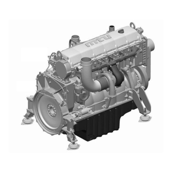
2 General Information 2.1 Engine layout 1 Lifting eye, driving end 5 Engine mounting 9 Flywheel 2 Service indicator 6 Exhaust turbocharger 10 Flywheel housing 3 Cylinder head 7 Oil pan 4 Exhaust elbow 8 Starter MS15022/02E 2012-04 | General Information | 15... - Page 16 1 Lifting eye, free end 5 Crankcase 9 Thermostat housing (re‐ 2 Air filter 6 Oil pan turn cooler) 3 Air supply 7 Engine governor 10 Belt drive 4 Fuel filter 8 Oil filter Engine model designation Key to the engine model designation 6R 1600 Gxyz Number of cylinders Cylinder arrangement: In-line engine 1600...
-
Page 17: Engine Side And Cylinder Designations
2.2 Engine side and cylinder designations Engine sides are always designated as viewed from the driving end (KS). For cylinder identification (as per DIN ISO 1204), the individual cylinders of the in-line engine are num‐ bered. The cylinders are numbered starting with No. 1 on driving end. Other components are numbered in the same way, i.e. -
Page 18: Sensors And Actuators
2.3 Sensors and actuators Item Designation Monitoring of Camshaft speed Crankshaft speed 18 | General Information | MS15022/02E 2012-04... - Page 19 Item Designation Monitoring of High-pressure fuel XY39.A2 Injectors Charge-air pressure XY39.A1 Injectors Fuel pump HDP (time measurement unit) Charge-air temperature Lube oil pressure Coolant pressure Coolant temperature MS15022/02E 2012-04 | General Information | 19...
-
Page 20: Technical Data
3 Technical Data 3.1 6R 1600 B30S 60Hz engine data, optimized fuel consumption Explanation: DL Ref. value: Continuous power BL Ref. value: Fuel stop power A Design value G Guaranteed value R Guideline value L Limit value, up to which the engine can be operated, without change (e.g. of power setting) N Not yet defined value - Not applicable X Applicable... - Page 21 COMBUSTION AIR / EXHAUST GAS Number of cylinders Charge-air pressure before cylinder - DL bar abs COOLANT SYSTEM (HT circuit) Number of cylinders Coolant temperature (at engine connection: outlet to cooling system) °C Coolant temperature after engine, warning °C Coolant temperature after engine, shutdown °C Pressure loss in off-engine cooling system, max.
- Page 22 ACOUSTICS Number of cylinders Exhaust noise, unsilenced - DL (sound power level LW, ISO 6798, +3dB(A) dB(A) tolerance) Engine surface noise with attenuated intake noise (filter) - DL (sound power dB(A) level LW, ISO 6798+2dB(A) tolerance) 22 | Technical Data | MS15022/02E 2012-04...
-
Page 23: 1600 B30S 50Hz Engine Data, Optimized Fuel Consumption
3.2 6R 1600 B30S 50Hz engine data, optimized fuel consumption Explanation: DL Ref. value: Continuous power BL Ref. value: Fuel stop power A Design value G Guaranteed value R Guideline value L Limit value, up to which the engine can be operated, without change (e.g. of power setting) N Not yet defined value - Not applicable X Applicable... - Page 24 COOLANT SYSTEM (HT circuit) Number of cylinders Coolant temperature (at engine connection: outlet to cooling system) °C Coolant temperature after engine, warning °C Coolant temperature after engine, shutdown °C Coolant antifreeze content, max. Pressure loss in off-engine cooling system, max. LUBE OIL SYSTEM Number of cylinders Lube oil operating pressure before engine, warning...
-
Page 25: 1600 B40S 50Hz Engine Data, Optimized Emissions
3.3 6R 1600 B40S 50Hz engine data, optimized emissions Explanation: DL Ref. value: Continuous power BL Ref. value: Fuel stop power A Design value G Guaranteed value R Guideline value L Limit value, up to which the engine can be operated, without change (e.g. of power setting) N Not yet defined value - Not applicable X Applicable... - Page 26 Number of cylinders Coolant antifreeze content, max. Pressure loss in off-engine cooling system, max. LUBE OIL SYSTEM Number of cylinders Lube oil operating pressure before engine, warning Lube oil operating pressure before engine, shutdown FUEL SYSTEM Number of cylinders Fuel pressure at engine inlet connection, min. (when engine is starting) -0.5 Fuel pressure at engine inlet connection, max.
-
Page 27: 1600 B40S 50Hz Engine Data, Optimized Fuel Consumption
3.4 6R 1600 B40S 50Hz engine data, optimized fuel consumption Explanation: DL Ref. value: Continuous power BL Ref. value: Fuel stop power A Design value G Guaranteed value R Guideline value L Limit value, up to which the engine can be operated, without change (e.g. of power setting) N Not yet defined value - Not applicable X Applicable... - Page 28 Number of cylinders Coolant temperature after engine, shutdown °C Coolant antifreeze content, max. Pressure loss in off-engine cooling system, max. LUBE OIL SYSTEM Number of cylinders Lube oil operating pressure before engine, warning Lube oil operating pressure before engine, shutdown FUEL SYSTEM Number of cylinders Fuel pressure at engine inlet connection, min.
-
Page 29: 1600 B40S 60Hz Engine Data, Optimized Emissions
3.5 6R 1600 B40S 60Hz engine data, optimized emissions Explanation: DL Ref. value: Continuous power BL Ref. value: Fuel stop power A Design value G Guaranteed value R Guideline value L Limit value, up to which the engine can be operated, without change (e.g. of power setting) N Not yet defined value - Not applicable X Applicable... - Page 30 Number of cylinders Coolant antifreeze content, max. Pressure loss in off-engine cooling system, max. LUBE OIL SYSTEM Number of cylinders Lube oil operating pressure before engine, warning Lube oil operating pressure before engine, shutdown FUEL SYSTEM Number of cylinders Fuel pressure at engine inlet connection, min. (when engine is starting) -0.5 Fuel pressure at engine inlet connection, max.
-
Page 31: 1600 B40S 60Hz Engine Data, Optimized Fuel Consumption
3.6 6R 1600 B40S 60Hz engine data, optimized fuel consumption Explanation: DL Ref. value: Continuous power BL Ref. value: Fuel stop power A Design value G Guaranteed value R Guideline value L Limit value, up to which the engine can be operated, without change (e.g. of power setting) N Not yet defined value - Not applicable X Applicable... - Page 32 COOLANT SYSTEM (HT circuit) Number of cylinders Coolant temperature (at engine connection: outlet to cooling system) °C Coolant temperature after engine, warning °C Coolant temperature after engine, shutdown °C Coolant antifreeze content, max. Pressure loss in off-engine cooling system, max. LUBE OIL SYSTEM Number of cylinders Lube oil operating temperature after engine, to...
-
Page 33: 1600 G10F , G20F Engine Data, Optimized Fuel Consumption
3.7 6R 1600 G10F , G20F engine data, optimized fuel consumption Explanation: DL Ref. value: Continuous power BL Ref. value: Fuel stop power A Design value G Guaranteed value R Guideline value L Limit value, up to which the engine can be operated, without change (e.g. of power settings). - Page 34 °C Lube-oil operating pressure before engine, from Lube-oil operating pressure before engine, to Lube-oil operating pressure before engine, warning (speed-de‐ pendent value, consult MTU) Lube-oil operating pressure before engine, shutdown (speed- dependent value, consult MTU) FUEL SYSTEM Number of cylinders Fuel pressure at engine inlet connection, min.
- Page 35 CAPACITIES Number of cylinders Engine coolant capacity, engine side (without cooling equip‐ Liters ment) Total engine oil capacity for initial filling (standard oil system) Liters Oil change capacity, max. (standard oil system) Liters Oil change quantity, max. (standard oil system) (Option: max. Liters operating inclinations) Oil pan capacity at dipstick mark “min.”...
-
Page 36: 1600 G10F , G20F Engine Data, Optimized Exhaust Emissions
3.8 6R 1600 G10F , G20F engine data, optimized exhaust emissions Explanation: DL Ref. value: Continuous power BL Ref. value: Fuel stop power A Design value G Guaranteed value R Guideline value L Limit value, up to which the engine can be operated, without change (e.g. of power settings). - Page 37 °C Lube-oil operating pressure before engine, from Lube-oil operating pressure before engine, to Lube-oil operating pressure before engine, warning (speed-de‐ pendent value, consult MTU) Lube-oil operating pressure before engine, shutdown (speed- dependent value, consult MTU) FUEL SYSTEM Number of cylinders Fuel pressure at engine inlet connection, min.
- Page 38 CAPACITIES Number of cylinders Engine coolant capacity, engine side (without cooling equip‐ Liters ment) Total engine oil capacity for initial filling (standard oil system) Liters Oil change capacity, max. (standard oil system) Liters Oil change quantity, max. (standard oil system) (Option: max. Liters operating inclinations) Oil pan capacity at dipstick mark “min.”...
-
Page 39: R 1600 G10S, G20S Engine Data, Epa Stage 3
3.9 6R 1600 G10S, G20S engine data, EPA stage 3 Explanation: DL Ref. value: Continuous power BL Ref. value: Fuel stop power A Design value G Guaranteed value R Guideline value L Limit value, up to which the engine can be operated, without change (e.g. of power settings). N Not yet defined value - Not applicable X Applicable... - Page 40 °C Lube-oil operating pressure before engine, from Lube-oil operating pressure before engine, to Lube-oil operating pressure before engine, warning (speed-de‐ pendent value, consult MTU) Lube-oil operating pressure before engine, shutdown (speed- dependent value, consult MTU) FUEL SYSTEM Number of cylinders Fuel pressure at engine inlet connection, min.
- Page 41 Number of cylinders Oil pan capacity at dipstick mark “min.” (standard oil system) Liters (Option: max. operating inclinations) Oil pan capacity at dipstick mark “max.” (standard oil system) Liters (Option: max. operating inclinations) WEIGHTS / MAIN DIMENSIONS Number of cylinders Engine weight, dry (basic engine configuration acc.
-
Page 42: 1600 G10F, G20F Engine Data, Nonroad Stage Iii A
3.10 6R 1600 G10F, G20F engine data, Nonroad stage III a Explanation: DL Ref. value: Continuous power BL Ref. value: Fuel stop power A Design value G Guaranteed value R Guideline value L Limit value, up to which the engine can be operated, without change (e.g. of power settings). - Page 43 °C Lube-oil operating pressure before engine, from Lube-oil operating pressure before engine, to Lube-oil operating pressure before engine, warning (speed-de‐ pendent value, consult MTU) Lube-oil operating pressure before engine, shutdown (speed- dependent value, consult MTU) FUEL SYSTEM Number of cylinders Fuel pressure at engine inlet connection, min.
- Page 44 Number of cylinders Oil pan capacity at dipstick mark “min.” (standard oil system) Liters (Option: max. operating inclinations) Oil pan capacity at dipstick mark “max.” (standard oil system) Liters (Option: max. operating inclinations) WEIGHTS / MAIN DIMENSIONS Number of cylinders Engine weight, dry (basic engine configuration acc.
-
Page 45: 1600 G40F , G50F Engine Data, Optimized Fuel Consumption
3.11 6R 1600 G40F , G50F engine data, optimized fuel consumption Explanation: DL Ref. value: Continuous power BL Ref. value: Fuel stop power A Design value G Guaranteed value R Guideline value L Limit value, up to which the engine can be operated, without change (e.g. of power settings). N Not yet defined value - Not applicable X Applicable... - Page 46 °C Lube-oil operating pressure before engine, from Lube-oil operating pressure before engine, to Lube-oil operating pressure before engine, warning (speed-de‐ pendent value, consult MTU) Lube-oil operating pressure before engine, shutdown (speed- dependent value, consult MTU) FUEL SYSTEM Number of cylinders Fuel pressure at engine inlet connection, min.
- Page 47 CAPACITIES Number of cylinders Engine coolant capacity, engine side (without cooling equip‐ Liters ment) Total engine oil capacity for initial filling (standard oil system) Liters Oil change capacity, max. (standard oil system) Liters Oil change quantity, max. (standard oil system) (Option: max. Liters operating inclinations) Oil pan capacity at dipstick mark “min.”...
-
Page 48: 1600 G40F , G50F Engine Data, Optimized Exhaust Emissions
3.12 6R 1600 G40F , G50F engine data, optimized exhaust emissions Explanation: DL Ref. value: Continuous power BL Ref. value: Fuel stop power A Design value G Guaranteed value R Guideline value L Limit value, up to which the engine can be operated, without change (e.g. of power settings). N Not yet defined value - Not applicable X Applicable... - Page 49 °C Lube-oil operating pressure before engine, from Lube-oil operating pressure before engine, to Lube-oil operating pressure before engine, warning (speed-de‐ pendent value, consult MTU) Lube-oil operating pressure before engine, shutdown (speed- dependent value, consult MTU) FUEL SYSTEM Number of cylinders Fuel pressure at engine inlet connection, min.
- Page 50 CAPACITIES Number of cylinders Engine coolant capacity, engine side (without cooling equip‐ Liters ment) Total engine oil capacity for initial filling (standard oil system) Liters Oil change capacity, max. (standard oil system) Liters Oil change quantity, max. (standard oil system) (Option: max. Liters operating inclinations) Oil pan capacity at dipstick mark “min.”...
-
Page 51: 1600 G40F, G50F Engine Data, Nonroad Stage Iii A
3.13 6R 1600 G40F, G50F engine data, Nonroad stage III a Explanation: DL Ref. value: Continuous power BL Ref. value: Fuel stop power A Design value G Guaranteed value R Guideline value L Limit value, up to which the engine can be operated, without change (e.g. of power settings). N Not yet defined value - Not applicable X Applicable... - Page 52 °C Lube-oil operating pressure before engine, from Lube-oil operating pressure before engine, to Lube-oil operating pressure before engine, warning (speed-de‐ pendent value, consult MTU) Lube-oil operating pressure before engine, shutdown (speed- dependent value, consult MTU) FUEL SYSTEM Number of cylinders Fuel pressure at engine inlet connection, min.
- Page 53 Number of cylinders Oil pan capacity at dipstick mark “min.” (standard oil system) Liters (Option: max. operating inclinations) Oil pan capacity at dipstick mark “max.” (standard oil system) Liters (Option: max. operating inclinations) WEIGHTS / MAIN DIMENSIONS Number of cylinders Engine weight, dry (basic engine configuration acc.
-
Page 54: 1600 G70F , G80F Engine Data, Optimized Fuel Consumption
3.14 6R 1600 G70F , G80F engine data, optimized fuel consumption Explanation: DL Ref. value: Continuous power BL Ref. value: Fuel stop power A Design value G Guaranteed value R Guideline value L Limit value, up to which the engine can be operated, without change (e.g. of power settings). N Not yet defined value - Not applicable X Applicable... - Page 55 °C Lube-oil operating pressure before engine, from Lube-oil operating pressure before engine, to Lube-oil operating pressure before engine, warning (speed-de‐ pendent value, consult MTU) Lube-oil operating pressure before engine, shutdown (speed- dependent value, consult MTU) FUEL SYSTEM Number of cylinders Fuel pressure at engine inlet connection, min.
- Page 56 CAPACITIES Number of cylinders Engine coolant capacity, engine side (without cooling equip‐ Liters ment) Total engine oil capacity for initial filling (standard oil system) Liters Oil change capacity, max. (standard oil system) Liters Oil change quantity, max. (standard oil system) (Option: max. Liters operating inclinations) Oil pan capacity at dipstick mark “min.”...
-
Page 57: 1600 G70F , G80F Engine Data, Optimized Exhaust Emissions
3.15 6R 1600 G70F , G80F engine data, optimized exhaust emissions Explanation: DL Ref. value: Continuous power BL Ref. value: Fuel stop power A Design value G Guaranteed value R Guideline value L Limit value, up to which the engine can be operated, without change (e.g. of power settings). N Not yet defined value - Not applicable X Applicable... - Page 58 °C Lube-oil operating pressure before engine, from Lube-oil operating pressure before engine, to Lube-oil operating pressure before engine, warning (speed-de‐ pendent value, consult MTU) Lube-oil operating pressure before engine, shutdown (speed- dependent value, consult MTU) FUEL SYSTEM Number of cylinders Fuel pressure at engine inlet connection, min.
- Page 59 CAPACITIES Number of cylinders Engine coolant capacity, engine side (without cooling equip‐ Liters ment) Total engine oil capacity for initial filling (standard oil system) Liters Oil change capacity, max. (standard oil system) Liters Oil change quantity, max. (standard oil system) (Option: max. Liters operating inclinations) Oil pan capacity at dipstick mark “min.”...
-
Page 60: R 1600 G70S, G80S Engine Data, Epa Stage 3
3.16 6R 1600 G70S, G80S engine data, EPA stage 3 Explanation: DL Ref. value: Continuous power BL Ref. value: Fuel stop power A Design value G Guaranteed value R Guideline value L Limit value, up to which the engine can be operated, without change (e.g. of power settings). N Not yet defined value - Not applicable X Applicable... - Page 61 °C Lube-oil operating pressure before engine, from Lube-oil operating pressure before engine, to Lube-oil operating pressure before engine, warning (speed-de‐ pendent value, consult MTU) Lube-oil operating pressure before engine, shutdown (speed- dependent value, consult MTU) FUEL SYSTEM Number of cylinders Fuel pressure at engine inlet connection, min.
- Page 62 Number of cylinders Oil pan capacity at dipstick mark “min.” (standard oil system) Liters (Option: max. operating inclinations) Oil pan capacity at dipstick mark “max.” (standard oil system) Liters (Option: max. operating inclinations) WEIGHTS / MAIN DIMENSIONS Number of cylinders Engine weight, dry (basic engine configuration acc.
-
Page 63: 1600 G70F, G80F Engine Data, Nonroad Stage Iii A
3.17 6R 1600 G70F, G80F engine data, Nonroad stage III a Explanation: DL Ref. value: Continuous power BL Ref. value: Fuel stop power A Design value G Guaranteed value R Guideline value L Limit value, up to which the engine can be operated, without change (e.g. of power settings). N Not yet defined value - Not applicable X Applicable... - Page 64 °C Lube-oil operating pressure before engine, from Lube-oil operating pressure before engine, to Lube-oil operating pressure before engine, warning (speed-de‐ pendent value, consult MTU) Lube-oil operating pressure before engine, shutdown (speed- dependent value, consult MTU) FUEL SYSTEM Number of cylinders Fuel pressure at engine inlet connection, min.
- Page 65 Number of cylinders Oil pan capacity at dipstick mark “min.” (standard oil system) Liters (Option: max. operating inclinations) Oil pan capacity at dipstick mark “max.” (standard oil system) Liters (Option: max. operating inclinations) WEIGHTS / MAIN DIMENSIONS Number of cylinders Engine weight, dry (basic engine configuration acc.
-
Page 66: Firing Sequence
3.18 Firing sequence Firing sequence 2–4–1–5–3–6 66 | Technical Data | MS15022/02E 2012-04... -
Page 67: Engine - Main Dimensions
3.19 Engine – Main dimensions Engine – Main dimensions Length (A) approx. 1630 mm Width (B) approx. 920 mm Height (C) approx. 1185 mm MS15022/02E 2012-04 | Technical Data | 67... -
Page 68: Operation
4.1 Putting the engine into operation after extended out-of- service-periods (>3 months) Preconditions ☑ Engine is stopped and starting disabled. ☑ MTU Fluids and Lubricants Specifications (A001063/..) are available. Putting the engine into operation after extended out-of-service-periods (>3 months) Item Task Engine Depreserve (→... -
Page 69: Putting The Engine Into Operation After Scheduled Out-Of-Service-Period
4.2 Putting the engine into operation after scheduled out-of- service-period Preconditions ☑ Engine is stopped and starting disabled. Startup Item Task Lube oil system Check engine oil level (→ Page 93). Coolant system Check engine coolant level (→ Page 96). Monitoring equipment Carry out lamp test (see manufacturer's documentation). -
Page 70: Engine Start In Manual Operation (Trials)
4.3 Engine start in manual operation (trials) Preconditions ☑ Generator is not connected to network. ☑ External start interlock is not activated. DANGER Unguarded rotating and moving engine components. Risk of serious injury – danger to life! • Before barring or starting the engine, make sure that nobody is in the danger zone. WARNING Engine noise above 85 dB (A). -
Page 71: Safety System - Override
4.4 Safety system – Override CAUTION Safety functions and engine shutdown alarms will be disregarded. Serious damage to plant! • Initiate emergency start only in emergency situations. CAUTION Inadmissible operational condition. Major material damage! • Use override function only in hazardous situations to ensure full capability in case of engine mal‐ functions. -
Page 72: Operational Checks
4.5 Operational checks DANGER Unguarded rotating and moving engine components. Risk of serious injury – danger to life! • Take special care when working on a running engine. WARNING Engine noise above 85 dB (A). Risk of damage to hearing! •... -
Page 73: Engine Stop In Manual Operation (Trials)
4.6 Engine stop in manual operation (trials) Preconditions ☑ Generator is not connected to network. ☑ Engine is running in manual mode. Preparation Item Task Engine After the generator breaker has been opened, allow the engine to cool down by running it idle for approx. 5 minutes. Stop engine Item Task... -
Page 74: Emergency Engine Shutdown
4.7 Emergency engine shutdown CAUTION An emergency stop causes extreme stress to the engine. Risk of overheating, damage to components! • Initiate emergency stop only in emergency situations. Emergency engine shutdown Item Task Emergency stop pushbut‐ Press pushbutton. • Engine is stopped by disconnecting the power supply to the ECU; •... -
Page 75: After Stopping The Engine - Engine Remains Ready For Operation
4.8 After stopping the engine – Engine remains ready for operation After stopping the engine Item Action Engine/generator/pump Select operating mode, e.g. MANUAL, AUTOMATIC OPERATION. control MS15022/02E 2012-04 | Operation | 75... -
Page 76: After Stopping The Engine - Putting The Engine Out Of Operation
4.9 After stopping the engine – Putting the engine out of operation Preconditions ☑ MTU Fluids and Lubricants Specifications (A001063/..) are available. After stopping the engine Item Task Coolant circuit Drain engine coolant (→ Page 98) if: • the engine room is not heated;... -
Page 77: Maintenance
The specification of fluids and lubricants, guidelines for maintenance and change intervals as well as a list of approved fluids and lubricants are provided in the MTU Fluids and Lubricants Specifications A001063/.. Use only fluids and lubricants which comply with the MTU Fluids and Lubricants Specifica‐... -
Page 78: Maintenance Task Reference Table
5.2 Maintenance task reference table The maintenance tasks and intervals for this product are defined in the Maintenance Booklet. The Main‐ tenance Booklet is a stand-alone publication. The task numbers in this table provide reference to the maintenance tasks specified in the Maintenance Booklet. -
Page 79: Troubleshooting
6 Troubleshooting 6.1 Troubleshooting Engine does not turn when starter is actuated Component Probable Cause Task Battery Low or defective Charge or replace (see manufacturer's documentation). Cable connections defective Check whether cable connections are properly secured (see manufacturer's documentation). Starter Engine wiring or starter defective Check whether cable connections are properly secured, contact Service. - Page 80 Component Probable Cause Task Engine wiring Defective Check (→ Page 106). Engine Overload Contact Service. Engine speed not steady Component Probable Cause Task Fuel injection equip‐ Injector defective Contact Service. ment Speed sensor Defective Contact Service. Fuel system Not vented Vent fuel system (→...
-
Page 81: Task Description
7 Task Description 7.1 Engine 7.1.1 Engine – Barring with starting system Preconditions ☑ External pushbutton “Bar engine without starting” is provided. DANGER Unguarded rotating and moving engine components. Risk of serious injury – danger to life! • before barring or starting the engine, ensure that nobody is in the danger zone. •... -
Page 82: Engine - Test Run
7.1.2 Engine – Test run DANGER Unguarded rotating and moving engine components. Risk of serious injury – danger to life! • Before barring or starting the engine, make sure that nobody is in the danger zone. WARNING Engine noise above 85 dB (A). Risk of damage to hearing! •... -
Page 83: Valve Drive
7.2 Valve Drive 7.2.1 Valve clearance – Check and adjustment Preconditions ☑ Engine is stopped and starting disabled. ☑ Engine coolant temperature is max. 40 °C. ☑ Valves are closed. Special tools, Material, Spare parts Designation / Use Part No. Qty. -
Page 84: Adjusting Valve Clearance
Adjusting valve clearance Loosen locknut (1) and unscrew adjusting screw (2) by a few threads. Insert feeler gauge between valve bridge and rocker arm (3). Readjust adjusting screw (2) so that the feeler gauge just passes through the gap. Tighten locknut (1) with torque wrench to specified torque, holding adjusting screw (2) firm with Allen screw. -
Page 85: Cylinder Head Cover - Removal And Installation
7.2.2 Cylinder head cover – Removal and installation Preconditions ☑ Engine is stopped and starting disabled. Cylinder head cover – Removal and installation Remove screws. Remove cylinder head cover. Clean installation surface. Check condition of profile gasket and re‐ place if required. Fit cylinder head cover and tighten screws with torque wrench to specified tightening torque. -
Page 86: Fuel System
7.3 Fuel System 7.3.1 Fuel system – Venting Preconditions ☑ Engine is stopped and starting disabled. WARNING Fuels are combustible. Risk of fire and explosion! • Avoid open flames, electrical sparks and ignition sources. • Do not smoke. Fuel system – Venting Unlock fuel priming pump, screw out handle (1). -
Page 87: Fuel Filter
7.4 Fuel Filter 7.4.1 Fuel filter – Replacement Preconditions ☑ Engine is stopped and starting disabled. Special tools, Material, Spare parts Designation / Use Part No. Qty. Filter wrench F30379104 Engine oil Easy-change filter (→ Spare Parts Catalog) WARNING Fuels are combustible. Risk of fire and explosion! •... -
Page 88: Fuel Prefilter – Replacement
7.4.2 Fuel prefilter – Replacement Preconditions ☑ Engine is stopped and starting disabled. ☑ System is not under pressure. Special tools, Material, Spare parts Designation / Use Part No. Qty. Filter wrench F30379104 Engine oil Easy-change filter (→ Spare Parts Catalog) WARNING Fuels are combustible. -
Page 89: Air Filter
7.5 Air Filter 7.5.1 Air filter – Replacement Special tools, Material, Spare parts Designation / Use Part No. Qty. Air filter (→ Spare Parts Catalog) Air filter – Replacement Remove air filter and install new one (→ Page 90). Reset signal ring of service indicator (→ Page 91). MS15022/02E 2012-04 | Task Description | 89... -
Page 90: Air Filter – Removal And Installation
7.5.2 Air filter – Removal and installation Preconditions ☑ Engine is stopped and starting disabled. Air filter – Removal and installation Release clamp (2). Remove air filter (3) and clamp (2) from flange of intake housing (1). Verify that there are no objects in the flange of the intake housing (1) and clean it. -
Page 91: Air Intake
7.6 Air Intake 7.6.1 Service indicator – Signal ring position check Preconditions ☑ Engine is stopped and starting disabled. Checking signal ring position Replace air filter, if the signal ring (2) is completely visible in the red area of the service indicator control window (3) (→... -
Page 92: Starting Equipment
7.7 Starting Equipment 7.7.1 Starter – Condition check Preconditions ☑ Engine is stopped and starting disabled. Checking starter condition Check securing screws of starter for secure seating and tighten if required. Check wiring (→ Page 106). 92 | Task Description | MS15022/02E 2012-04... -
Page 93: Lube Oil System, Lube Oil Circuit
7.8 Lube Oil System, Lube Oil Circuit 7.8.1 Engine oil level – Check Preconditions ☑ Engine is stopped and starting disabled. Checking engine oil level prior to engine start Remove oil dipstick (1) from guide tube and wipe it. Insert oil dipstick (1) into guide tube up to the stop, withdraw after approx. -
Page 94: Engine Oil – Change
7.8.2 Engine oil – Change Preconditions ☑ Engine is stopped and starting disabled. ☑ Engine is at operating temperature. ☑ MTU Fluids and Lubricants Specifications (A001063/..) are available. Special tools, Material, Spare parts Designation / Use Part No. Qty. Engine oil WARNING Hot oil. -
Page 95: Oil Filtration / Cooling
7.9 Oil Filtration / Cooling 7.9.1 Engine oil filter – Replacement Preconditions ☑ Engine is stopped and starting disabled. Special tools, Material, Spare parts Designation / Use Part No. Qty. Torque wrench, 10-60 Nm F30510423 Ratchet adapter F30027340 Socket, 32 mm F30006120 Engine oil Oil filter element... -
Page 96: Coolant Circuit, General, High Temperature Circuit
7.10 Coolant Circuit, General, High-Temperature Circuit 7.10.1 Engine coolant – Level check Preconditions ☑ Engine is stopped and starting disabled. ☑ MTU Fluids and Lubricants Specifications (A001063/..) are available. WARNING Coolant is hot and under pressure. Risk of injury and scalding! •... -
Page 97: Engine Coolant – Change
7.10.2 Engine coolant – Change Special tools, Material, Spare parts Designation / Use Part No. Qty. Engine coolant Changing engine coolant Drain engine coolant (→ Page 98). Fill with engine coolant (→ Page 99). MS15022/02E 2012-04 | Task Description | 97... -
Page 98: Engine Coolant – Draining
7.10.3 Engine coolant – Draining Preconditions ☑ Engine is stopped and starting disabled. Special tools, Material, Spare parts Designation / Use Part No. Qty. Engine oil Sealing ring (→ Spare Parts Catalog) WARNING Coolant is hot and under pressure. Risk of injury and scalding! •... -
Page 99: Engine Coolant – Filling
7.10.4 Engine coolant – Filling Preconditions ☑ Engine is stopped and starting disabled. ☑ MTU Fluids and Lubricants Specifications (A001063/..) are available. Special tools, Material, Spare parts Designation / Use Part No. Qty. Engine coolant WARNING Coolant is hot and under pressure. - Page 100 Final steps Start the engine and operate it at idle speed for some minutes. Check coolant level (→ Page 96), top up if required. 100 | Task Description | MS15022/02E 2012-04...
-
Page 101: Engine Coolant Pump – Relief Bore Check
7.10.5 Engine coolant pump – Relief bore check DANGER Unguarded rotating and moving engine components. Risk of serious injury – danger to life! • Take special care when working on a running engine. WARNING Engine noise above 85 dB (A). Risk of damage to hearing! •... -
Page 102: Belt Drive
7.11 Belt Drive 7.11.1 Drive belt – Adjustment Preconditions ☑ Engine is stopped and starting disabled. Fan drive – Adjusting belt tension Slacken off screws (1). Screw in nut (2) to set the required belt ten‐ sion. Tighten screws (1). Check drive belt tension for compliance with specifications (→... -
Page 103: Drive Belt – Condition Check
7.11.2 Drive belt – Condition check Preconditions ☑ Engine is stopped and starting disabled. Checking belt condition Item Findings Action Drive belt A Singular cracks None Drive belt Belt is oily, shows signs of over‐ Fit new part (→ Page 105) heating Drive belt B Cracks on entire circumference... -
Page 104: Drive Belt – Tension Check
7.11.3 Drive belt – Tension check Preconditions ☑ Engine is stopped and starting disabled. Special tools, Material, Spare parts Designation / Use Part No. Qty. Tester Y4345711 Belt tension tester, 500-1400 N Y20097430 Belt tension tester, 1300-3100 N Y20097431 Fan drive – Checking belt tension Remove protective cover. -
Page 105: Drive Belt – Replacement
7.11.4 Drive belt – Replacement Preconditions ☑ Engine is stopped and starting disabled. Special tools, Material, Spare parts Designation / Use Part No. Qty. Drive belt (→ Spare Parts Catalog) Replacing fan drive belt Remove protective cover from cooler. Remove cooler. Slacken off securing screws (1). -
Page 106: Wiring (General) For Engine/Gearbox/Unit
7.12 Wiring (General) for Engine/Gearbox/Unit 7.12.1 Engine wiring – Check Preconditions ☑ Engine is stopped and starting disabled. Special tools, Material, Spare parts Designation / Use Part No. Qty. Isopropyl alcohol X00058037 Engine wiring – Check Check securing screws of cable clamps on engine and tighten loose threaded connections. Ensure that cables are fixed in their clamps and cannot swing freely. -
Page 107: Accessories For (Electronic) Engine Governor / Control System
7.13 Accessories for (Electronic) Engine Governor / Control System 7.13.1 Engine governor and connectors – Cleaning Preconditions ☑ Engine is stopped and starting disabled. Special tools, Material, Spare parts Designation / Use Part No. Qty. Isopropyl alcohol X00058037 Note: Always use test connectors to enter the connectors. Never use test leads for this purpose.Otherwise the contacts could be bent. -
Page 108: Engine Governor Plug Connections – Check
7.13.2 Engine governor plug connections – Check Preconditions ☑ Engine is stopped and starting disabled. Checking engine governor plug connections Check firm seating of all connectors on the engine governor. Ensure that the clips (1) are engaged. Check firm seating of all screws (2) on en‐ gine governor cable clamps. -
Page 109: Abbreviations
Abgasturbolader Exhaust turbocharger (ETC) Air Temperature Sensor Baureihe Series Betriebsstoffvorschrift MTU Fluids and Lubricants Specifications, Publication No. A01061/.. Controller Area Network Data bus system, bus standard Calibration Drift Compensation Setting of drift compensation in engine gov‐ ernor with DiaSys... - Page 110 Abbreviation Meaning Explanation Exhaust Gas Recirculation Engine Monitoring Unit Ersatzteilkatalog Spare Parts Catalog (SPC) Electronic Unit Injector Fuel Pressure Sensor Monitors fuel pressure Fuel - Differential Pressure Sensor Fuel Temperature Sensor Monitors fuel temperature FWCP Fire Water Control Panel Control cabinet Ground Hochdruck High Pressure (HP)
- Page 111 Abbreviation Meaning Explanation Society of Automotive Engineers U.S. standardization organization Sensor Defect Alarm: Sensor failure Stop Engine Light 1st function: Warning lamp (stop engine and rectify fault) 2nd function: Read out fault codes System Identifier Synchronous Reference Sensor TDC cylinder 1 Safety System Safety system alarm Turbocharger Boost Sensor...
-
Page 112: Mtu Contacts/Service Partners
Local support Experienced and qualified specialists place their knowledge and expertise at your disposal. For locally available support, go to the MTU Internet site: http://www.mtu-online.com 24h hotline With our 24h hotline and the outstanding flexibility of our service staff, we are always ready to assist you - either during operation, for preventive maintenance, corrective work in case of malfunction or changed operating conditions, or for spare parts supply. -
Page 113: Special Tools
9 Appendix B 9.1 Special Tools Allen key, 5 mm Part No.: F30002815 Qty.: Used in: 7.2.1 Valve clearance – Check and adjustment (→ Page Belt tension tester, 1300-3100 N Part No.: Y20097431 Qty.: Used in: 7.11.3 Drive belt – Tension check (→ Page 104) Belt tension tester, 500-1400 N Part No.: Y20097430... - Page 114 Box wrench, 14 mm Part No.: F30028346 Qty.: Used in: 7.2.1 Valve clearance – Check and adjustment (→ Page Feeler gauge Part No.: Y20010128 Qty.: Used in: 7.2.1 Valve clearance – Check and adjustment (→ Page Filter wrench Part No.: F30379104 Qty.: Used in:...
- Page 115 Socket, 32 mm Part No.: F30006120 Qty.: Used in: 7.9.1 Engine oil filter – Replacement (→ Page 95) Tester Part No.: Y4345711 Qty.: Used in: 7.11.3 Drive belt – Tension check (→ Page 104) Torque wrench, 10-60 Nm Part No.: F30510423 Qty.: Used in:...
-
Page 116: Index
6R 1600 G10F , G20F engine data, optimized exhaust Engine layout 15 emissions 36 Engine oil filter – Replacement 95 6R 1600 G10F , G20F engine data, optimized fuel con‐ Engine oil level – Check 93 sumption 33 Engine oil – Change 94 6R 1600 G10F, G20F engine data, Nonroad stage III a ... - Page 117 Safety instructions 14 Safety regulations 8, 9 Safety system – Override 71 Sensors and actuators 18 Service partners 112 Spare parts service 112 Starter – Condition check 92 Startup – Safety regulations 8 Valve clearance – Check and adjustment 83 Wiring - engine – Check 106 MS15022/02E 2012-04 | Appendix B | 117...
Need help?
Do you have a question about the 6R 1600 G10F and is the answer not in the manual?
Questions and answers
HEY GOOD DAY PLS MY RPM IS FLUCTUATING ON MY ENGINE 6R 1600G 10F ENGINE RPM IS 1500 MAX BUT GOES TO 1550 T0 1548 RPM HZ 51.8 TO 51.6 I KINDLY NEED YOUR HELP THANK YOU
RPM fluctuations in an MTU 6R 1600 G10F engine from 1500 to 1550 and corresponding frequency variations from 51.6 to 51.8 Hz could be caused by several factors:
1. Load Variations: Sudden or cyclical changes in the electrical or mechanical load can cause RPM and frequency to fluctuate.
2. Fuel Supply Issues: Inconsistent fuel delivery, such as air in the fuel line or clogged filters, may lead to unstable engine speed.
3. Governor or Control System Malfunction: If the engine's electronic governor or speed control system is not functioning properly, it can result in unstable RPM.
4. Sensor Faults: Faulty speed sensors or incorrect sensor readings can cause the control system to adjust engine speed unnecessarily.
5. Combustion Air Supply: Variations in intake air temperature or pressure, or clogged air filters, may affect combustion efficiency and engine speed.
6. Exhaust Backpressure: If exhaust gas overpressure exceeds recommended values, it can impact engine performance and stability.
7. Mechanical Issues: Wear or damage in engine components such as injectors, valves, or turbochargers can cause irregular engine operation.
All these factors can lead to the observed RPM and frequency fluctuations.
This answer is automatically generated