Table of Contents
Advertisement
Advertisement
Table of Contents

Related Manuals for Nikon ECLIPSE E200 POL


Summary of Contents for Nikon ECLIPSE E200 POL
- Page 1 M260E 04.2.CF.3(1/2) Microscope ECLIPSE E200 POL Instructions...
- Page 3 Thank you for purchasing this Nikon product. This instruction manual is for the users of the Nikon Microscope ECLIPSE E200 POL describing basic operation of the microscope. To ensure correct usage, please read this manual thoroughly before using the microscope.
-
Page 4: Safety Precautions
Warning and Caution Symbols Used in This Manual Though Nikon products are designed to provide you with utmost safety during use, incorrect usage or disregard of the instructions may cause personal injury or property damage and will lead to the forfeiture of all claims against warranty. - Page 5 Disassembly may cause malfunction and/or electrical shock, and will lead to the forfeiture of all claims against warranty. Do not disassemble any part other than those described in this manual. If you experience any problem with the microscope, notify your nearest Nikon representative. 3. Check the input voltage.
- Page 6 ) and unplug the power cord. Then, wipe off the water with a dry cloth. Short circuiting can also result when foreign matter is trapped inside the microscope. If foreign matter or water has entered the microscope, do not use the microscope and contact your nearest Nikon representative. 3. Disposal of the microscope To avoid biohazard risk, dispose of the microscope as the contaminated equipment according to the standard procedure of your laboratory.
-
Page 7: Notes On Handling The System
Safety Precautions Notes on Handling the System Notes on Handling the System (1)Installation This microscope is a precision instrument. Using the microscope in an unfavorable environment could result in malfunctions or degraded performance. Consider the following conditions when choosing the installation location. •... - Page 8 Safety Precautions Notes on Handling the System (4)Refocusing When changing specimens using the refocusing mechanism, gently lower the stage by hand taking care not to hit the field lens with the condenser holder (p. 15). Make sure not to hit the field lens.
-
Page 9: Table Of Contents
Contents Contents Safety Precautions ....................2 Nomenclature of Each Part................8 Switches and Controls ..................10 A Quick Microscopic Procedure...............12 Microscopy (Detailed Procedure) ..............14 Miscellaneous Operations................31 1 Oil-Immersion Observation................... 31 2 Adjusting the Torque of the Coarse Focus Knob ............32 3 Upper Limit Bolt .................... -
Page 10: Nomenclature Of Each Part
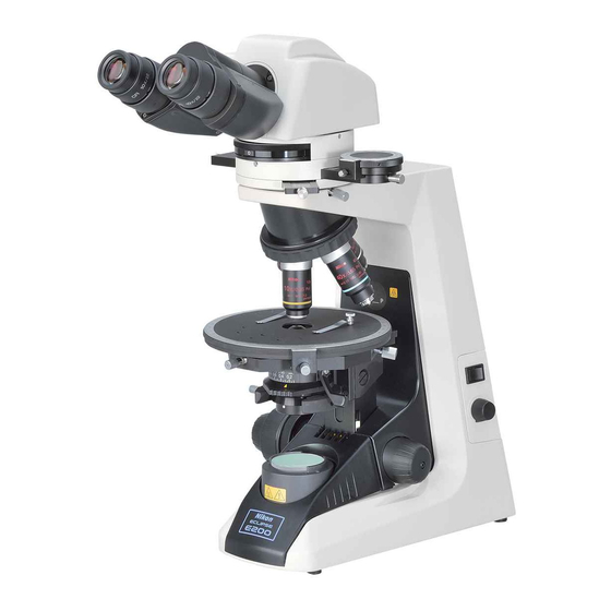
Nomenclature of Each Part The microscope is made up of the following components. (1) Basic unit (2) Eyepieces (3) Eyepiece tube (4) Objectives Objectives with various magnifying powers are available. (5) Condenser Used for condensing light. The condenser should be positioned slightly lower than its upper limit. - Page 11 Nomenclature of Each Part (2) Eyepieces (3) Eyepiece tube (6) Polarizing intermediate tube (1) Basic unit (4) Objectives (10) Fuse (x2) (5) Condenser (7) Polarizer (8) Field lens unit (11) Power cord (9) Lamp...
-
Page 12: Switches And Controls
Switches and Controls (1) Diopter ring (12) P-CL 1/4 λ and tint plate (21) Condenser top lens Adjust the diopter ring to Insert into the polarizing swing-out knob compensate for the intermediate tube. Used to swing-out the top difference between your lens of the condenser. - Page 13 Switches and Controls (1) Diopter ring (12) P-CL 1/4 λ and tint plate (13) Eyepiece tube (2) Bertrand lens turret clamp screw (3) Bertrand lens focus ring (14) Analyzer slider (15) Intermediate tube clamp screw (4) Revolving nosepiece (5) Standard screw hole mark (16) Orientation plate (6) Specimen clip (17) Circular graduated...
-
Page 14: Iiia Quick Microscopic Procedure
A Quick Microscopic Procedure Turn on the lamp and adjust Focus with 10x objective. interpupillary distance. Turn on the power switch. Match the bottom edge of the diopter ring Push the analyzer slider left. with the engraved base line. Turn to position “0”. Place specimen slide on the stage. -
Page 15: Adjust The Diopter
A Quick Microscopic Procedure Magnify the image and Adjust the diopter. observe! Use your right eye. Check the magnifying power. And focus on the crosshairs with this ring. Use your right eye. Move the ring to the 70-80% of the objective. N.A. -
Page 16: Microscopy (Detailed Procedure)
Microscopy (Detailed Procedure) Lamp Illumination Turn on the power switch (turn to |) and the lamp will come on. Turn the brightness control dial to Power ON adjust the brightness of the viewfield. (Turning the dial clockwise increases the brightness; turning the Darkens. - Page 17 Microscopy (Detailed Procedure) Replacing a Specimen Using the Refocusing Mechanism Try focusing on the specimen with 40x or higher magnification objective. You will find the specimen is brought very near to the objective. It will be very difficult to change the specimen without moving the focus knob.
- Page 18 Microscopy (Detailed Procedure) Focus with the 10x Objective Rotate the revolving nosepiece to bring the 10x objective into the optical path. (The objective will click into place when rotated into position.) Bring the specimen image into focus by turning the coarse focus and then fine focus knob.
- Page 19 Microscopy (Detailed Procedure) Focusing Turning the focus knobs recklessly is a long and hard way to focus on the image. If you are using a high power objective, you may even damage the specimen by pressing it against the objective. Before breaking the coverglasses or damaging the objectives, read the following and find the correct way to focus on the specimen.
- Page 20 Microscopy (Detailed Procedure) Using the Working Distance for Focusing Each objective has its working distance indicated on its side. The working distance is the distance between the front of the objective and the specimen when the specimen image is in focus. If you have difficulties in focusing with the standard procedure described on p.
- Page 21 Microscopy (Detailed Procedure) Eyepiece Diopter Adjustments Adjust the diopter rings on the eyepieces according to the difference between your left and right eyesight. This adjustment enables the user to take full advantage of the high-quality objectives, including their parfocality. Method 1: When using an eyepiece with crosshairs Slightly lower the condenser from its uppermost position.
- Page 22 Microscopy (Detailed Procedure) Method 2: When there is no crosshairs on your eyepiece. Slightly lower the condenser from its uppermost position. (1) Swing the 40x objective in the optical path. Rotate the coarse and then fine focus knobs to bring the specimen in focus. (2) Switch back to the 10x (or 4x) objective.
-
Page 23: Aperture Diaphragm Adjustment
Microscopy (Detailed Procedure) Aperture Diaphragm Adjustment Orthoscopic Microscopy The aperture diaphragm is important because it is related to the resolution, contrast, depth of focus and brightness of the optical image. Numerical Turning the condenser aperture diaphragm ring aperture changes the size of the aperture diaphragm. 0.65 As the aperture diaphragm is stopped down, resolution and brightness are reduced while... - Page 24 Microscopy (Detailed Procedure) Conoscopic Microscopy In the case of conoscopic microscopy, the condenser aperture diaphragm functions as a field diaphragm on the conoscopic image surface. Stop down the diaphragm until it circumscribes the circumference of the field of view of the conoscopic image (pupil of the objective). Orthoscopic Observation/Conoscopic Observation The following provides an explanation of the characteristic observation method of polarizing microscopes along with the microscopy procedure.
- Page 25 Microscopy (Detailed Procedure) The settings of each part in orthoscopic microscopy and conoscopic microscopy are summarized below. Orthoscopic Observation Conoscopic Observation To investigate the vibration direction To distinguish between uniaxial and birefringence of observation and biaxial properties and Purpose of light by observing the extinction and observe the optic-axial angle observation...
- Page 26 Microscopy (Detailed Procedure) Orientation of Polarizing Plates (Polarizer and Analyzer) (1) Push in the analyzer slider to the right and move the analyzer out of the optical path. (2) Focus on the specimen. (3) Pull out the analyzer knob and move the analyzer into the optical path.
- Page 27 Microscopy (Detailed Procedure) The analyzer can be rotated by first loosening the Rotation ring analyzer clamp screw and then turning the rotation ring . The angle of rotation can be read to 0.1 degrees over a range of 0-360 degrees with the vernier.
- Page 28 Microscopy (Detailed Procedure) Circular Graduated Stage for Polarizing Microscope Loosening the stage rotation clamp screw can rotate the stage. The angle of rotation can be read to 0.1 degrees using the vernier. Centering the stage (1) Focus on the specimen with 10x objective. Remove the analyzer from the optical path.
- Page 29 Microscopy (Detailed Procedure) P-CS Sénarmont Compensator The P-CS Sénarmont compensator is used by inserting into the slot of the intermediate tube in place of the P-CL 1/4λ & tint plate. It can be used to measure retardation up to 1λ according to the following procedure.
- Page 30 Microscopy (Detailed Procedure) P-CQ Quartz Wedge The P-CQ quartz wedge is used by inserting it into the slot of the intermediate tube in place of the P-CL 1/4λ & tint plate. The quartz wedge is engraved with a scale and can be used for rough measurement of retardation in the range of 1λ-6λ.
- Page 31 Microscopy (Detailed Procedure) Trinocular Eyepiece Tube Optical path selection The optical path selection lever can be used to select the way to divide the amount of light between the binocular part and the vertical tube. Light proportion Lever Position Binocular part : Vertical tube Push in.
- Page 32 Microscopy (Detailed Procedure) Turning Off the Lamp Turning off the power switch (turn to ) switches off the lamp. When storing the microscope: • Unplug the power cord. • Wait until the field lens unit is cool enough to touch. •...
-
Page 33: Miscellaneous Operations
Miscellaneous Operations Oil-Immersion Observation The “Oil” mark on the side of an objective indicates that it is an oil-immersion type objective. (The oil-immersion objective also has a black band around the barrel end.) An oil-immersion objective is used with the immersion oil applied between the front of the objective and the coverglass. -
Page 34: Adjusting The Torque Of The Coarse Focus Knob
• If you find an oil drips around the container, wipe them off. • Avoid contact of immersion oil with eyes or skin. In the event of contact with eyes or skin, take one of the following measures although Nikon immersion oil does not contain any toxic ingredients. -
Page 35: Upper Limit Bolt
V Miscellaneous Operations 3 Upper Limit Bolt Upper Limit Bolt The upper limit bolt is used to prevent the specimen touching the objective when a 40x or larger-power objective (objectives with a small working distance) is used. Using the upper limit bolt, the stage does not move up from a certain position. -
Page 36: Assembly
If the voltage indication on the nameplate differs: Do not plug in the microscope. Contact your nearest Nikon representative. If the voltage indication above the AC inlet differs: Change the input voltage setting before turning on the power switch. -
Page 37: Removal Of Shipping Clamps
VI Assembly 1 Assembly Changing the Voltage Setting (1) Turn off the power switch (turn to ) and Fuse holder unplug the power cord. (2) Remove the fuse holder using the flatblade precision screwdriver. (Use the tip of the screwdriver to push the two lock plates toward the center of the fuse holder. -
Page 38: Attaching The Intermediate Tube
VI Assembly 1 Assembly Attaching the Intermediate Tube Fully loosen the eyepiece tube clamp screw on the microscope arm. Tilt the intermediate tube and fit it on the circular mount of the microscope arm so that the positioning pin on the intermediate tube matches the positioning groove on the mount. -
Page 39: Attaching The Analyzer Slider
VI Assembly 1 Assembly Eyepieces Use the eyepieces with the same magnification for Positioning pin both eyes. On the right sleeve, attach the eyepiece with crosshairs. Insert the eyepiece into the sleeve matching the grooves on the eyepiece with the positioning projections on the sleeve. -
Page 40: Attaching The Condenser
VI Assembly 1 Assembly Attaching the Condenser Lower the condenser holder to the limit using the condenser focus knob. Insert the condenser to the condenser holder so that its nameplate faces forward. Fix the condenser by tightening the condenser clamp screw at the left side. Raise the condenser till the limit. -
Page 41: Replacement Of Consumable Materials
VI Assembly 2 Replacement of Consumable Materials Replacement of Consumable Materials Replacing the Lamp WARNING • To avoid electrical shock or damage to the instrument, turn off the power switch (turn to ) and unplug the power cord before lamp replacement. - Page 42 VI Assembly 2 Replacement of Consumable Materials (1) Turn off the power switch (turn to ) and unplug the power cord. (2) Wait about 30 minutes until the lamp and its surroundings are cool enough to touch. (3) Hold the field lens unit at the vertical grooves on both sides and pull it toward you to remove it.
-
Page 43: Replacing The Fuse
VI Assembly 2 Replacement of Consumable Materials Replacing the Fuse WARNING • To avoid electrical shock or damage to the instrument, turn off the power switch (turn to ) and unplug the power cord before replacing the fuse. • Use the specified fuse. Using a different fuse may damage the instrument or cause a fire hazard. -
Page 44: Optical Characteristics
Optical Characteristics Combinations of 10x Eyepiece with CFI P Objectives Objective Total Numerical Real Viewfield* Depth of Resolving Working Magnification Magnification Aperture Focus Power Distance 63.2 µm 2.8 µm 4× 40× 5.5 mm(5 mm) 30 mm 10× 100× 0.25 2.2 mm(2 mm) 10.1 µm 1.1 µm 6.1 mm... - Page 45 VII Optical Characteristics (7) Depth of Focus The depth (thickness) of the specimen image in focus, extending above and below the focused image plane. The larger the N.A. of the objective, the shallower the depth of focus. λ Depth of focus [µm] = +...
-
Page 46: Troubleshooting Tables
If difficulties should be encountered in the course of operation, please recheck the symptoms, referring to the tables below, before contacting your nearest Nikon representative. If the problem is still not solved after referring to Troubleshooting Tables, please contact your nearest Nikon representative. - Page 47 No cover glass attached to the Attach a cover glass 0.17 mm slide. thick. No immersion oil used on the Apply Nikon immersion oil to the front lens of the oil-immersion objective. (P. 31) objective. Nikon immersion oil is not used Use Nikon immersion oil.
- Page 48 VIII Troubleshooting Tables 1 Optical Troubles Causes Corrective Measures Image not focused on one Revolving nosepiece not in Revolve to click-stop position. side. click-stop position. Specimen rises from stage Stabilize it using the specimen surface. clips. Troubles Causes Corrective Measures Image shifts during focus.
- Page 49 VIII Troubleshooting Tables 2 Mechanical Problems Mechanical Problems Troubles Causes Corrective Measures Image cannot be focused Slide upside down. Turn over the slide so that the with high-power objectives. cover glass faces up. Cover glass too thick. Use a cover glass of the specified thickness (0.17 mm).
- Page 50 VIII Troubleshooting Tables 3 Electrical Problems Electrical Problems Troubles Causes Corrective Measures Lamp does not light when No electrical power. Check power cord connection. switched on. (P. 38) No power cord connected to Plug in the power cord to the AC microscope.
-
Page 51: Care And Maintenance
• We especially recommend that the objectives and eyepieces be kept in a container (such as a desiccator) with desiccant in it. Periodical Inspections • To maintain the performance of the microscope, periodical inspections and maintenance are recommended. • For details, contact your nearest Nikon representative. - Page 52 Technical (1) Model Name: ECLIPSE E200 POL (Microscope basic unit) (2) Dimension and 227(W) x 382(D) x 415(H) mm, 10 kg Weight: (3) Optical System: CF infinity corrected optical system Second objective focal length f = 200 mm Built-in diascopic illumination system (Simplified Kohler ユ s illumination...
-
Page 53: Technical Specifications
X Technical Specifications Model for 220, 230, 240 V Areas • Input voltage: Select from 220 V, 230 V or 240 V AC by relocating the fuse holder in the AC inlet. • Frequency: 50/60 Hz • Voltage fluctuation: ±10% •...
Need help?
Do you have a question about the ECLIPSE E200 POL and is the answer not in the manual?
Questions and answers