Table of Contents
Advertisement
Advertisement
Table of Contents

Related Manuals for Nikon eclipse e100


Summary of Contents for Nikon eclipse e100
- Page 1 M413 E 06.10.NF.1 Microscope ECLIPSE E100 Instructions...
- Page 3 Thank you for purchasing this Nikon product. This instruction manual is for the users of the Nikon Microscope ECLIPSE E100 describing basic operation of the microscope. To ensure correct usage, please read this manual thoroughly before using the microscope. • It is prohibited to reproduce or transmit this manual in any form without the prior consent of Nikon.
-
Page 4: Warning And Caution Symbols Used In This Manual
Warning and Caution Symbols Used in This Manual Though Nikon products are designed to provide you with utmost safety during use, incorrect usage or disregard of the instructions may cause personal injury or property damage. For your own safety, read the instruction manual carefully and thoroughly before using the product. -
Page 5: Common Sense Safety Instructions
There are no user serviceable parts inside the microscope. Disassembly will void the warranty, and could degrade the performance, cause electrical shock or personal injury, or damage the instrument. If you have a service problem, contact your nearest Nikon representative. WARNING 3. - Page 6 ) and unplug the power cord. Then, wipe off the water with a dry cloth. Short circuiting can also result when foreign matter is trapped inside the microscope. If foreign matter or water has entered the microscope, do not use the microscope and contact your nearest Nikon representative. CAUTION 7.
- Page 7 9. Installation This microscope is a precision instrument. Using the microscope in an unfavorable environment could result in malfunctions or degraded performance. Consider the following conditions when choosing the installation location. • Observation conditions are better if light from windows and bright room light can be avoided. •...
- Page 8 12. Focus Knobs Do not turn the right and left focus knobs simultaneously in opposite directions. Do not turn the coarse focus knob any further after the stage has been moved up or down to its limit. These operations will damage the focusing mechanism.
-
Page 9: Table Of Contents
Contents Warning and Caution Symbols Used in This Manual Symbols Labeled on the Product Common Sense Safety Instructions Nomenclature of Each Part Switches and Controls III. A Swift Microscopic Procedure IV. Microscopy (Detailed Procedure) Miscellaneous Operations 1. Oil-Immersion Observation 2. Adjusting the Torque of the Coarse Focus Knob 3. -
Page 10: Nomenclature Of Each Part
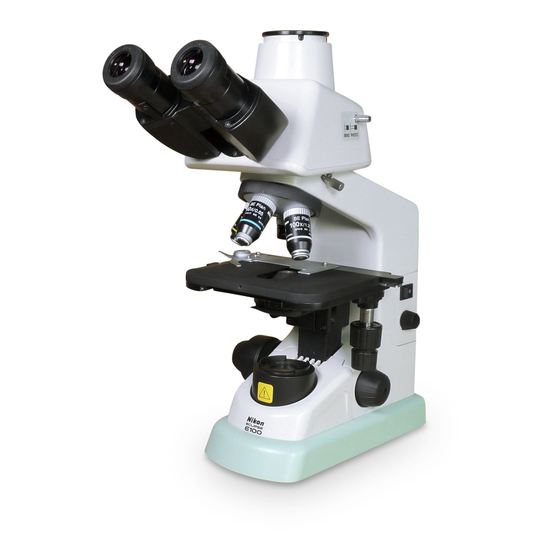
Nomenclature of Each Part The microscope is made up of the following components. Basic unit Eyepieces Screwed on to the eyepiece tube. Eyepiece tube This is a binocular eyepiece tube. A trinocular eyepiece tube is available for photomicrography and TV microscopy. Amonocular eyepiece tube can be used also. Objectives Objectives with various magnifying powers are available. - Page 11 2 Eyepieces 3 Eyepiece tube 1 Basic unit 4 Objectives 8 Fuse (x2) 5 Condenser 9 Power cord 6 Field lens unit 7 Lamp...
-
Page 12: Switches And Controls
Switches and Controls Diopter ring Condenser vertical motion lever Adjust the diopter ring to compensate for Use this lever to adjust the vertical the difference between your right and left position of the condenser. (p. 19) eyesight. (p. 18) This lever is located either on the right or the left side of the stage. - Page 13 1 Diopter ring 7 Stage 2 Revolving nosepiece 3 Specimen holder 8 Power switch 9 Brightness control dial 4 Magnifying power indication ring 10 Longitudinal stage motion (Y Axis) knob 5 Condenser aperture diaphragm lever 11 Lateral stage motion (X Axis) knob 6 Blue filter and the 12 Fine focus knob filter holder...
-
Page 14: A Swift Microscopic Procedure
A Swift Microscopic Procedure Turn on the lamp and adjust Focus with 10x objective. interpupillary distance. Turn on the power switch. Match the bottom edge of the diopter Widen or narrow to merge ring with the the viewfields into one. engraved base line. -
Page 15: Adjust The Diopter
Magnify the image and Adjust the diopter. observe! Repeat the steps twice. Switch to the 40x. Check the magnifying power. Focus with this knob. Move the lever to the Switch back to the 10x. magnifying power of the Use your right eye. objective. -
Page 16: Microscopy (Detailed Procedure)
Microscopy (Detailed Procedure) Lamp Illumination Turn on the power switch (turn to |) and the Power ON lamp will come on. Turn the brightness control dial to adjust the brightness of the viewfield. (Turning the dial clockwise increases the brightness; turning the dial counterclockwise decreases it.) Darkens. - Page 17 4) Specimen Mounting Place specimen slide on the stage with the coverglass facing upward. Open the claw of the specimen holder with your finger at the root tilt and fix the specimen slide with the claw. Coverglass 5) Focus with the 10x Objective Rotate the revolving nosepiece to bring the 10x objective into the optical path.
- Page 18 Focusing Turning the focus knobs recklessly is a long and hard way to focus on the image. If you are using a high power objective, you may even damage the specimen by pressing it against the objective. Before breaking the coverglasses or damaging the objectives, read the following and find the correct way to focus on the specimen.
- Page 19 Using the Working Distance for Focusing Each objective has its working distance indicated on its side. The working distance is the distance between the front of the objective and the specimen when the specimen image is in focus. If you have difficulties in focusing with the standard procedure described on p. 16, try one of the following methods using the working distance for focusing.
- Page 20 6) Eyepiece Diopter Adjustments Adjust the diopter ring on the eyepiece tube according to the difference between your left and right eyesight. This adjustment enables the user to take full advantage of the high-quality objectives, including their parfocality. (1) Swing the 40x objective in the optical path.
- Page 21 7) Condenser Vertical Position Adjustment Use the condenser vertical motion lever to move up the condenser till it touches the limit. Then, slightly lower the condenser. If you should see the diffuser image on the viewfield background, slightly move up or down the condenser till the diffuser image disappears.
-
Page 22: Adjusting The Aperture Diaphragm
Adjusting the Aperture Diaphragm The aperture size is increased or decreased by rotating the condenser aperture diaphragm lever. If the aperture diaphragm is closed, the brightness and resolution are decreased but the contrast and range of focus are increased. If the aperture diaphragm is opened, the brightness and resolution are increased but the contrast and range of focus are decreased. - Page 23 10) Turning Off the Lamp Turning off the power switch (turn to ) switches off the lamp. When storing the microscope: • Unplug the power cord. • Wait until the field lens unit is cool enough to touch. • Cover the microscope with the vinyl dust cover. (Before covering the microscope, make sure that the field lens unit is cool enough to touch.) •...
-
Page 24: Miscellaneous Operations
Miscellaneous Operations Oil-Immersion Observation The “Oil” mark on the side of an objective indicates that it is an oil-immersion type objective. (The oil-immersion objective also has a black band around the barrel end.) An oil-immersion objective is used with the immersion oil applied between the front of the objective and the coverglass. For an oil-immersion objective with a numerical aperture of 1.0 or more, use of an oil-immersion type condenser is required to take full advantage of its performance. - Page 25 • If you find an oil drips around the container, wipe them off. • Avoid contact of immersion oil with eyes or skin. In the event of contact with eyes or skin, take one of the following measures although Nikon immersion oil does not contain any toxic ingredients.
-
Page 26: Adjusting The Torque Of The Coarse Focus Knob
Adjusting the Torque of the Coarse Focus Knob The tension (torque) of the coarse focus knob rotation can be adjusted. To increase the tension, turn the coarse focus knob torque adjustment ring counterclockwise. The torque Loosens. adjustment ring is located at the back of the coarse focus knob. -
Page 27: Assembly
Assembly Read the “Common Sense Safety Instructions” in this manual before assembling the microscope. Be sure to follow the instructions written therein. Also, make sure that the power switch is off (turned to ) before assembly to prevent electrical shock. Tools Required for Assembly Hexagonal wrench (one hexagonal wrench is provided with the microscope and the eyepiece tube), flatblade precision screwdriver... -
Page 28: Assembly Of Standard Set
If the voltage indication on the nameplate differs: Do not plug in the microscope. Contact your nearest Nikon representative. Input Voltage Indications If the voltage indication above the AC-IN socket differs: Change the input voltage setting before turning on the power switch. - Page 29 2) Removal of Shipping Clamps The stage top plate and focusing mechanism are clamped for protection against vibration and shocks during transportation. Remove these shipping clamps with the hexagonal wrench provided. • Stage Top Plate: The top plate of the stage is retained in the Y-axis direction by a plate fastened with two bolts.
-
Page 30: Assembly Of Additional Components
5) Connecting the Power Cord Turn off the power switch of the microscope (turn to ). Connect one end (socket) of the supplied power cord to the AC-IN socket on the rear of the microscope. Connect the other end (plug) to an AC line receptacle with the ground conductor (earth conductor). Make sure that the power cord is securely connected. -
Page 31: Objectives
2) Objectives Objectives are attached to the microscope before shipment. When replacing an objective, remove the specimen from the stage and lower the stage. Remove the objective holding it with both hands. Be careful not to drop the objective. Screw a new objective into the revolving nosepiece. Set the objectives in such an order that the objective magnification increases as the revolving nosepiece is turned clockwise (as viewed from the top of the microscope). -
Page 32: Replacement Of Consumable Materials
Replacement of Consumable Materials 1) Replacing the Lamp WARNING • To avoid electrical shock or damage to the instrument, turn off the power switch (turn to ) and unplug the power cord before lamp replacement. • Use the specified lamp. Using a different kind of lamp may damage the instrument or cause a fire hazard. -
Page 33: Replacing The Fuse
(1) Turn off the power switch (turn to ) and unplug the power cord. (2) Wait about 30 minutes until the lamp and its surroundings are cool enough to touch. (3) Hold the field lens unit at the dents on both sides and pull it upward slowly while slightly moving laterally to remove it. - Page 34 CAUTION • Make sure that the contact of the fuse is not damaged before installing a new fuse. If the contact is damaged, a malfunction or overheating may result. • Attach the fuse to the fuse holder securely. If not, the fuse may come loose or a contact failure may occur, resulting in overheating or smoke.
-
Page 35: Optical Characteristics
Optical Characteristics Combinations of 10x (Field No. 18) Eyepiece with Objectives Objective Total Numerical Real Depth of Resolving Working Magnification Magnification Aperture Viewfield Focus Power Distance Microscope Terminology (1) Total Magnification The total magnification of a microscope is the individual magnifying power of the objective multiplied by that of the eyepiece. - Page 36 (5) Field Number of the Eyepiece The diameter of the opening of the fieldstop inside the eyepiece measured in mm. When an eyepiece has an indication of “10x / 18”, it means that the magnification is 10x and the field number is 18 for that eyepiece. (6) Real Viewfield The diameter in mm of the field of view observable through the eyepiece.
-
Page 37: Troubleshooting Tables
Troubleshooting Tables If difficulties should be encountered in the course of operation, please recheck the symptoms, referring to the tables below, before contacting your nearest Nikon representative. Optical Troubles Causes Corrective Measures Revolving nosepiece not in Revolve to click-stop position... - Page 38 No immersion oil used on the Apply Nikon immersion oil to front lens of the oil-immersion the objective. (P. 22) objective. Nikon immersion oil is not used for oil-immersion observation. Air bubbles in immersion oil. Remove bubbles. (P. 22) Immersion oil found on dry type Clean the objective.
- Page 39 Troubles Causes Corrective Measures Revolving nosepiece not in Revolve to click-stop position. Image dark on one side. click-stop position. Specimen rises from stage Stabilize it using the holder. surface. Revolving nosepiece not in Revolve to click-stop position. Image shifts during focus. click-stop position.
- Page 40 Mechanical Problems Troubles Causes Corrective Measures Slide upside down. Turn over the slide so that the Image cannot be focused cover glass faces up. with high-power objectives. Cover glass too thick. Use a cover glass of the specified thickness (0.17 mm). Slide upside down.
- Page 41 Electrical Problems Troubles Causes Corrective Measures No electrical power. Check power cord connection. Lamp does not light when (P. 28) switched on. Power cord not connected to Connect the power cord to the the microscope. AC-IN socket. (P. 28) Lamp bulb not inserted. Insert correctly.
-
Page 42: Care And Maintenance
• We especially recommend that the objectives and eyepieces be kept in a container (such as a desiccator) with desiccant in it. Periodical Inspections • To maintain the performance of the microscope, periodical inspections and maintenance are recommended. • For details, contact your nearest Nikon representative. -
Page 43: Specifications
Specifications (1) Model Name: ECLIPSE E100 (Microscope basic unit) (2) Optical System: CFI optical system (infinity - corrected CF optical system) 2nd objective lens focal length : f = 200 mm Built-in diascopic illumination system (Simplified Kohler’s illumination system) (3) Focusing Mechanism: Fine focus knob graduation: 2 µm/graduation... - Page 44 Model for 220, 230, 240 V AC Areas Input voltage: Select from 220 V, 230 V or 240 V AC by relocating the fuse holder in the AC inlet. Frequency: 50 - 60 Hz Voltage fluctuation: ±10% Rated current: 0.3 A Fuse rating: 250 V, 0.5A, time-lag low-breaking type, 5 x 20 miniature fuse x 2...
Need help?
Do you have a question about the eclipse e100 and is the answer not in the manual?
Questions and answers