Table of Contents
Advertisement
Available languages
Available languages
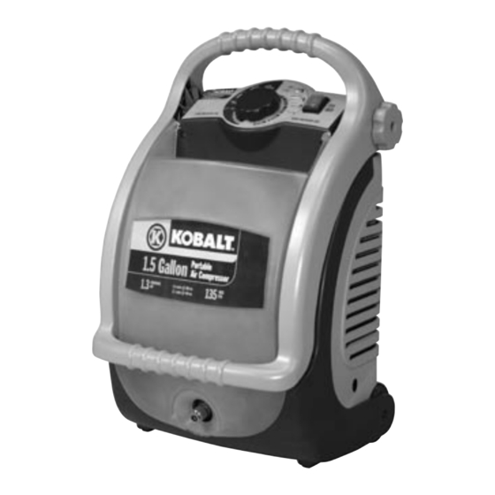
ITEM/ARTICULO #234955
MODEL/MODELO #K13015F
Operator's Manual and Parts List
Manual del Operador y Lista de las Piezas
(pag. 15)
Oilless, Single Stage, Direct Drive,
Electric Air Compressor
WARNING: Read and understand all safety precautions in this manual before operating. Failure to comply with
instructions in this manual could result in personal injury, property damage, and/or voiding of your warranty.
The manufacturer WILL NOT be liable for any damage because of failure to follow these instructions.
Printed in China
K13015FOM_Ver.0406
Advertisement
Chapters
Table of Contents

Related Manuals for Kobalt K13015F


Summary of Contents for Kobalt K13015F
- Page 1 ITEM/ARTICULO #234955 MODEL/MODELO #K13015F Operator’s Manual and Parts List Manual del Operador y Lista de las Piezas (pag. 15) Oilless, Single Stage, Direct Drive, Electric Air Compressor WARNING: Read and understand all safety precautions in this manual before operating. Failure to comply with instructions in this manual could result in personal injury, property damage, and/or voiding of your warranty.
-
Page 2: Table Of Contents
TABLE OF CONTENTS SAFETY GUIDELINES ..................................3 FEATURES - Product specifications ..............................4 ELECTRICAL POWER REQUIREMENTS ............................5 OVERVIEW ......................................6 GLOSSARY OF TERMS ..................................6 ASSEMBLY ......................................7 OPERATION ......................................9 MAINTENANCE ....................................11 TROUBLESHOOTING CHART ................................11 PARTS DIAGRAM ....................................12 PARTS LIST ....................................... -
Page 3: Safety Guidelines
SAFETY GUIDELINES The following information relates to protecting YOUR SAFETY and PREVENTING EQUIPMENT PROBLEMS. To help you recognize this information, we use the following symbols. Please read the manual and pay attention to these sections. DANGER: - A POTENTIAL HAZARD THAT WILL CAUSE SERIOUS INJURY OR LOSS OF LIFE. WARNING: - A POTENTIAL HAZARD THAT COULD CAUSE SERIOUS INJURY OR LOSS OF LIFE. -
Page 4: Features - Product Specifications
FEATURES PRODUCT SPECIFICATIONS Lubrication ..............Oil-Free Running Horsepower ............1.3 HP Adjustable Air Outlet ........from 40 to 135 PSI Air Tank Capacity ............1.5 gal. Gauges ...............1.5 in. diameter Air Pressure ............135 psi max. Input ........120 V, 60 Hz, AC only, 12 Amps Air Delivery .......... -
Page 5: Electrical Power Requirements
ELECTRICAL POWER REQUIREMENTS EXTENSION CORDS GROUNDING INSTRUCTIONS Use only 3-wire extension cords that have 3-prong grounding In the event of a malfunction or breakdown, grounding provides plugs and 3-pole receptacles that accept the air compressor’s plug. a path of least resistance for electric current to reduce the risk of When using the air compressor at a considerable distance from electric shock. -
Page 6: Overview
OVERVIEW BASIC AIR COMPRESSOR COMPONENTS The pump compresses the air and discharges it into the tank. The tank stores the compressed air. Oilless air compressors are factory lubricated for life and do The control panel of the compressor consists of the ON/OFF not require any oil. -
Page 7: Assembly
ASSEMBLY FEATURES WARNING: To prevent accidental starting that could KNOW YOUR AIR COMPRESSOR (See Fig. A, p. 4) cause serious personal injury, always unplug the tool when Before attempting to use this product, familiarize yourself with all assembling parts. operating features and safety rules. AIR OUTLET 2) ASSEMBLING THE HANDLE The air outlet is located on the front of the compressor. - Page 8 ASSEMBLY Fig. 7 Pic. 4 Pic. 5 Fig. 8 Pic. 6 4) ATTACHING HOSE TO COMPRESSOR (See Fig. 7 - 9) • Make sure the air compressor is off and unplugged. • Apply seal thread tape to both ends of the coil hose. •...
-
Page 9: Operation
OPERATION WARNING: Do not allow familiarity with tools to make you careless. Remember that a careless fraction of a second is sufficient to inflict serious injury. Always wear safety goggles or safety WARNING: glasses with side shields when operating power tools. Failure to do so could result in objects being thrown into your eyes resulting in possible serious injury. - Page 10 OPERATION HOW TO USE THE SWIVEL HANDLE The handle is designed to be used in two different positions. • To lift up the compressor, use the handle in the ‘closed’ position (Pic. 1). Be sure the 2 handle knobs are well tightened.
-
Page 11: Maintenance
MAINTENANCE WARNING: When servicing, use only identical Kobalt Most plastics are susceptible to damage from various types replacement parts. Use of any other parts may create a hazard of commercial solvents. Do not use solvents when cleaning plastic or cause product damage. -
Page 12: Parts Diagram
PARTS DIAGRAM 21 32 K13015FOM_Ver.0406... - Page 13 PARTS DIAGRAM 70 67 K13015FOM_Ver.0406...
-
Page 14: Parts List
PARTS LIST COMPRESSOR PUMP ITEM CODE DESCRIPTION ITEM CODE DESCRIPTION 9413190040 TANK 9415090 GROUP MOTOR/CRANKCASE 9415089 PUMP OL195S A631000 CYLINDER BARREL 9115011 SCREW M6X16 A610101 CONROD/PISTON 9038274 FRONT PANEL UL 9040019 SEAL RING 9038275 REAR PANEL UL 9415053 CONROD COVER 9038276 HANDLE 9011004... -
Page 15: K13015Fom_Ver
ARTICULO #234955 MODELO #K13015F Manual del Operador y Lista de las Piezas Sin aciete, de una sola etapa, de mando directo, compresor de aire eléctricos ADVERTENCIA: Lea y comprenda todas las precauciones de seguridad contenidas en este manual antes de utilizar esta unidad. - Page 16 INDICE PAUTAS DE SEGURIDAD ................................. 17 CARACTERÍSTICAS - Especificaciones del producto ........................18 REQUERIMIENTOS DE ALIMENTACIÓN ELÉCTRICA ........................19 RESUMEN GENERAL ..................................20 GLOSARIO DE TÉRMINOS ................................20 MONTAJE ......................................21 FUNCIONAMIENTO ..................................23 MANTENIMIENTO ....................................25 SOLUCIÓN DE PROBLEMAS ................................26 ESQUEMA DE LAS PIEZAS ................................
-
Page 17: Pautas De Seguridad
PAUTAS DE SEGURIDAD La información que sigue se refiere a la protección de SU SEGURIDAD y la PREVENCIÓN DE PROBLEMAS DEL EQUIPO. Como ayuda para reconocer esta información, usamos los siguientes símbolos. Lea por favor el manual y preste atención a estas secciones. PELIGRO: - UN POSIBLE RIESGO QUE CAUSARÁ... -
Page 18: Características - Especificaciones Del Producto
CARACTERÍSTICAS ESPECIFICACIONES DEL PRODUCTO Lubricación ..........Lubricación permanente Potencia de funcionamiento ..........1,3 HP Toma de aire ajustable ........... 40 a 135 PSI Capacidad del tanque de aire ....... 5,3 lt (1,5 gal) Manómetros ....... 38 mm (1,5 pulg.) de diámetro Presión de aire ........931 kPa (135 psi) máx. Corriente de entrada .... -
Page 19: Requerimientos De Alimentación Eléctrica
REQUERIMIENTOS DE ALIMENTACIÓN ELÉCTRICA CORDONES DE EXTENSIÓN del motor. Una línea destinada sólo para luces no puede alimentar Sólo utilice cordones de extensión de tres conductores con el motor de una herramienta eléctrica. El cable con el calibre clavijas de tres patillas y receptáculos de tres polos que acepten suficiente para una distancia corta será... -
Page 20: Resumen General
RESUMEN GENERAL COMPONENTES BÁSICOS motor se enfríe lo suficiente, volverá a arrancar automáticamente. DEL COMPRESOR DE AIRE La bomba comprime el aire y lo descarga hacia el tanque. EI tanque almacena el aire comprimido. Los compresores de aire sin aceite se lubrican en fábrica para El panel de control del compresor consiste en el botón de toda su vida útil, y no requieren aceite. -
Page 21: Montaje
MONTAJE CARACTERÍSTICAS la herramienta al montarle piezas a aquélla. FAMILIARÍCESE CON EL COMPRESOR (Vea la Fig. A, p. 18) Antes de intentar utilizar este producto, familiarícese con todas 2) MONTAJE DE LA MANIJA las características de funcionamiento y normas de seguridad de Levante levemente la manija y bájela hasta el cuerpo del la unidad. - Page 22 Foto 6 K13015FOM_Ver.0406...
-
Page 23: Funcionamiento
FUNCIONAMIENTO ADVERTENCIA: No permita que su familarización con las herramientas lo vuelva descuidado. Tenga presente que un descuido de un instante es suficiente para causar una lesión grave. Cuando utilice herramientas eléctricas, ADVERTENCIA: póngase siempre gafas de seguridad o anteojos protectores con protección lateral. - Page 24 FUNCIONAMIENTO CÓMO USAR LA MANIJA GIRATORIA La manija está diseñada para usarse en dos posiciones diferentes. • Para levantar el compresor, coloque la manija en la posición ‘cerrada’ (Foto 1). Asegúrese de que las 2 perillas de la manija estén bien apretadas. •...
-
Page 25: Mantenimiento
Al dar servicio a la unidad, sólo utilice La mayoría de los plásticos son susceptibles a diferentes tipos piezas de repuesto Kobalt idénticas. El empleo de piezas de solventes comerciales. Evite el empleo de solventes al limpiar diferentes puede causar un peligro o dañar el producto. -
Page 26: Solución De Problemas
SOLUCIÓN DE PROBLEMAS PROBLEMA CAUSA SOLUCIÓN 1) Recalentamiento o pérdida de potencia 1) Verifique que el cordón de extensión esté usándose de forma correcta. 2) No hay corriente eléctrica 2) Revise para asegurarse de que esté conectada la unidad. Revise fusible, disyuntor o protector contra sobrecarga térmica 3) Fusible fundido en el taller o casa 3) Reemplace el fusible fundido del taller o casa El compresor no... -
Page 27: Esquema De Las Piezas
ESQUEMA DE LAS PIEZAS 21 32 K13015FOM_Ver.0406... - Page 28 ESQUEMA DE LAS PIEZAS 70 67 K13015FOM_Ver.0406...
-
Page 29: Lista De Las Piezas
LISTA DE LAS PIEZAS COMPRESOR BOMBA CODE DESCRIPCIÓN CANT CODE DESCRIPCIÓN CANT 9413190040 DEPÓSITO 9415090 CÁRTER 9415089 BOMBA OL195S A631000 CILINDRO MECA A610101 BIELA 9115011 TORNILLO M6X16 9040019 TORICA 9038274 PANEL FRONTAL UL 9415053 TAPÓN BIELA 9038275 PANEL POSTERIOR AZUR UL 9011004 TORNILLO TORX M5X16 9038276... - Page 30 K13015FOM_Ver.0406...
- Page 31 K13015FOM_Ver.0406...
- Page 32 9415147...
Need help?
Do you have a question about the K13015F and is the answer not in the manual?
Questions and answers