Gaggia Brera Service Manual
Hide thumbs
Also See for Brera:
- User manual ,
- Operating instructions manual (89 pages) ,
- Manual (3 pages)
Table of Contents
Advertisement
All parts of this document are the property of Saeco International Group.
All rights reserved. This document and all the information herein is provided without liability deriving
from any errors or omissions. Furthermore, no part may be reproduced, used or collected, except where
express authorisation has been provided in writing or through a contractual agreement.
SERVICE
MANUAL
Revision 00
Rev. 00 / OCTOBER 2009
Advertisement
Table of Contents

Subscribe to Our Youtube Channel
Related Manuals for Gaggia Brera


Summary of Contents for Gaggia Brera
- Page 1 SERVICE MANUAL Revision 00 All parts of this document are the property of Saeco International Group. All rights reserved. This document and all the information herein is provided without liability deriving from any errors or omissions. Furthermore, no part may be reproduced, used or collected, except where express authorisation has been provided in writing or through a contractual agreement.
-
Page 2: Table Of Contents
Page 1. Introduction 1.1 Documentation required 1.2 Tools and equipment required 1.3 Material 1.4 Safety warnings 1.5 Brera range 1.6.1 External machine parts 1.6.2 Internal machine parts 2. Technical specifications 2.1 Technical specifications 2.2 Machine parameters and performance 3. Brief instructions 3.1 Customer and programming menu... - Page 3 Table of contents Page 5. Service mode 5.1. Test mode 6. Servicing & Maintenance 6.1 Repair schedule 6.2 Service schedule 6.3 Final test 7. Disassembly 7.1 Outer elements disassembly 7.2 Dispensing spout disassembly 7.3 Keypad card and valve card disassembly 7.4 Power/CPU card disassembly 7.5 Gearmotor disassembly 7.6 Boiler disassembly...
-
Page 4: Introduction
GAGGIA 01 INTRODUCTION Documentation required The following documentation is needed for repair procedures: • Instruction booklet for specific model • Technical documentation for specific model (diagrams, exploded drawings) Tools and equipment required As well as the standard equipment, the following is required: Qty. -
Page 5: Brera Range
GAGGIA 01 INTRODUCTION 1.5. Brera range Led interface Painted details Water/steam valve Alarm LED Automatic rinse Automatic dosage Pannarello (frother) Dispensed coffee memory capacity Automatic shutdown (after 60' inactivity) Rev. 00 OCTOBER 2009 Page / 04... -
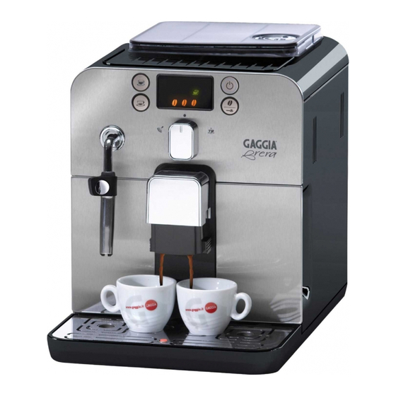
Page 6: External Machine Parts
GAGGIA 01 INTRODUCTION 1.6.1 External machine parts Grinder adjustment knob Cup stacking surface Control panel Dispensing spout compartment Cup holder grill Full drip tray indicator Service door Brew group Wand protective gripper Hot water/steam wand ON-OFF power button Drip tray... -
Page 7: Internal Machine Parts
GAGGIA 01 INTRODUCTION 1.6.2 Internal machine parts Coffee grinder Side door microswitch boiler Coffee grinder motor Pump Temperature sensor Card - PWR/CPU Turbine Rev. 00 OCTOBER 2009 Page / 04... -
Page 8: Technical Specifications
CHAPTER 2 TECHNICAL SPECIFICATIONS Rev. 00 OCTOBER 2009... -
Page 9: Machine Parameters And Performance
GAGGIA 02 TECHNICAL SPECIFICATIONS 2.1. Technical specifications Power supply and output: 240 V~ 50 Hz 1400 W - 230 V~ 50/60 Hz 1400 W - 120 V~ 60 Hz 1500 W - 100 V~ 50/60 Hz 1300 W Temperature monitoring:... - Page 10 GAGGIA 02 TECHNICAL SPECIFICATIONS RINSE Initial rinse Final rinse When performed When the machine is When the machine is switched switched on and the boiler off electronically, manually or temperature is ≤ 50°C automatically after 60’ , after having dispensed at least one coffee, before switching off No.
-
Page 11: Brief Instructions
CHAPTER 3 BRIEF INSTRUCTIONS Rev. 00 OCTOBER 2009... -
Page 12: Customer And Programming Menu
GAGGIA 03 BRIEF INSTRUCTIONS 3.1. Customer and programming menu Indications Causes Solutions Machine at correct temperature - for coffee bean dispensing Proceed with the dispensing process - for hot water dispensing Steady on Machine at correct temperature - for ground coffee dispensing... - Page 13 GAGGIA 03 BRIEF INSTRUCTIONS Indications Causes Solutions Machine in rinsing phase - wait for the machine to complete Wait until end of procedure the procedure Cyclic blinking The appliance requires a Perform the descaling cycle descaling cycle To enter the descaling cycle press the...
-
Page 14: Operation, Cleaning And Maintenance
GAGGIA 03 BRIEF INSTRUCTIONS 3.2. Operation, cleaning and maintenance Operating the machine Fill water tank Fill the coffee bean hop- Switch on the appliance Fill the circuit Place a container under the steam wand and turn the selector to the ”... -
Page 15: Operating Logic
CHAPTER 4 OPERATING LOGIC Rev. 00 OCTOBER 2009... -
Page 16: Water Circuit
GAGGIA 04 OPERATING LOGIC 4.1. Water circuit HOT WATER/STEAM • Traditional water system • Turbine - Amount of coffee dispensed into the cup • Reciprocating piston type pump (13 - 15 bar) • Compensation valve (opening pressure 16 - 18 bar) •... -
Page 17: Control Ringnut And Valve
GAGGIA 04 OPERATING LOGIC 4.2. Control ringnut and valve DESCRIPTION Mushroom valve cap Spring for mushroom valve Mushroom valve support Mushroom valve Sealing OR When dispensing coffee the mushroom valve opens at 4 bar +/- 0.5 Manual opening when dispensing water... -
Page 18: Coffee Cycle Operating Diagram
GAGGIA 04 OPERATING LOGIC 4.3. Coffee cycle operating diagram Main START STOP switch ON Time Coffee grinder Pulses (Dosage) Heating approx. 45 sec. Pump Pump activity (turbine pulses) depending on the product quantity selected Gearmotor Brew group Heating Ready Coffee cycle... -
Page 19: Single Microswitch
GAGGIA 04 OPERATING LOGIC 4.4. Single microswitch The gearmotor is powered by a direct current motor that engages with the smaller double toothed wheel using a worm screw. The brewing unit is mounted on the axle of the large gear wheel and when a coffee is... -
Page 20: Coffee Grinder Operation
GAGGIA 04 OPERATING LOGIC 4.6. Coffee grinder operation Ceramic coffee grinder The coffee grinder is driven by a direct current motor (1) using a worm screw helicoidal wheel transmission (2). The worm screw (2) drives a plastic gear wheel (3), which turns the lower grinder (4) and the increment pin (5). -
Page 21: Dose Self-Learning
GAGGIA 04 OPERATING LOGIC Dose self-learning With an algorithm based on three pieces of information (listed below) detected by the machine computer, the average dose is adjusted automatically (SELF-LEARNING). Number of coffee grinder pulses taking place during the grinding cycle Max. -
Page 22: Service Mode
CHAPTER 5 SERVICE MODE Rev. 00 OCTOBER 2009... -
Page 23: Test Mode
GAGGIA 05 SERVICE MODE 5.1. Test mode To enter Test Mode 1. place the control knob in the water position 2. keep the espresso coffee key pressed 3. switch the appliance on from the 0/I button located at the rear of it; the icons scroll through in sequence 4. - Page 24 GAGGIA 05 SERVICE MODE Brew group operational check PRESS NOTES Illumination of icon SETTINGS Steady on Steady on When absorption is greater than 300 mA with the group inserted and 200 Group in work position (up) Group in standby position mA with the group not inserted.
-
Page 25: Servicing & Maintenance
CHAPTER 6 SERVICING AND MAINTENANCE Rev. 00 OCTOBER 2009... -
Page 26: Repair Schedule
GAGGIA 06 SERVICING AND MAINTENANCE 6.1. Repair schedule Action Visual inspection (transport damage) Machine data check (rating plate) Operational check / problem analysis Opening machine Visual inspection Operational tests Repairing the faults encountered Checking any modifications (view info, new sw, etc.) -
Page 27: Final Test
GAGGIA 06 SERVICING AND MAINTENANCE 6.3. Final test Support/ Test Procedure Standard Tolerance tool 2-3 Espressos for Measuring Espresso Same amount adjustment purposes scoop 2-3 Coffees for Measuring Coffee Same amount adjustment purposes scoop Noise Standard The cream should Amount of... -
Page 28: Disassembly
CHAPTER 7 DISASSEMBLY Rev. 00 OCTOBER 2009... -
Page 29: Outer Elements Disassembly
GAGGIA 07 DISASSEMBLY 7.1. Outer elements disassembly 1) Remove the dreg drawer, water tank, coffee bean hopper cover, drip tray, brew group, steam wand cap and pannarello (frother) 2) Unscrew the screws shown and remove the finger protection device and coffee bean hopper... -
Page 30: Keypad Card And Valve Card Disassembly
GAGGIA 07 DISASSEMBLY 7.3. Keypad card and valve card disassembly 1) Unscrew the screws shown 2) Release the stop device and the flat cable Slide out the front panel 3) Disconnect the connector shown and unscrew the CPU card support... -
Page 31: Power/Cpu Card Disassembly
GAGGIA 07 DISASSEMBLY 7.4. Power/CPU card disassembly 1) Unscrew the screw shown and re- move the card protection 2) Slide out the card, removing all con- nections 7.5. Gearmotor disassembly 1) Unscrew the screws holding the boiler pin in place, remove them and unscrew the other screws... -
Page 32: Boiler Disassembly
GAGGIA 07 DISASSEMBLY 7.6. Boiler disassembly 1) Remove the coffee grinder sound insulating cover 2) Remove the boiler insulation 3) Unscrew the screws shown. 4) Unscrew the screw and remove the plastic support. Disconnect the hoses and the connections 7.7. -
Page 33: Pump And Turbine Disassembly
GAGGIA 07 DISASSEMBLY 6) Unscrew the screws shown to remove the insert on the base of the casing 7) Unscrew the screws shown and disconnect the valve from the water connections. 7) Unscrew the screws shown and disconnect the valve from the mesh hoses 7.8. - Page 34 GAGGIA 07 DISASSEMBLY 7.9. Disassembling and fitting OETIKER clamps 1) Boiler connection 2) Other connections Replacing the hoses 1) Use a suitable pair of pliers to remove the clamp (as illustrated) 2) Tighten the clamp as illustrated Rev. 00 OCTOBER 2009...
-
Page 35: Coffee Grinder Disassembly
GAGGIA 07 DISASSEMBLY 7.10. Coffee grinder disassembly 1) To remove the coffee grinder, simply slide it out and remove its connections 2) When replacing it, make sure the spring (A) and the coffee pipe (B) are positioned correctly Rev. 00 OCTOBER 2009... -
Page 36: Grinder Adjustment / Assembly And Disassembly
GAGGIA 07 DISASSEMBLY 7.11. Grinder adjustment / assembly and disassembly 1) To remove the upper grinder support, using a hex key push down and turn clockwise to release the grinder support from the bayonet coupling 2) To remove the grinder blade from the upper... -
Page 37: Rev. 00 October
CHAPTER 8 NOTES Rev. 00 OCTOBER 2009... - Page 38 GAGGIA 08 NOTES Rev. 00 OCTOBER 2009 Page / 01...
- Page 39 CHAPTER 9 WATER CIRCUIT DIAGRAM Rev. 00 OCTOBER 2009...
-
Page 40: 9.1. Water Circuit Diagram
GAGGIA 09 WATER CIRCUIT DIAGRAM 9.1. Water circuit diagram Rev. 00 OCTOBER 2009 Page / 01... - Page 41 CHAPTER 10 ELECTRICAL DIAGRAM Rev. 00 OCTOBER 2009...
-
Page 42: 10.1 Wiring Diagram
GAGGIA 10 WATER CIRCUIT DIAGRAM 10.1 Wiring diagram Rev. 00 OCTOBER 2009 Page / 01...
Need help?
Do you have a question about the Brera and is the answer not in the manual?
Questions and answers