Table of Contents
Advertisement
SPECIFICATION
Wingspan :
Length
Weight
Radio
Servo
Electric motor: BL 2826/06 OUTRUNER
Battery:
Speed control: 45A
Propeller :
Instruction Manual book
1,450mm
:
1,140 mm
:
3.3kg
: 05 channels.
: 07 mini servos+ 3servos Retracts (FUTABA S3170G)
4S-LIPO -14.8V - 5.000 mAh
12 x 8
57.09 in.
44.88 in.
7.26 Lbs.
ITEM CODE:BH 142
Made in Vietnam.
Advertisement
Table of Contents

Subscribe to Our Youtube Channel
Related Manuals for Black Horse Model BEDE BD-5


Summary of Contents for Black Horse Model BEDE BD-5
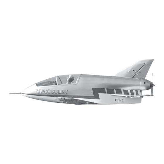
- Page 1 Instruction Manual book ITEM CODE:BH 142 SPECIFICATION Wingspan : 1,450mm 57.09 in. Length 1,140 mm 44.88 in. Weight 3.3kg 7.26 Lbs. Radio : 05 channels.
- Page 2 BEDE BD-5 Instruction Manual Item code: BH142 This instruction manual is designed to help you build a great flying aeroplane. Please read this BEDE BD-5. manual thoroughly before starting assembly of your Use the parts listing below to identify all parts.
-
Page 3: Safety Precaution
BEDE BD-5 Instruction Manual Item code: BH142 Caution: this model is not a toy! If you are a beginner to this type of powered model, please ask an experienced model flyer for help and support. If you attempt to operate the model without knowing what you are doing you could easily injure yourself or somebody else. - Page 4 BEDE BD-5 Instruction Manual Item code: BH142 REPLACEMENT LARGE PARTS D. Rudder. A . Fuselage. E. Carbon tube wing dihedral brace. B. Wing panel(B1,B2). F. Carbon tube Horizontal stabilizer. H.Cowling C.Horizontal stabilizer(C1,C2). G.Decal sheet K.Pilot C3.Elevator REPLACEMENT SMALL PARTS 1.Retract main gear.
-
Page 5: Installing The Aileron Servos
BEDE BD-5 Instruction Manual Item code: BH142 Temporary pin to keep hinge centered. Assemble then apply drops of thin I. AILERON. C/A to center of hinge,on both sides. 1.INSTALLING THE AILERON SERVOS. 1) Install the rubber grommets and brass eyelets onto the aileron servos. - Page 6 BEDE BD-5 Instruction Manual Item code: BH142 5. Instal servo tray with aileron servo into the wing as same as picture below. 2x10mm. Secure. Secure. Repeat the procedure for the other wing half. 3) Using the thread as a guide and using...
-
Page 7: Installing The Aileron Linkages
BEDE BD-5 Instruction Manual Item code: BH142 II. FLAP 1.INSTALLING THE FLAP SERVO Aileron control horn Repeat the procedure for the other wing half. INSTALLING THE AILERON LINKAGES. Installing the aileron linkages as pictures below. Flap. Bottom side 35mm. 2x10mm. - Page 8 BEDE BD-5 Instruction Manual Item code: BH142 2.INSTALLING THE FLAP CONTROL HORN. Install flap control horn as same as picture below. Control horn Flap. Bottom side. A+B Epoxy PLUS glue Repeat the procedure for the other wing half. Top side.
- Page 9 BEDE BD-5 Instruction Manual Item code: BH142 INSTALLING RETRACTABLE LANDING GEAR. PARTS REQUIRED 3x15mm. 5x30mm. Retract servo Retract servo. Retract servo. Bottom side.
- Page 10 BEDE BD-5 Instruction Manual Item code: BH142 3x15mm. Secure. Secure. Secure. 5x30mm.
- Page 11 BEDE BD-5 Instruction Manual Item code: BH142 Plastic parts for Retract servos. Top side. INSTALLING THE RETRACT PUSHROD. See pictures below: C/A glue. secure. Bottom side. Flap Bottom side...
- Page 12 BEDE BD-5 Instruction Manual Item code: BH142 INSTALLING ELECTRIC MOTOR. See pictures below: R e t r a c t pushrod. 2x10mm. 3x15mm. Secure. Top side Secure. Bottom side Left side. Repeat the procedure for the other gear.
- Page 13 BEDE BD-5 Instruction Manual Item code: BH142 COWLING Drill a hole 3mm diameter. 1) Slide the fiberglass cowl over the engine and line up the back edge of the cowl with the marks you made on the fuselage. Left side.
-
Page 14: Horizontal Stabilizer
BEDE BD-5 Instruction Manual Item code: BH142 Front view. Secure. Elevator servo HORIZONTAL STABILIZER. Horizontal stabilizer installation See picture below. INSTALLING THE ELEVATOR SERVOS. 1. Install the rubber grommets and brass collets into the elevator servo. Test fit the servo into the servo tray. -
Page 15: Elevator Control Horn Installation
BEDE BD-5 Instruction Manual Item code: BH142 Bottom side Bottom side Cut the covering away from the slot. Temporary pin to keep hinge centered. ELEVATOR CONTROL HORN INSTALLATION. Elevator control horn install as same as the way of aileron control horn. Please see pic- tures below. -
Page 16: Elevator Pushrod Installation
BEDE BD-5 Instruction Manual Item code: BH142 Plastic parts top side of pushrod. Cut. Elevator control horn ELEVATOR PUSHROD INSTALLATION. Elevator pushrod install as same as the way of aileron pushrod. C/A glue. M2 lock nut. Bottom side E l e v a t o r... -
Page 17: Rudder Installation
BEDE BD-5 Instruction Manual Item code: BH142 RUDDER INSTALLATION. See picture below: bend 90 degree. Cut the covering away from the slot. Temporary pin to keep hinge centered. Cut. Assemble then apply drops of thin C/A to center of hinge,on both sides. -
Page 18: Rudder Servo Installation
BEDE BD-5 Instruction Manual Item code: BH142 Top side. RUDDER SERVO INSTALLATION. Rudder servo install as same as method of elevator servo. 2x10mm. See pictures below: Rudder servo S e c u r e . servo tray RUDDER CONTROL HORN INSTALLA- TION. -
Page 19: Rudder Pushrod Installation
BEDE BD-5 Instruction Manual Item code: BH142 Control horn Rudder. INSTALLING RETRACT SERVO NOSE GEAR. RUDDER PUSHROD INSTALLATION. See picture below: Rudder pushrod install as same as the way of aileron pushrod. Retract servo nose gear 30mm. Retract servo... - Page 20 BEDE BD-5 Instruction Manual Item code: BH142 INSTALLING RETRACT NOSE GEAR. See picture below: 5x30mm Secure. 3x 15mm Secure.
- Page 21 BEDE BD-5 Instruction Manual Item code: BH142 wire cable. INSTALLING SERVO NOSE GEAR. See picture below: Servo nose gear Secure. Servo nose gear wire cable.
-
Page 22: Wing Attachment
BEDE BD-5 Instruction Manual Item code: BH142 Plywood of nose gear. Battery Receiver C/A glue. WING ATTACHMENT. 1.Locate the carbon tube wing dihedral brace. 12 mm INSTALLING THE RECEIVER AND BATTERY-ESC. 485mm. 1. Plug the servo leads and the switch lead into the receiver. -
Page 23: Installing Cockpit Fuselage
BEDE BD-5 Instruction Manual Item code: BH142 Left wing. Bottom side. Right wing. INSTALLING COCKPIT FUSELAGE . See picture below: 3.Insert two wing panels as pictures below. - Page 24 BEDE BD-5 Instruction Manual Item code: BH142 Top side. A +B Epoxy PLUS glue Installing antenna See picture below: C/A glue. Top side. Top side.
-
Page 25: Control Throws
BEDE BD-5 Instruction Manual Item code: BH142 CONTROL THROWS. BALANCING. 1) It is critical that your airplane be bal- 1) We highly recommend setting up a anced correctly. Improper balance will cause plane using the control throws listed.
Need help?
Do you have a question about the BEDE BD-5 and is the answer not in the manual?
Questions and answers