Table of Contents
Advertisement
Quick Links
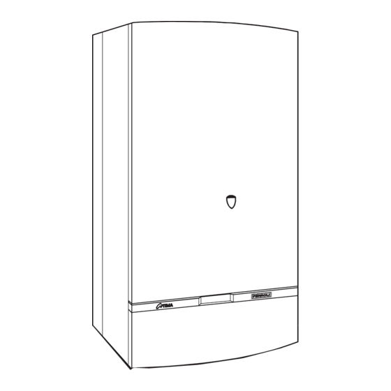
GAS CONDENSING COMBINATION BOILER
Phone numbers:
Installer
Service Engineer
Serial No.
G.C. NO: 47-367-21
Stockton Close, Minworth Industrial Park, Minworth, Sutton Coldfield, West Midlands B76 8DH
WALL MOUNTED, ROOM SEALED,
FAN ASSISTED,
ALL SPECIFICATIONS SUBJECT TO CHANGE
Sales: 0121/3523500 - Fax 0121/3523510
2001
INSTALLATION
INSTRUCTIONS
Read these Instructions thoroughly
before using the appliance
FERROLI HELPLINE
FOR SERVICE INFORMATION OR
HELP TELEPHONE: 0121 352 3500
ALWAYS QUOTE YOUR SERIAL NUMBER
FOR IMMEDIATE ASSISTANCE
VMF7
Advertisement
Table of Contents

Related Manuals for Ferroli optima 2001 VMF7


Summary of Contents for Ferroli optima 2001 VMF7
- Page 1 WALL MOUNTED, ROOM SEALED, FAN ASSISTED, GAS CONDENSING COMBINATION BOILER INSTALLATION INSTRUCTIONS Read these Instructions thoroughly before using the appliance FERROLI HELPLINE Phone numbers: FOR SERVICE INFORMATION OR HELP TELEPHONE: 0121 352 3500 Installer ALWAYS QUOTE YOUR SERIAL NUMBER FOR IMMEDIATE ASSISTANCE Service Engineer Serial No.
- Page 2 2001 page INDEX Burner pressure C.H. and D.H.W. General Description Gas pressure adjustment with Honeywell Related Documents VR 4605 NA 4003 valve Technical Data 8.7 D.H.W. Burner Pressure Appliance Dimensions 9. System operation Boiler Flow Diagram 10. Handing Over to the User Key of boiler flow diagram General Wiring Diagram Installation Details...
-
Page 3: General Description
At the factory the central heating output is pre-set to maximum. The appliance is not suitable for external installation. This appliance can also be installed using the Ferroli two pipe flue system providing flue lengths up to 20 m (see flue options instructions). -
Page 4: Technical Data
2001 Technical data NATURAL GAS (G20) Nominal heat input 26.6 kW (gross caloric value) Nominal heat output 22.6 kW Nominal heat output condensing (30-50°C) 24.2 kW Minimum heat input (gross caloric value) 11.9 kW Minimum heat output 9.7 kW Minimum heat output condensing (30-50°C) 10.7 kW Gas rate 2.53 m... -
Page 5: Appliance Dimensions
2001 Appliance Dimensions FRONT VIEW LEFT SIDE VIEW REAR VIEW 97.5 77.5 1. Electricity cable entry 2. Gas supply 3. Domestic Hot Water outlet Fig. 1 4. Domestic Cold Water inlet 5. Central Heating Pressure relief valve TOP VIEW 6. Central Heating Flow outlet 7. - Page 6 2001 Boiler Flow Diagram Fig. 2...
- Page 7 2001 50. Central heating limit thermostat 1. Fixing point 51. Central heating frost thermostat 5. Room sealed compartment 53. Heat exchanger venting point 7. Gas inlet 56. Expansion vessel 8. Domestic hot water outlet 58. Fan air outlet pressure test point 9.
-
Page 8: Installation Details
2001 Installation Details Gas Safety (Installation & Use) Regulations: 1994 In the interest of safety, it is the law that all gas appliances are installed by a competent person in accordance with the above Regulations, Building Regulations/Building Standards Scotland, Codes of Practice, current I.E.E. Regulations and the byelaws of the Local Water Undertaking. -
Page 9: Air Supply
2001 Terminal Position Air supply APPLIANCE FLUE SYSTEM ROOM-SEALED AIR VENT AREAS APPLIANCE LOCATION IN ROOM AIR VENT HIGH LEVEL: 238 cm (37 in. IN COMPARTMENT OPEN TO ROOM LOW LEVEL: 238 cm (37 in. AIR VENT HIGH LEVEL: 119 cm (18 in. -
Page 10: Water System
2001 Flue system The boiler allows the flue outlet to be taken from the rear of the boiler or from either side. A standard flue length of 0.75 metres is provided. Alternative lengths of two or three metres can be supplied (equivalent to wall thicknesses of up to 565, 1815 and 2815 mm for rear flues and deduct 91 mm plus distance from side wall for side outlet flues). - Page 11 2001 Cold water Additional expansion vessel C.H. (if required) Filling point C.H. Bypass Fig. 6 NOTE: A bypass must be fitted as far as possible from the boiler if thermostatic radiator valves are fitted throughout. TEMPORARY FILLING LOOP A temporary filling loop of the above type conforming to WRC approval should be installed between the cold water mains and the central heating system.
- Page 12 2001 Built-in Central Heating Water Circulating Pump The pump head available for circulating the water is given in fig. 8. N.B. - The pump is factory set at position 3. The pump is a Grundfos type 15-50 UPS series. Grunfos Pump performance graph Note - Minimum flow through boiler heat exchanger at any time should not fall below 6 litres per minute.
- Page 13 2001 Installation Note - To mount the boiler on the wall, a two person lift will be needed. UNPACKING The appliance is delivered in 2 cartons. The large carton contains the boiler, and the Installation/Servicing and Users Instructions. The second carton contains the mounting jig assembly, complete with isolating valves, the assembly fixing screws and wall plugs (x4), the boiler mounting nuts and washers (x2), drilling template, flue assembly and turret.
- Page 14 2001 Important Note - Always use two spanners to prevent twisting of soft copper pipework on the boiler. Flush out the water system. Note - The maximum inlet cold water pressure must not exceed 10 bar (145 P.S.I.) and a water governor or a pressure reducing valve will be required if the pressure is in excess of 5 bar (72 P.S.I.).
- Page 15 2001 PREPARING THE FLUE ASSEMBLY Rear Flue Outlet (fig. 12) Important - The aluminium flue pipe must protrude into the outside grill by 2 in (50 mm), never cut it to the same length as the plastic air pipe (aluminium flue pipe = plastic air inlet pipe + 50 mm !). Aluminium flue pipe length = Plastic air inlet pipe length plus 50 mm (2") longer.
- Page 16 2001 CONNECTING THE BOILER Place the boiler on its back. Remove the boiler base plate, four screws (fig. 16). Remove the plugs fitted to the boiler water connections. Remove the bag of sealing washers from the boiler pipework. Remove the front panel by gripping on both sides, slide up to disengage lugs and pull away.
- Page 17 2001 Fixing points Fig. 15 Lift here Fixing screws Fig. 16 Fig. 17...
- Page 18 2001 FITTING THE FLUE ASSEMBLY With Sufficient Clearance To Insert Assembly From Inside 6.1.1 Push the air duct seal onto the air duct at the cut end. 6.1.2 Insert the flue assembly into the wall ensuring a 2° slope back to the boiler. 6.1.3 Make good internal wall face.
- Page 19 2001 External compensation sensor (optional) 7.3.1 To be wired to terminals 7 and 8 on the appliance connector box (see fig. 18), low voltage twin wire can used. 7.3.2 External sensor location The external sensor should be installed on the North, North-West wall or on the one facing the majority of the main living rooms in the building.
- Page 20 2001 Setting of compensation curve The boiler can now be regulated to ensure the design critia of the system is matched to the outside tempera- ture 7.4.1 Consult the outside compensation graph provided (fig. 19c) 7.4.2 Following the bottom ouside temperature line to find the outside temperature. The system is designed for. 7.4.3 Trace a line vertically until you reach the designed system flow temperature.
- Page 21 2001 COMMISSIONING AND TESTING Filling the Central Heating System Burner pressure Automatic air vent Vent cap test point Heat exchanger vent Pump Pressure gauge C.H. pressure relief valve Gas inlet pressure test point D.H.W. drain point Fig. 20 Remove the top front panel by gripping both sides, slide up to disengage lugs and pull away. Loosen the cap of the automatic air vent (fig.
- Page 22 2001 Flame viewing opening Outside compensation adjustment screw C.H. pressure gauge C.H. boiler thermostat AUTO AUTO 12: 31 OVERRI DE Flame failure reset knob Condensate hose Time clock C.H./D.H.W. selector switch Domestic hot water thermostat Fault diagnostic lights fig. 21 To Light the Boiler (fig.
- Page 23 2001 Burner Pressure C.H. and D.H.W. To Range Rate the Boiler C.H. (not required for standard installations). The boiler can be range rated for an output from 9.7 kW (33,000 btu/h) up to 22.6 kW (77,000 Btu/h). When the boiler is supplied it is factory set at the maximum output 22.6 kW (77,000 Btu/h).
- Page 24 2001 Honeywell VR 4605 NA 4003 valve with V7335A4014 Modureg Gas pressure Adjustment With the burner lit: Connect suitable pressure gauge to burner test point "B", and then: Disconnect air pressure compensation tube "H"; Disconnect the wires from coil "C" of the Modureg; Remove protective cover "D";...
- Page 25 3.5 mbar +/- 0.5 mbar. If the burner pressure is not as stated check the inlet working pressure (fig. 22) which should be minimum 20 mbar. If that is correct, consult Ferroli. No attempt should be made to alter D.H.W. burner pressure.
-
Page 26: Wiring Diagram
2001 Wiring diagram 16 Fan 230V 11 10 9 8 7 6 5 4 3 2 1 32 Central heating pump 50Hz 34 C.H. flow temperature sensor 42 D.H.W. temperatuure sensor 43 Air pressure switch 47 Modulating regulator (MODUREG) gas valve 49 Overheat cut-off thermostat 50 Heat exchan. - Page 27 2001 General Notes - For use on the 2001 fitted with VMF7 Printed Circuit Board *The central heating pump (32) will run to disperse heat if the temperature at the heat exchanger limit thermostat (50) is too high *The frost thermostat (51) will switch on the boiler for central heating if the temperature is too low. °...
-
Page 28: Replacement Of Parts
2001 General fault finding Engineer Please Check 1. Gas available (check kitchen and gascocks) 2. Electrical mains is on. 3. Water pressure Central Heating System (min. 1 bar on pressure gauge) 4. Water flow domestic hot water (min. 0.5 Gal/min - 2.5 L/min.) (fills a 1 pint milk bottle max. 15 seconds). 5. - Page 29 2001 Base Plate Remove the four fixing screws (fig. 16). Side Panels For each panel, remove two fixing screws at base of appliance and single fixing screw at top of appliance (fig. 30). Also remove hinged control panel cover. Note - The panels are located in keyhole slots, push panels upwards and pull away. Removal of Combustion Chamber Outer Cover Remove the five combustion chamber outer cover fixing screws and undo four buckle clips (fig.
- Page 30 2001 Details Combustion Chamber 16. Fan 28. Flue collector from heat exchanger Fig. 32...
- Page 31 2001 Details Burner 81. Ignition electrode 82. Flame sensing electrode Fig. 33 FLOWMETER (Domestic Hot Water) AND FILTER Refer to section 1, items a, b, c, d, f and g (drain D.H.W. only fig. 34). Undo the flow switch unions and carefully lower the flow switch taking care not to lose either the (three) sealing washers, filter or flow restrictor.
- Page 32 2001 HONEYWELL GAS VALVE (fig. 31) Refer to Section 1, items a, c, d, f, g, h (left hand side panel) and j. Disconnect the four electrical connections from the top of the valve. Disconnect modulating balance tube by removing the fixing screw, and gently pull off from the front of the valve. Disconnect the gas supply to the gas valve at the inlet union.
- Page 33 2001 D.H.W. TEMPERATURE SENSOR OR CENTRAL HEATING TEMPERATURE SENSOR Refer to section 1, items a, b, c, d, f, g, h (left hand side panel) and k. Identify the sensor from fig. 2. Disconnect the electrical connections to the sensor. Unscrew the temperature sensor.
-
Page 34: Time Clock
2001 10.0 PRESSURE GAUGE Refer to Section 1, items a, b, (central heating), c, d, f, g and j. Remove the shim then the temperature sensing phial from its pocket (fig. 37). Unscrew the pressure sensor from its housing (fig. 37). (Access from below). Unscrew the knurled nut from the rear of the gauge, and remove the gauge forwards. - Page 35 2001 To Set Own ON and OFF times. Symbol in Display = ON time 1. Slide switch (A) to right position (P) 1.1 Use buttons + and - to set 1st ON time eg. 6:00 6:00 6:30 Display Display 2. Press button (P) 2.1 Use buttons + and - to set OFF time, eg.
- Page 36 2001 13.0 REMOVAL OF FAULT DIAGNOSTIC/TEMPERATURE CONTROL Refer to Section 1, items a, c, d, f, and j. Remove P.C.B. top cover by unscrewing the two fixing screws. Pull control box front cover forward Disconnect electrical connections from fault diagnostic control panel Remove rataining nuts from the C.H.
- Page 37 2001 15.0 REMOVAL AND RE-PRESSURISING OF C.H. EXPANSION VESSEL Note - If there is less than 500 mm clearance above the boiler or if the boiler has a rear flue outlet then removal of the expansion vessel can only be achieved by first removing the boiler from the wall. Note - For rear exit flues it is not recommended that the flue and air duct be removed from the wall.
- Page 38 2001 Exploded view gas line, combustion chamber and draft diverter Fig. 49 Complete combustion chamber Burner Venturi Combustion chamber insulation back panel Injector Combustion chamber insulation side panel 104 pressure test point Flue collector 105 Gas valve 108 Inlet tube gas valve Panel isolation 111 Ignition electrode Combustion chamber panel...
- Page 39 2001 Exploded view heat exchanger + C.H. and D.H.W. parts Fig. 50 130 Copper heat exchanger for C.H. + D.H.W. 131 Central heating frost thermostat 132 Central heating limit thermostat 148 Flue deflector 133 Overheat cut-off thermostat 149 Temperature sensor 140 Automatic air vent 151 Cold water inlet filter 141 Safety valve...
-
Page 40: Spare Parts List
2001 Spare Parts List Item No. G.C. Part No. Makers Part No No. Off DESCRIPTION 386816 800130 C.H. safety valve 803510 803710 Main injector (Natural Gas) 803690 Central heating pump 386818 800310 Temperature sensor 394246 801160 Automatic air vent 386829 801220 Cold water flow limiter 10 l/min. -
Page 41: Domestic Hot Water Performance
2001 Domestic Hot Water Performance Fig. 1 - D.H.W. Pressure Drop VS. flow A = Standard with cold water Flow Restricter B = Cold Water Flow Restricter Removed Fig. 1 Fig. 2 - D.H.W. temperature VS. flow A = Cold Water 15°C B = Cold Water 5°C litres/min Fig. - Page 42 2001 Special Installation Possibilities: Two-pipe air intake/flue outlet Special Air Intake/Flue Outlet The standard Flue/air intake hood on top of the boiler can be replaced by a special two pipe flue adapter. For details see separate instructions; «Optional flue systems» top view boiler...
- Page 43 2001...
- Page 44 Phone numbers: Installer Service Engineer BECAUSE OF OUR CONSTANT ENDEAVOUR FOR IMPROVEMENT DETAILS MAY VARY SLIGHTLY FROM THOSE QUOTED IN THESE INSTRUCTIONS. ALL SPECIFICATIONS SUBJECT TO CHANGE Stockton Close, Minworth Industrial Park, Minworth, Sutton Coldfield, West Midlands B76 8DH Tel.: 0121/3523500 - Fax 0121/3523510...
Need help?
Do you have a question about the optima 2001 VMF7 and is the answer not in the manual?
Questions and answers