
Related Manuals for Miller ICE-27T


Summary of Contents for Miller ICE-27T
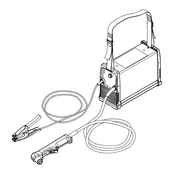
- Page 1 OM-225 216E 2006−10 Processes Air Plasma Cutting and Gouging Description Air Plasma Cutter Spectrum 375 X-TREME And ICE-27T Torch File: Plasma Cutters Visit our website at www.MillerWelds.com...
- Page 2 We know you don’t have time to do it any other way. That’s why when Niels Miller first started building arc welders in 1929, he made sure his products offered long-lasting value and superior quality.
-
Page 3: Table Of Contents
TABLE OF CONTENTS SECTION 1 − SAFETY PRECAUTIONS - READ BEFORE USING ........1-1. -
Page 5: Section 1 − Safety Precautions - Read Before Using
SECTION 1 − SAFETY PRECAUTIONS - READ BEFORE USING pom _4/05 Y Warning: Protect yourself and others from injury — read and follow these precautions. 1-1. Symbol Usage Means Warning! Watch Out! There are possible hazards with this procedure! The possible hazards are shown in the adjoining symbols. - Page 6 If ventilation is poor, wear an approved air-supplied respirator. EXPLODING PARTS can injure. Read and understand the Material Safety Data Sheets (MSDSs) and the manufacturer’s instruction for metals to be cut, coatings, D On inverter power sources, failed parts can ex- and cleaners.
-
Page 7: Additional Symbols For Installation, Operation, And Maintenance
D Use proper static-proof bags and boxes to store, move, or ship PC boards. D Read Owner’s Manual before using or servic- ing unit. D Use only genuine Miller/Hobart replacement H.F. RADIATION can cause interference. parts. D High frequency (H.F.) can interfere with radio FLYING METAL can injure eyes. -
Page 8: Principal Safety Standards
1-5. Principal Safety Standards Safety in Welding, Cutting, and Allied Processes, ANSI Standard Z49.1, Code for Safety in Welding and Cutting, CSA Standard W117.2, from from Global Engineering Documents (phone: 1-877-413-5184, website: Canadian Standards Association, Standards Sales, 178 Rexdale Bou- www.global.ihs.com). -
Page 9: Section 2 − Consignes De Sécurité − Lire Avant Utilisation
SECTION 2 − CONSIGNES DE SÉCURITÉ − LIRE AVANT UTILISATION pom_fre 4/05 Y Avertissement : se protéger et protéger les autres contre le risque de blessure — lire et respecter ces consignes. 2-1. Signification des symboles Signifie Mise en garde ! Soyez vigilant ! Cette procédure présente des risques de danger ! Ceux-ci sont identifiés par des symboles adjacents aux directives. - Page 10 N’approchez pas le tube du chalumeau et l’arc pilote lorsque la gâ- LE BRUIT peut endommager l’ouïe. chette est enfoncée. Le câble de masse doit être pincé correctement sur la pièce à cou- Certaines applications de coupage produisent un bruit per, métal contre métal (et non de telle sorte qu’il puisse se constant, ce qui peut endommager l’ouïe si le niveau détacher), ou sur la table de travail le plus près possible de la ligne...
-
Page 11: Dangers Supplémentaires En Relation Avec L'installation, Le Fonctionnement Et La Maintenance
D Les bouteilles ne doivent pas être près de la zone de coupage ni de D Détournez votre visage du détendeur−régulateur lorsque vous ouvrez tout autre circuit électrique. la soupape de la bouteille. D Un contact électrique ne doit jamais se produire entre un chalumeau D Le couvercle du détendeur doit toujours être en place, sauf lorsque de plasma d’arc et une bouteille. -
Page 12: Principales Normes De Sécurité
D Veiller à couper à une distance de 100 mètres de tout équipement LE COUPAGE Ã L’ARC peut causer électronique sensible. des interférence. D S’assurer que la source de coupage est correctement branchée et mise à la terre. D L’énergie électromagnétique peut gêner le fonction- D Si l’interférence persiste, l’utilisateur doit prendre des mesures sup- nement d’appareils électroniques comme des ordi- plémentaires comme écarter la machine, utiliser des câbles blindés... -
Page 13: Section 3 − Definitions
SECTION 3 − DEFINITIONS 3-1. Symbols And Definitions Low Air Pressure Amperes Increase Power Light Light Loose Shield Cup Temperature Light Light SECTION 4 − INSTALLATION 4-1. Specifications Amperes Input Rated at Rated Cutting Cutting Output Output, Plasma Plasma Input 60 Hz, Capacity Gas Flow/... -
Page 14: Duty Cycle And Overheating
4-3. Duty Cycle And Overheating For Units Connected to a 120 Volt Circuit Duty Cycle is percentage of 10 min- or a 240 Volt Circuit: utes that unit can cut at rated load without overheating. 35% Duty Cycle At 27 amperes, 92 volts dc If unit overheats, thermostat(s) opens, output stops, Temperature trouble light goes On, and cooling... -
Page 15: Connecting Gas/Air Supply
4-6. Connecting Gas/Air Supply Use only clean, dry air with 90 to 110 psi (620 to 758 kPa) pressure. Gas/Air Inlet Opening Hose Teflon Tape Obtain hose with 1/4 NPT right- hand thread fitting. Wrap threads with teflon tape (optional) or apply pipe sealant, and install fitting in opening. -
Page 16: Electrical Service Guide For 240 Vac
4-8. Electrical Service Guide For 240 VAC CAUTION: INCORRECT INPUT POWER can damage this welding power source. This welding power source requires a CONTINUOUS supply of 60 Hz (+10%) power at +10% of rated input voltage. Phase to ground voltage shall not exceed +10% of rated input voltage. Do not use a generator with automatic idle device (that idles engine when no load is sensed) to supply input power to this welding power source. -
Page 17: Connecting 1-Phase Input Power For 240 Vac
4-10. Connecting 1-Phase Input Power For 240 VAC Y Installation must meet National and Local Codes − have only qualified persons make this installation. Y Disconnect and lockout/tagout =GND/PE Earth Ground input power before connecting input conductors from unit. Y Always connect green or green/ yellow conductor supply... -
Page 18: Connecting Input Power
4-11. Connecting Input Power Y Do Not cut off power cord connector and rewire. The power cord connector and plugs will work with standard NEMA receptacles. Modifying power cord, connector, and plugs will void product warranty. 18 in (460 mm) Serial Number/Rating Label located on bottom of base;... -
Page 19: Section 5 − Operation
SECTION 5 − OPERATION 5-1. Controls 225 175-B Output Control with 120 VAC input power, and the overload power (see Section 4-1). protection on the input power circuit fre- Use control to set cutting output. Power Light quently opens, either reduce the cutting out- If 22-27 amperes of cutting output is used put and/or the cut time or find more adequate Trouble Lights (See Section 6-6) -
Page 20: Cutting Speed
5-2. Cutting Speed Recommended Cut Speeds At 27 Amperes Output Thickness Recommended Cut Speeds* Inches mm/min 16 ga 4,775 Mild Steel 3/16 1,016 12.7 *Recommended Cut Speed is approximately 80% of maximum. Aluminum and Stainless Steel cut speeds at these thicknesses may be reduced as much as 20%. Recommended Cut Speeds At 20 Amperes Output Thickness Recommended Cut Speeds*... -
Page 21: Sequence Of Operation
5-4. Sequence Of Operation For maximum cutting speed and tip life in non-shielded applications, EXAMPLE Of Cutting Operation use a standoff distance of 1/8 in (3.2 mm). Dragging tip will reduce tip life for non-shielded applications. For maximum cutting speed and tip life in shielded applications, place the drag shield directly on the workpiece. -
Page 22: Section 6 − Maintenance & Troubleshooting
SECTION 6 − MAINTENANCE & TROUBLESHOOTING 6-1. Routine Maintenance Maintain more often Y Disconnect power before maintaining. during severe conditions. n = Check Z = Change ~ = Clean l = Replace Reference * To be done by Factory Authorized Service Agent Each Section 4-5, n Gas/Air Pressure... -
Page 23: Wrapper Removal
6-3. Wrapper Removal Y Turn power, disconnect input power plug from receptacle before working on unit. Y Significant DC voltage can remain on capacitors after unit is Off. Wait until all front panel LED’s are off before removing wrapper. Y Check voltage according to Section 6-4 after removing wrapper. -
Page 24: Dc Bus Voltage Check
6-4. DC Bus Voltage Check Y Turn Off welding power Y 440 Volts DC can be present on the capacitor bus source, disconnect and significant DC voltage can remain on input power. capacitors after unit is Off. Always check the Y Significant DC voltage can voltage on inverter assembly as shown to be sure the input capacitors have discharged before... -
Page 25: Checking Or Replacing Filter Element
6-5. Checking Or Replacing Filter Element Y Check voltage according to Section 6-4, and be sure voltage is near zero before touching any parts. Turn power Off, and disconnect input power plug from receptacle. Remove wrapper from unit (see Section 6-3). Filter Base Filter Filter Cup... -
Page 26: Overload Protection: Trouble Lights & Checking Shield Cup Shutdown System
6-6. Overload Protection: Trouble Lights & Checking Shield Cup Shutdown System Power Light Light is steady if input power is okay. Light flashes for the following conditions: If input power is 120 volts ac, but power supply is less than 92 volts ac. If input power is 240 volts ac, but power supply is greater than 276 volts ac. -
Page 27: Checking/Replacing Retaining Cup, Tip, And Electrode
6-7. Checking/Replacing Retaining Cup, Tip, And Electrode Overtightening will strip threads. Do not overtighten retaining cup during assembly. Do not cross-thread parts causing stripping. Use care during torch assembly and parts replacement. Inspect shield cup, tip, and electrode for wear before cutting or whenever cutting speed has been significantly reduced. -
Page 28: Torch And Work Cable Connections
6-8. Torch And Work Cable Connections Y Check voltage according to Section 6-4, and be sure voltage is near zero before touching any parts. If torch or work cable needs to be removed or replaced, proceed as follows: Turn power Off, and disconnect input power plug from receptacle. - Page 29 Notes OM-225 216 Page 25...
-
Page 30: Section 7 − Electrical Diagram
SECTION 7 − ELECTRICAL DIAGRAM Figure 7-1. Circuit Diagram OM-225 216 Page 26... - Page 31 224 682-B OM-225 216 Page 27...
-
Page 32: Section 8 − Parts List
SECTION 8 − PARTS LIST Hardware is common and not available unless listed. 804 507-B Figure 8-1. Main Assembly OM-225 216 Page 28... - Page 33 Item Dia. Part Mkgs. Description Quantity Figure 8-1. Main Assembly ... . +225180 CABLE,POWER 10 FT 2 IN 14GA 3C W/MVP ......
- Page 34 (1) 190 220 Spring, trigger assembly 169 231 Grease, silicone (1) 225 615 Torch, replacement 12 ft (1) See Figure 8-3 for additional consumable parts. Figure 8-2. Torch, ICE-27T Retaining O−Ring Swirl 169 232 Electrode Ring 202 808 176 656...
- Page 35 Effective January 1, 2006 (Equipment with a serial number preface of “LG” or newer) This limited warranty supersedes all previous Miller warranties and is exclusive with no other Warranty Questions? guarantees or warranties expressed or implied. LIMITED WARRANTY − Subject to the terms and conditions...
-
Page 36: Options And Accessories
Contact the Delivering Carrier to: File a claim for loss or damage during shipment. For assistance in filing or settling claims, contact your distributor and/or equipment manufacturer’s Transportation Department. © PRINTED IN USA 2006 Miller Electric Mfg. Co. 2006−01...
Need help?
Do you have a question about the ICE-27T and is the answer not in the manual?
Questions and answers