Sign In
Upload
Download
Table of Contents
Contents
Add to my manuals
Delete from my manuals
Share
URL of this page:
HTML Link:
Bookmark this page
Add
Manual will be automatically added to "My Manuals"
Print this page
×
Bookmark added
×
Added to my manuals
Manuals
Brands
Miller Manuals
Flashlight
XT30C
Manual
Miller XT30C Manual
Hide thumbs
Also See for XT30C
:
Owner's manual
(40 pages)
1
2
Table Of Contents
3
4
5
6
7
8
9
10
11
12
13
14
15
16
17
18
19
20
21
22
23
24
25
26
27
28
29
30
31
32
33
34
35
36
37
38
39
40
page
of
40
Go
/
40
Contents
Table of Contents
Troubleshooting
Bookmarks
Table of Contents
Table of Contents
Section 1 − Safety Precautions - Read before Using
Symbol Usage
Plasma Arc Cutting Hazards
Additional Symbols for Installation, Operation, and Maintenance
California Proposition 65 Warnings
Principal Safety Standards
EMF Information
Section 2 − Consignes de Sécurité − Lire Avant Utilisation
Signification des Symboles
Dangers Liés Au Coupage À L'arc Au Plasma
Dangers Supplémentaires en Relation Avec L'installation, Le Fonctionnement Et la Maintenance
Proposition Californienne 65 Avertissements
Principales Normes de Sécurité
Informations Relatives Aux CEM
Section 3 − Specifications
XT30 Specifications
XT30 Torch Dimensions
XT30C Specifications
XT30C Torch Dimensions
XT40 Torch Specifications
XT40 Torch Dimensions
XT60 Torch Specifications
XT60 Torch Dimensions
Section 4 − Installation
Installing 30 Ampere (XT30) Torch and Work Cable on Spectrum 375 X-TREME
(Stock No. 907 529), and Using Trigger Safety Lock
Installing 30 Ampere (XT30) Torch and Work Cable on Spectrum 375 X-TREME (Stock No. 907 303 and 907 339) Prior to Serial No. MB290336P, and Using Trigger Safety Lock
Installing 30 Ampere (XT30C) Torch and Work Cable on Spectrum 375 (Stock No. 907532), and Using Trigger Safety Lock
Installing 30 Ampere (XT30C) Torch and Work Cable on Spectrum 375 (Stock No. 903 891), and Using Trigger Safety Lock
Installing 40 Ampere (XT40) Torch and Work Cable on Spectrum 625 X-TREME
(Stock No. 907 404 and 907 531), and Using Trigger Safety Lock
Connecting and Disconnecting 40 Ampere (XT40) Torch on Spectrum 625 X-TREME
(Stock No. 907 579), and Using Trigger Safety Lock
Connecting and Disconnecting Work Cable on Spectrum 625 X-TREME
(Stock No. 907 579)
Connecting and Disconnecting 60 Ampere (XT60) Torch on Spectrum 875 and Spectrum 875 Auto-Line, and Using Trigger Safety Lock
Section 5 − Operation
Plasma Cutting System Practices
Sequence of Cutting Operation
Sequence of Piercing Operation
Section 6 − Maintenance & Troubleshooting
Routine Maintenance
Shield Cup Shutdown System
Checking/Replacing Retaining Cup, Tip, and Electrode
Troubleshooting
Section 7 − Parts List
Advertisement
Quick Links
1
Xt60 Torch Specifications
2
Section 7 − Parts List
Download this manual
Visit our website at
www.MillerWelds.com
XT Torches
OM-254 449B
2014−02
Processes
Air Plasma Cutting
and Gouging
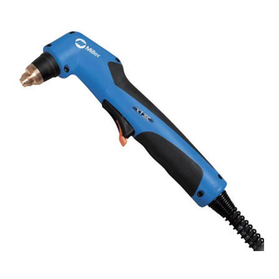
Description
Plasma Cutting Torch
File: Plasma Cutters
Table of
Contents
Previous
Page
Next
Page
1
2
3
4
5
Advertisement
Table of Contents
Troubleshooting
SECTION 6 − MAINTENANCE & TROUBLESHOOTING
28
Troubleshooting
30
Need help?
Do you have a question about the XT30C and is the answer not in the manual?
Ask a question
Questions and answers
Related Manuals for Miller XT30C
Welding System Miller Spectrum 375 Owner's Manual
(40 pages)
Welding System Miller Spectrum 625 X-TREME Owner's Manual
Air plasma cutter (52 pages)
Flashlight Miller XT60 Manual
(40 pages)
Flashlight Miller SMITH EQUIPMENT HANDI-HEET Owner's Manual
Acetylene/atmospheric air torch systems (24 pages)
Flashlight Miller WP Series Owner's Manual
(20 pages)
Flashlight Miller W-250(WP-20) Owner's Manual
W-250 / wp-20 series hand-held water-cooled tig (gtaw) torch (25 pages)
Flashlight Miller ICE-12C Owner's Manual
Air-cooled torches for plasma arc cutting (38 pages)
Flashlight Miller W-400 Owner's Manual
(24 pages)
Flashlight Miller OBT-600 Owner's Manual
Torches for automated applications (16 pages)
Flashlight Miller ICE-50 Owner's Manual
Air-cooled arc plasma cutting torches (28 pages)
Flashlight Miller MC-80 Owner's Manual
(20 pages)
This manual is also suitable for:
Xt40
Xt60
Table of Contents
Print
Rename the bookmark
Delete bookmark?
Delete from my manuals?
Login
Sign In
OR
Sign in with Facebook
Sign in with Google
Upload manual
Upload from disk
Upload from URL


Need help?
Do you have a question about the XT30C and is the answer not in the manual?
Questions and answers