Table of Contents
Advertisement
Quick Links
Advertisement
Table of Contents

Related Manuals for Quality Craft M870P-28ADC


Summary of Contents for Quality Craft M870P-28ADC
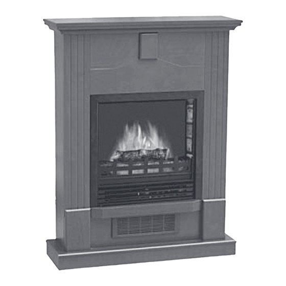
- Page 1 ELECTRIC FIREPLACE HEATER I N S T R U C T I O N M A N U A L M870P-28ADC NDF-65NB-1 ATTENTION: 1. Find a location for the fireplace heater that is protected from direct sunlight. 2. Do not plug the unit into the power outlet before you...
-
Page 2: Important Safety Instructions
S A F E T Y I N S T R U C T I O N S IMPORTANT SAFETY INSTRUCTIONS WHEN USING ELECTRICAL APPLIANCES, BASIC PRECAU- TIONS SHOULD ALWAYS BE FOLLOWED TO REDUCE THE RISK OF FIRE, ELECTRIC SHOCK, AND INJURY TO PERSONS, INCLUDING THE FOLLOWING: IMPORTANT Please note: when you open the carton... - Page 3 S A F E T Y I N S T R U C T I O N S and similar indoor locations. Never locate 15) Avoid the use of an extension cord be- heater where it may fall into a bathtub or cause the extension cord may overheat and other water container.
- Page 4 S A F E T Y I N S T R U C T I O N S at C is available for connecting three-blade grounding-type plugs to two-slot recep- tacles. The green grounding plug extending from the adapter must be connected to a permanent ground such as a properly grounded outlet box.
-
Page 5: Parts List
A S S E M B LY I N S T R U C T I O N S PARTS LIST: Fireplace insert A) Top panel B) Base panel C) Front upper panel D) Left front upper panel E) Right front upper panel F) Left front lower panel G) Right front lower panel H) Left upper side panel... - Page 6 A S S E M B LY I N S T R U C T I O N S PANEL D together with 1 KD SCREW. Attach PLASTIC CONNECTOR until the PANELS/KD PANEL G and PANEL E together with 1 KD SCREWS can be installed.
- Page 7 A S S E M B LY I N S T R U C T I O N S Step 5: Attach the FRONT UPPER PANEL Step 8: Attach 2 MOUNTING FEET to (C ) to the LEFT AND RIGHT FRONT UPPER fireplace insert (one on each side) with 8 PANEL (D and E) with 2 KD SCREWS (1 MOUNTING FEET SCREWS (R) (4 screws in...
-
Page 8: Operation
O P E R A T I O N 2. Position the back edge of the mantle close to the wall. 3. Attach the SAFETY CABLE to the mantle using the SCREW FOR MANTLE. 4. Use the SCREW FOR WALL to attach the other end of SAFETY CABLE to the wall. -
Page 9: Maintenance
M A I N T E N A N C E This temperature control dial can only be used while the ON/OFF switch and 750W & 1500W switches are in the ON position. DIMMER CONTROL KNOB: Turn the dimmer dial clockwise or counter clockwise to get the desired flame intensity. - Page 10 R E P A I R S E T REPLACING THE FLAME TOUCH UP REPAIR PAINT EFFECT LIGHT AND LOG-SET Paint directly on the mantel unit if LIGHT BULBS necessary. Fig. A. Step 1: Remove 4 screws on the back of fireplace and remove the rear cover of the unit.
- Page 11 R E P A I R S E T fig. B fig. E 2. Drill the holes with diameter 3/4 inches (10 mm) and depth 3/4 inches (10 mm) on the mantel. Each PLASTIC CONNECTOR OPTION 2: needs 3 holes. See Fig. C. Use the SMALL L-BRACKETS and SCREWS.
-
Page 12: Warranty
SCREWS as shown in Fig. H. unit. This warranty is void if in the opinion of Quality Craft the unit has been tampered with, altered, misused, damaged, abused or used with the wrong power source. Light CLEANING bulbs are not covered by this warranty.
Need help?
Do you have a question about the M870P-28ADC and is the answer not in the manual?
Questions and answers