
Subscribe to Our Youtube Channel
Related Manuals for INNO VIEW 5


Summary of Contents for INNO VIEW 5
- Page 1 View 5 ARC Fusion Splicer User Manual Please read this manual before operating your fusion splicer, and keep it for future reference. 2014/11 Rev.0.1...
- Page 2 View 5 User Manual...
-
Page 4: Table Of Contents
Contents Introduction Chapter 1: Technical specifications Applicable fiber type Splice loss Splice mode Heat oven Power supply Dimensions and weight Environment Other Battery precautions Chapter 2: Installation Safety warnings and precautions Operational safety warnings Maintenance and external care precautions Transport and storage precautions Installation Unpacking the splicer Splicer overview... - Page 5 Touch screen On/Off Fiber zoom function on screen Preparing the fibers How to make a splice Placing the fibers Inspecting the fibers Splicing How to protect the splice Heating procedure Chapter 4: Splice Programs Displaying the active splice program Selecting a splice program General splicing steps Pre-fusion Fusion...
- Page 6 Operation procedure Dust check Operation procedure Motor calibration Operation procedure Arc calibration Operation procedure Electrode setting Update software Chapter 8: Other Functions & Utilities Data storage Display splice record Delete splice record Cancel data storage System setting Monitor position Power save option System information Appendix I: Reasons for high splice loss and solutions Appendix II: List of error messages...
- Page 7 Important: INNO Instrument strongly recommends all users to read this manual before operating VIEW 5. This manual is valid for the following software version:...
-
Page 8: Introduction
The simple-but-trendy product design, sophisticated internal structure and reliable durability make the splicer be suitable for any operating environment. Dynamic operation interface and automatic splice mode provide users great convenience. For more information of VIEW 5, please visit our official website at www.innoinstrument.com... -
Page 9: Chapter 1: Technical Specifications
Heat oven 5 applicable protection sleeve: 20mm, 30mm, 40mm, 50mm, 60mm • Heating time: 8- 900s • Cooling time: 0-180s • Typical heating time: 13s • Heat mode: Various heat modes available • Heat oven: VIEW 5 special heat oven •... -
Page 10: Power Supply
Power supply Standard AC power voltage: AC 100-240V, 50-60Hz • Standard DC power voltage: DC 9-14V • Dimensions and weight Size: Height x Width x Depth = 147mm x 130mm x 155mm • Weight: 2.21kg (battery included) • Environment Operating condition: 0~5000m above sea level, 0~95% relative humidity, •... -
Page 11: Battery Precautions
Battery precautions DO NOT collide the battery with sharp or hard objects. • DO NOT transport or store the battery with metals simultaneously. • DO NOT throw, drop, impact or bend the battery. • DO NOT strike the battery with hammers or tread on it. •... -
Page 12: Chapter 2: Installation
VIEW 5 at any time. Any behaviors that do not follow the warnings and cautions will break the safety standard about design, manufacture, and usage of the fusion splicer. -
Page 13: Maintenance And External Care Precautions
Please use VIEW 5 designed charger only. Do not place any heavy objects on • the AC power cord. Keep the power cord away from heat source. Using an improper cord or a damaged cord may cause fuming, electric shock or equipment damage and may even result in fire, injury or death. -
Page 14: Transport And Storage Precautions
Transport and storage precautions When the splicer is moved from cold to warm environment, you should allow the • splicer to warm up gradually. Otherwise, the condensation generated inside will bring harmful effects to the splicer. Pack the fusion splicer well for long time storage. •... -
Page 15: Installation
Important: Please follow the instructions below carefully. Unpacking the splicer Hold the handle upwards, then lift the splicer out of the carrying case. Package ① VIEW 5 ⑪ Stripper ② High Precision Cleaver ③ Fiber Holder ④ AC Adapter ⑤ Cooling Tray ⑥... - Page 16 Documents (not shown) User manual • Supplier’s declaration of conformity • Test protocol • Equipped with VFH-40 fiber holder (Standard package) Chapter 2 Installation...
-
Page 17: Splicer Overview
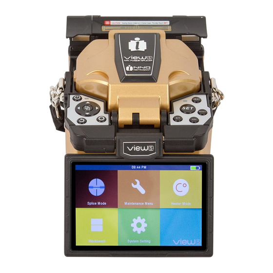
Splicer overview Loop Heat oven On / Off button Control buttons Power supply / Battery Display USB 2.0 MINI USB Power supply connector Chapter 2 Installation... -
Page 18: Power Supply
Power supply Battery Switch off the splicer. Press the [Release] button at the side of the splicer and take out the battery from the splicer. Insert Release button Take out the battery Insert the battery into the power unit dock until it clicks into place. Charge the battery Connect the battery charger to the battery. -
Page 19: How To Check Remaining Battery Capacity
Note: Check and make sure the remaining battery capacity is 20% or greater before splicing. If the battery capacity is less than 20%, please use AC / DC adapter to power the splicer. Heat will be generated during the charging process. -
Page 20: Chapter 3: Basic Operation
Basic Operation Turning on the splicer Press [Power] key on the operation panel, and wait the splicer to be turned on and move to Workbench page. Adjusting the monitor position Users can adjust the monitor position by moving it with a desired angle in purpose of operation convenience. -
Page 21: Adjusting The Monitor Brightness
Adjusting the monitor brightness In the initial interface, press “◀” or “▶” to adjust the monitor brightness until a clear image can be seen. Note: The LCD monitor is a precise component produced by manufacturing factory under strict quality control. However, some tiny dots in different colors may still remain on the screen. -
Page 22: Fiber Zoom Function On Screen
Step 3: Cleave the fiber In order to ensure the best splicing result, cleave the fibers with high precision cleaver such as INNO Instrument VF series fiber cleaver, and strictly control the cleaving lengths shown as below. Note: Remember to slip a heat-shrink sleeve onto either end of the fibers at the beginning of each fiber preparation. -
Page 23: How To Make A Splice
Make sure that the bare fiber and its cleaved section are clean. Important: Avoid putting the fibers on a dusty working surface. • Avoid swaying the fibers in the air. • Check if the V-grooves are clean. If not, must clean it with pure alcohol-soaked •... -
Page 24: Splicing
Large cleave Dust on fiber Chip angle Note: The fibers are checked automatically when you press “Set” button. The splicer automatically focuses the fibers and checks for damage or dust particles. Splicing Select any appropriate splice mode. • Start splicing by pressing [SET] button. •... - Page 25 Open the heat oven lid Move into the heat oven clamp Splicing position Heating LED indicator [HEAT] button Chapter 3 Basic Operation...
-
Page 26: Chapter 4: Splice Programs
Splice Programs VIEW 5 has an intuitive and simple but very powerful program structure to operate. Splice programs define arc currents, splice times as well as various parameters used when performing a splice. Therefore, it is essential to select the correct splice program. -
Page 27: Selecting A Splice Program
Selecting a splice program Select [Splice mode] from the main menu. Select [Splice mode] and select [Select splice mode]. Select an appropriate splice mode Selected splice mode appears on the screen. Press [RESET] button to return to initial interface page. Chapter 4 Splice Programs... -
Page 28: General Splicing Steps
General splicing steps This section explains the steps involved in automatic splicing process and describes how various program parameters are related to this process. The normal splicing process can be divided into two sections; pre-fusion and fusion. Pre-fusion During pre-fusion, the splicer performs automatic alignment and focusing, where the fibers are subjected to a low pre-fuse current for cleaning purposes;... -
Page 29: Splice Program Parameters Under General Splicing Process
Splice program parameters under general splicing process Parameter Description A list of splice modes stored in the splicer database. Upon inputting the Template appropriate mode, the selected splice mode stored in database area is copied to a user-programmable area. Name Title for a splice mode expressed in up to seven characters. - Page 30 Set the overlap amount of fibers at the fiber propelling stage. Relatively Overlap small [Overlap] is recommended if [Preheat Arc Value] is low, while relatively large [Overlap] is recommended if [Preheat Arc Value] is high. A cleaning arc burns out micro dust on the surface of the fiber with an arc Clean Arc Time discharge for a short period of time.
-
Page 31: Chapter 5: Splice Option
Splice Option Setting up splice mode Select [Splice option] in menu. • Select a parameter to be changed. • Parameter Description If “Auto Start” is set to “On”, splicing starts automatically as soon as the Auto Start windproof cover is closed. Fibers should be prepared and placed into the splicer in advance. - Page 32 Loss Setting to “OFF” ignores the faults and continues to complete the splicing even if the message “Loss Error”, “Cleave Shape Error”, “Fat Error”, or “Thin Error” appears. Thin Fiber Image On Screen Gap Set Pause1 Align Set the displaying method of the fiber image on the screen during splicing operation.
-
Page 33: Chapter 6: Heater Mode
For each type of protection sleeve, VIEW 5 has its optimum heating mode. These modes can be found in the database area for reference. Copy the appropriate mode and paste it to the user–programmable area. -
Page 34: Editing Heater Mode
Select heat mode. Selected heat mode appears on the screen. Press [RESET] button to return to initial interface. Editing heat mode Heating conditions stored in heater mode can be edited or changed. Select [Edit Heat Mode] in [Heater mode] menu. Select the mode to be edited. -
Page 35: Deleting Heater Mode
Select the parameters to be edited. Deleting heat mode Select [Heater Mode] menu. • Select [Delete Heat Mode]. • Select the heat mode to be deleted. • Note: The gray modes (20mm, 30mm) are the system preset initial heat modes which cannot be deleted. -
Page 36: Chapter 7: Maintenance Menu
Maintenance Menu The splicer has a function to perform routine maintenance. This chapter describes how to use the maintenance menu. Press □ button, and select [Maintenance menu]. • Select a function to perform. • Replace electrodes As electrodes are worn out during the splicing process, oxide generated on the tips of electrodes should be regularly eliminated. -
Page 37: Stabilize Electrodes
• the electrodes position. Diagnostic test VIEW 5 has a built-in diagnostic test function that allows the user to evaluate several critical variable parameters with only one simple step. Perform this function in case of splicer operation fault. Operation procedure Select [Diagnostic Test] in [Maintenance Menu]. -
Page 38: Dust Check
Execute [Diagnostic test], then the following checks will be made. • Parameter Description LED Calibration Measure and adjust the brightness of LED. Dust Check Check the optical path for dust or dirt and judges whether they disturb fiber observation. If contamination exists, press the return button twice to display the location. -
Page 39: Operation Procedure
Arc calibration Atmospheric conditions such as temperature, humidity and pressure are constantly changing, which creates variability in the arc temperature. VIEW 5 is equipped with temperature and pressure sensors that are used in a constant feedback monitoring control system to maintain the arc power at a stable level. -
Page 40: Electrode Setting
“Operation Complete” is displayed. Electrode setting Set the electrode change warnings. INNO Instrument recommends replacing the electrodes every 3500 discharge to ensure the best splice results. Select [Electrode Setting] in [Maintenance Menu]. -
Page 41: Chapter 8: Other Functions & Utilities
Other Functions & Utilities Data storage This splicer stores up to 2000 splicing results. Contents of data stored are different depending on the splicing mode. Display splice record Splicing results stored in the splicer can be displayed. Select [Display Splice Record] in [Data Storage] menu. •... -
Page 42: System Setting
System setting Parameter Description Buzzer Set On/Off of the buzzer. Temperature Unit Set the unit of temperature. Automatic Heating If “Automatic heating” is set to “ON”, heat oven will perform heating automatically when the fiber is put into the heat oven. Language Select a language to be displayed on the screen. -
Page 43: Monitor Position
Monitor Position The direction of the splicer display before shipping from the factory is set to “Front”, but users can change it to “Rear”. When [Monitor position] is changed, the direction of the arrow keys is reversed. Changing monitor position Select [Monitor Position] in [System Setting] menu. -
Page 44: Power Save Option
Power save option This function is important for power conservation. If the power saving function is not set during battery use, the number of splice cycles will be reduced. Insert a power unit, and turn on the splicer. • Select [Power Save Option] in [System Setting] menu. •... -
Page 45: Appendix I: Reasons For High Splice Loss And Solutions
Appendix I Reasons for high splice loss and solutions Symptom Name Reason Solution Dust on V-groove or fiber Clean V-groove and fiber Core Axial Offset holder. holder. Dust on V-groove or fiber Clean V-groove and fiber holder. holder. Core Angle Error Bad fiber end-face quality. - Page 46 Arc power is not adequate. Perform [Arc Calibration]. Adjust [Preheat Arc Value], Thin Some arc parameters are [Preheat Arc Time], not adequate. or increase [Overlap]. Adjust [Preheat Arc Value], Some arc parameters are Line [Preheat Arc Time], not adequate. or [Overlap]. Note: A vertical line sometimes appears at the splice point when MM fibers or dissimilar fibers (different diameters) are spliced.
-
Page 47: Appendix Ii: List Of Error Messages
Appendix II List of error messages During the splice operating process, if the error messages are shown on the screen, please follow the solution precisely as shown in the list below. If it is not possible to solve the problem, the splicer may require service by a qualified service center. - Page 48 Dust on the fiber surface. Re-prepare the fiber. AUTO mode is not applicable in Different fiber types on two sides. this case; select a suitable splice Unknown Fiber Type mode to redo splicing. AUTO mode can only detect The fiber is a non-standard fiber. standard SM, MM, NZ fibers.
- Page 49 Re-prepare the fibers. Too large axial offset (>4.0㎛). Fiber Axis Align Failed The motor is not calibrated. Perform [Motor calibration]. Dust or dirt on the fiber surface. Prepare the fiber again. Perform [Dust check] after The lenses are covered with dust. cleaning the lenses.
-
Page 50: Appendix Iii: Frequent Questions And Troubleshooting
Appendix III Frequent questions and troubleshooting Note: The solutions of common faults for reference are as follows. Please con- tact sales agents for further support if needed. Power does not turn off when pressing ON/OFF button. • Press and hold the key until the LED blinks, and then release the button to turn •... - Page 51 AUTO mode is only applicable for SM, MM, NZ fibers. AUTO mode may not be • able to identify while splicing special fibers. Mismatch between estimated splice loss and actual splice loss. • The estimated loss is just an estimated number by calculation, for reference •...
- Page 52 Korea Head Office China Branch Office USA Branch Office Please visit us on Facebook www.facebook.com/innoinstrument www.innoinstrument.com Copyright 2014 INNO Instrument Inc. All rights reserved. ⓒ 11, Sunhwan-ro 214beon-gil, Jungwon-gu, Seongnam-si, Gyeonggido 462-807, Republic of Korea 82-31-742-8755 82-31-742-8799 Printed in Korea...
Need help?
Do you have a question about the VIEW 5 and is the answer not in the manual?
Questions and answers