Table of Contents
Advertisement
Quick Links
Advertisement
Table of Contents

Subscribe to Our Youtube Channel
Related Manuals for INNO VIEW 5 Pro


Summary of Contents for INNO VIEW 5 Pro
- Page 1 User Manual New friendly GUI design SOC Support Screen Zoom Remote Control VIEW 5 Pro MONITORING WEB SERVICE CORE-ALIGNMENT FUSION SPLICER Please read this manual before operating your fusion splicer, and keep it for future reference. Ver V1.02...
-
Page 2: Table Of Contents
VIEW 5 Pro Content Preface Chapter 1 Technical Parameters 1.1 Applicable Fiber Type............................1.2 Splice Loss................................1.3 Splice Mode................................1.4 Heat Oven................................1.5 Power Supply............................... 1.6 Size and Weight..............................1.7 Environmental Conditions..........................1.8 Others................................... 1.9 Battery precautions............................. Chapter 2 Installation 2.1 Safety Warning and Precautions........................ - Page 3 7.2 Replace Electrodes..........................7.3 Stabilize Electrodes..........................7.4 Motor Calibration........................... 7.5 Dust Check.............................. 7.6 Electrode Setting............................ 7.7 Update Software............................ Chapter 8 Other Functions & Utilities 8.1 Data Storage............................8.2 Menu Lock............................... 8.2 System Setting............................8.3 Time Lock..............................8.3.1 Time Lock setting..........................8.3.2 Remark..............................
-
Page 4: Preface
VIEW 5 Pro Preface Thank you for choosing VIEW 5 Pro Arc Fusion Splicer from INNO Instrument. VIEW 5 Pro adopts innovative product design and exquisite manufacturing technology so as to deliver unprecedented splicing experience to customers. The totally new technology greatly reduces splicing and heating time, and advanced estimation method and alignment technique ensure the accuracy of splice loss estimation. -
Page 5: Chapter 1 Technical Parameters
13 sec (45mm, slim 60mm), 15 sec(60mm). * Heating mode: Various in-built heat modes available. * Heater: Specific heater for VIEW 5 Pro fusion splicer. 1.5 Power Supply * Standard AC power voltage: AC 100 to 240V, 50 to 60Hz;... -
Page 6: Others
VIEW 5 Pro 1.8 Other * Observation and display: Two cameras, 5-inch color LCD display, Full touch screen. * 320x magnification for single X or Y view, or 520x magnification for double click X or Y view.. * Pull test:1.96 to 2.25N. -
Page 7: Chapter 2 Installation
⑨ Please use VIEW 5 Pro specific charger only. Do not place any heavy objects on the AC power cord. Keep the power cord away from heat source. Using an improper cord or a damaged cord may cause fuming, electric shock or equipment damage and may even result in fire, injury or death. -
Page 8: Installation
VIEW 5 Pro Transport and Storage Precautions ① When the splicer is moved from cold to warm environment, you should allow the splicer to warm up gradually. Otherwise, the condensation generated inside will bring harmful effects to the splicer. ② Pack the fusion splicer well for long time storage. -
Page 9: Overview Of External Parts
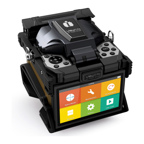
2.3 Overview of External Parts Heat oven ON/OFF button Control buttons Display Battery USB TYPE-C Power Supply Connector... -
Page 10: Power Supply Method
VIEW 5 Pro 2.4 Power Supply Method Battery Following is the way of installing a battery. Shut off fusion splicer. Press on release button at lateral,drawing the battery out of the fusion splicer. Place the battery into power unit slot until you push it into the right place. -
Page 11: Chapter 3 Basic Operation
2. Clean bare fibers with pure alcohol-soaked gauze or lint-free tissue. 3. Cleave the fiber In order to ensure the best splicing result, cleave the fbers with high precision cleaver such as INNO Instrument V series fiber cleaver, and strictly control the cleaving lengths shown as below. -
Page 12: How To Make A Splice
VIEW 5 Pro 3.3 How to Make a Splice Put the optical fiber in ① Open the safety shield. ② Raise the fiber clamps. ③ Position the fibers into V-grooves. Make sure the fiber ends are between the V-groove edges and the electrode tip. -
Page 13: How To Protect The Splice
3.4 How to Protect the Splice After splicing, put the fiber with heat-shrink sleeve into the heat oven. Press [Heat] button to execute heat-shrink process to strengthen the splice point. Heating Procedure ① Open the heat oven lid ② Lift the left and right fiber holders on the splicer. Hold the heat-shrink sleeve (previously placed onto the fiber). Lift the spliced fibers and hold them taut. - Page 14 VIEW 5 Pro Splicing position Open the heat oven lid move into heat oven clamp [HEAT] Button Heating LED indicator...
-
Page 15: Chapter 4 Splice Mode
Chapter 4 - Splice Mode A2 has an intuitive and simple but very powerful program structure to operate. Splice programs define arc currents, splice times as well as various parameters used when performing a splice. Therefore, it is essential to select the correct splice program. -
Page 16: General Splicing Steps
VIEW 5 Pro 4.3 General Splicing Steps This section explains the steps involved in automatic splicing process and describes how various program parameters are related to this process. The normal splicing process can be divided into two sections: pre-fusion and fusion. -
Page 17: Parameters For Normal Splicing Process
4.4 Parameters for Normal Splicing Process Parameter Description A list of splice modes stored in the splicer database is displayed. Upon inputting the appro- Template priate mode, the selected splice mode stored in database area is copied to a selected splice mode in user-programmable area. -
Page 18: Chapter 5 Splice Option
VIEW 5 Pro Chapter 5 - Splice Option 5.1 Splice Mode Setting 1 Select [Splice option] in menu. 2 Select a parameter to be changed. Parameter Description If “Auto start” is set to ON, splicing starts automatically as soon as the wind protector is Auto start closed. -
Page 19: Chapter 6 Heater Mode
Select a heating mode that best matches with the protection sleeve used. For each type of protection sleeve, VIEW 5 Pro has its optimum heating mode. These modes can be found in the database area for reference. Copy the appropriate mode and paste it to the user–programmable area. Users can edit those parameters. -
Page 20: Delete Heat Mode
VIEW 5 Pro ② Select the parameters to be edited. 6.3 Delete Heat Mode ① Select [Heater Mode] menu. ② Select [Delete Heat Mode]. ③ Select the heat mode to be deleted ⚠ Note: The gray modes (20mm, 30mm) are the system preset initial heat modes which cannot be deleted... -
Page 21: Chapter 7 Maintenance Menu
② Select a function to perform. 7.1 Maintenance VIEW 5 Pro has a built-in diagnostic test function that allows the user to evaluate several critical variable parameters with only one simple step. Perform this function in case of splicer operation fault. -
Page 22: Stabilize Electrodes
Do not pull out wiring when replacing electrode. Do not exceed the normal finger strength when tightening screw. ⑤ INNO Instrument strongly recommends all users to do stabilizing electrodes and arc calibration after electrodes replacing to keep good splice results and splice strength (Details are described below). -
Page 23: Dust Check
7.5 Dust Check Through image acquisition, the splicer detects dust and contaminants on the splicer, camera, and objective lenses that may result in improper splicing. This function checks the optical path for the presence or absence of contaminants, and judges whether they will affect the quality of fiber splicing. Operation Procedure ①... -
Page 24: Chapter 8 Other Functions & Utilities
VIEW 5 Pro Chapter 8 - Other Functions & Utilities 8.1 Data Storage This splicer stores up to 10,000 splicing results. Contents of data stored are different depending on splicing mode. Display Splice Record Splicing results stored in the memory can be displayed with image. Enter [Splice Mode] - > [Data Storage] Menu and Select [Display Splice Record] to view. -
Page 25: System Setting
8.3 Time Lock 8.3.1 Time Lock setting ① Enter [main menu] - [System Setting] - [System Setting] - [Time Lock] ② Enter device password ③ Available to set up to 6 dates [YY/MM/DD] for Time Lock ④ Press “R” button to reset the date ⑤... -
Page 26: System Information
VIEW 5 Pro Power Save Option This function is important for power conservation. If the power saving function is not set during battery pack use, the number of splice cycles will decrease. (1) Insert a power unit and turn on the splicer. -
Page 27: Chapter 9 View Pro Manager
Chapter 9 - VIEW PRO MANAGER 9.1 Preparation * Load battery and turn on the device. * Detach the SIM card Tray from under the USB cover of the splicer * Insert Nano SIM card to slot on the right side of machine. Mini-SIM Micro-SIM Nano-SIM... -
Page 28: Access To View Pro Manager Website
VIEW 5 Pro * Networks status can be observed on workbench interface * Check Network and GPS activation icon on workbench (GPS signal is activated at open area) ICON Description GPS is activated GPS is not activated Network is activated... -
Page 29: Register The Device
9.5 Register the Device 1) Go to“Device” menu 2) Click “Add” button 3) Enter the Serial Number 4) Enter the IMEI Number 5) Click button 6) Select Device Group 7) Select Your Authority 8) Click “Change” 9) Click “Bind Splice” *... -
Page 30: Feature Of View Pro Manager
VIEW 5 Pro 9.6 Feature of VIEW PRO MANAGER 9.6.1 Monitor 9.6.2 Record... - Page 31 · More Introduction and guidance can be found in “HELP” under account menu. (Under developing)
- Page 32 VIEW 5 Pro Appendix I High Splice loss: Cause and remedy Symptom Name Cause Remedy Fiber core axial There’ s dust in V-grooves and fiber Clean the V-grooves and fiber hammer offset hammer Fiber core angle There’ s dust in V-grooves and fiber...
- Page 33 Appendix II Error Message List An error message may appear on the screen when using a splicer, the solution precisely as shown in the list below. If it is not possible to eliminate the problem, maybe some faults occur in the fusion splicer. Consult your sales agency. Error Message Cause Solution...
- Page 34 VIEW 5 Pro Prepare the fiber (stripping, Axial offset (>0.4um) cleaning, and cleaving) again. Fiber Axis Align Failed The motor is not calibrated Do the “Motor Calibration” maintenance. There’ s dust or dirt on the fiber Prepare the fiber (stripping, surface cleaning, and cleaving) again.
- Page 35 Appendix III The following gives the solution of some of the common problems for reference. If you cannot solve the problems, please contact the manufacturer directly. 1. Power does not turn off when press “ON/OFF” button. ★ Press and hold the key “ON/OFF” until the LED flashes, release the button, and the splicer will be turned off. 2.
- Page 36 The End * Products models and specifications are subject to change without prior notice.
- Page 37 Homepage Copyright ⓒ 2021 INNO Instrument Inc. All rights reserved. www.innoinstrument.com E-22F, 30, Songdomirae-ro, Yeonsu-gu, Incheon 21990, Republic of Korea Please visit us on Facebook tel 82-32-837-5600 fax 82-32-837-5601 www.facebook.com/innoinstrument...
Need help?
Do you have a question about the VIEW 5 Pro and is the answer not in the manual?
Questions and answers