Table of Contents
Advertisement
Quick Links
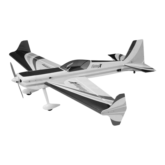
FuntanaX 50 ARF
Specifications
Wingspan: ..................................... 56 in (1422mm)
Length: .......................................... 56 in (1441mm)
Wing Area: ......................... 714 sq in (46.1 sq dm)
Assembly mAnuAl
Weight: ............................ 4–5.5 lb (1.8 kg–2.5 kg)
Radio: .................................. 4-channel w/5 servos
Engines: ........... 32–.46 2-stroke, .40–.72 4-stroke
Advertisement
Table of Contents

Related Manuals for Hangar 9 FuntanaX 50


Summary of Contents for Hangar 9 FuntanaX 50
- Page 1 FuntanaX 50 ARF Assembly mAnuAl Specifications Wingspan: ........56 in (1422mm) Weight: ......4–5.5 lb (1.8 kg–2.5 kg) Length: .......... 56 in (1441mm) Radio: ........4-channel w/5 servos Wing Area: ......714 sq in (46.1 sq dm) Engines: ... 32–.46 2-stroke, .40–.72 4-stroke...
-
Page 2: Table Of Contents
Contents Covering Colors ..............2 Introduction. -
Page 3: Introduction
Introduction The FuntanaX 50 can do it all—harriers, torque rolls, blenders, and almost anything else you can dream up. It’s all possible, thanks to an extremely lightweight, all-wood airframe and big control surfaces that give the FuntanaX 50 a very impressive thrust-to-weight ratio and crisp control authority at any airspeed. -
Page 4: Limited Warranty & Limits Of Liability
Limited Warranty Period Horizon Hobby, Inc. guarantees this product to be free from defects in both material and workmanship at the date of purchase. Limited Warranty & Limits of Liability Pursuant to this Limited Warranty, Horizon Hobby, Inc. will, at its option, (i) repair or (ii) replace, any product determined by Horizon Hobby, Inc. -
Page 5: Inspection Or Repairs
Inspection or Repairs If your product needs to be inspected or repaired, please call for a Return Merchandise Authorization (RMA). Pack the product securely using a shipping carton. Please note that original boxes may be included, but are not designed to withstand the rigors of shipping without additional protection. -
Page 6: Warranty Information
Required Tools and Adhesives Tools • Canopy Scissors • Drill • Drill bit: 1/16" (1.5mm), 1/8" (3mm) • Flat blade screwdriver • Foam: 1/4" (6mm) • Hobby knife • Masking tape • Phillips screwdriver (large) • Phillips screwdriver (small) • Pliers •... -
Page 7: Required Field Equipment
Before Starting Assembly Before beginning the assembly of the FuntanaX 50, remove each part from its bag for inspection. Closely inspect the fuselage, wing panels, rudder, and stabilizer for damage. If you find any damaged or missing parts, contact the place of purchase. -
Page 8: Section 1: Stabilizer Installation
Section 1: Stabilizer Installation Required Parts Step 2 • Wing • Fuselage Measure and mark a centerline on the • 1/4-20 x 2" nylon bolt (2) stabilizer using a felt-tipped pen. • Horizontal stabilizer • Elevator • Carbon fiber tail support rods Required Tools and Adhesives •... - Page 9 Section 1: Stabilizer Installation Step 4 Step 7 Drill a 1/16" (1.5mm) hole in the center of each hinge Slide the stab into the fuselage. Center the stab slot. Drill holes for both the elevator and stabilizer. in the opening by measuring the distance from the fuselage to each tip.
- Page 10 Section 1: Stabilizer Installation Hint: A soldering iron or hot knife can be used Step 9 as an option to the standard hobby knife. The last alignment step is making sure the wing and stabilizer are parallel. If they are not, lightly Cool Tip: Use a little rubbing alcohol and sand the opening in the fuselage for the stab a paper towel to remove those felt-tipped...
-
Page 11: Section 2: Vertical Fin Installation
Section 2: Vertical Fin Installation Required Parts Step 3 • Wing • Fuselage Use a ruler to draw two lines from the end of the slot • Vertical stabilizer onto the fuselage as shown. Use a sharp hobby knife to remove the covering from between the lines. -
Page 12: Section 3: Hinging The Ailerons
Section 3: Hinging the Ailerons Required Parts Step 4 • Wing • CA hinges (10) Slide the aileron and wing together. The gap • Aileron (left and right) between the aileron and wing should be infinitely small, approximately 1/64" (.4mm). Required Tools and Adhesives •... - Page 13 Section 3: Hinging the Ailerons Note: Do not use CA accelerator during Step 8 the hinging process. The CA must be Move the aileron up and down several times to work allowed to soak into the hinge to provide in the hinges and check for proper movement.
-
Page 14: Section 4: Rudder And Elevator Installation
Section 4: Rudder and Elevator Installation Required Parts Step 3 • Fuselage assembly • CA hinge (3) Apply a light coat of petroleum jelly onto the tail gear wire • Elevator (left and right) • Rudder where the bearing will ride. This is done to prevent the epoxy from sticking to the wire and bearing, which would •... - Page 15 Section 4: Rudder and Elevator Installation Cool Tip: You can combine the Step 5 previous step with the following step Locate the last three CA hinges, and place if you like. This will hold the rudder T-pins in the center, as was done for the ailerons in position while the epoxy cures.
-
Page 16: Section 5: Wheel Installation
Section 5: Wheel Installation Required Parts Step 3 • Landing gear • 1" (25mm) tail wheel Attach the wheel to the axle using two wheel collars • 2 " (57mm) wheel (2) • 4-40 blind nut (2) and setscrews. The exact position of the wheel will be determined after the wheel pant is installed. - Page 17 Section 5: Wheel’s On! Step 5 Step 7 Position the wheel so it is centered in the wheel pant. Attach the tail wheel using a 5/32" wheel collar. Tighten the collars once the wheel has been positioned. Note: Use threadlock on all the setscrews to ...
-
Page 18: Section 6: Engine Installation
Section 6: Engine Installation Required Parts Step 2 • Fuselage assembly • Engine mount (2) Position the engine on the mount. Adjust the engine • 6-32 x 3/4" screw (4) • Fuel tank so the distance from the firewall to the drive washer is "... - Page 19 Section 6: Engine Installation Step 4 Step 6 Attach the engine using four #6 x 5/8" Test fit the throttle pushrod tube through the firewall socket head sheet metal screws. and into the fuselage. Once satisfied with the fit, roughen the tube using sandpaper.
- Page 20 Section 6: Engine Installation Step 7 Step 10 Slide a clevis retainer onto a nylon clevis. Move the carburetor to the half-throttle position. Thread a clevis onto an 18 " (460mm) Mark the pushrod where it crosses the throttle pushrod wire, a minimum of 10 turns.
- Page 21 Section 6: Engine Installation Step 11 Step 13 Remove the clevis from the pushrod. Slide Look at the side of the fuel tank to determine which the pushrod into the pushrod tube from the direction the vent line is facing. It will be installed firewall.
-
Page 22: Section 7: Cowling Installation
Section 7: Cowling Installation Required Parts Step 3 • Fuselage assembly • Cowling Remove the cowl and remove the necessary material • #2 x 1/2" sheet metal screw (4) to fit the cowl over the engine. Install the engine back onto the firewall, and test fit the cowl over the engine. - Page 23 Section 7: Cowling Installation Step 5 Step 8 Use the cardstock from Step 1 to locate the positions Remove a section of the cowl bottom to for the cowling screws. The goal is to drill into the allow air to escape the cowling. firewall for the four screws that hold the cowling.
-
Page 24: Section 8: Servo Installation
Section 8: Servo Installation Required Parts Cool Tip: Place a drop of thin CA onto each screw hole to harden the wood around the hole. Allow the CA • Fuselage assembly • Wing assembly to fully cure before installing the servos. •... - Page 25 Section 8: Servo Installation Step 7 Step 9 Attach a 9" (229mm) servo extension to the aileron servo. Repeat Steps 6 through 8 for the other aileron servo. Tie the string inside the wing onto the servo extension. ...
-
Page 26: Section 9: Linkage Installation
Section 8: Servo Installation Step 12 Step 13 Mount the radio switch in the side of the fuselage. Route the antenna to the rear of the fuselage using the preinstalled antenna tube. Section 9: Linkage Installation Required Parts ... - Page 27 Section 8: Servo Installation Step 3 Step 5 Drill three 3/32" (2.5mm) holes through the elevator Physically place the elevator control surface at the locations marked in the previous step. Place in neutral. Mark the pushrod where it 2–3 drops of thin CA into the hole to harden the crosses the holes in the servo arm.
- Page 28 Section 8: Servo Installation Step 7 Step 9 Slide the wire through the outer hole in the elevator Slide a clevis retainer onto a nylon clevis. Thread a clevis servo arm. Secure the wire using a nylon wire keeper. onto a 7 "...
- Page 29 Section 8: Servo Installation Step 12 Step 14 Install one of the #2 x 3/4" screws in a hole Center the aileron servo electronically using the radio drilled, and then remove it. Place 2–3 drops of system.
-
Page 30: Section 10: Final Assembly
Be careful not to remove the line from the fuselage. Note: The side force generators can be removed in a few seconds. Try your FuntanaX 50 with and without them to decide which setup suits your flying style best. -
Page 31: Center Of Gravity
We recommend only one rate the widest part of the elevator, rudder, setting for the FuntanaX 50. As you become more familiar and aileron unless noted otherwise. with the handling of your model, you may wish to add a Once the control throws have been set, slide second rate setting. -
Page 32: Preflight At The Field
Preflight at the Field Charge both the transmitter and receiver pack for your airplane. Use the recommended charger supplied with your particular radio system, following the instructions provided with the radio. In most cases, you should charge your radio the night before going out flying. Check the radio installation and make sure all the control surfaces are moving correctly (i.e. -
Page 33: Notes
Notes:... -
Page 34: 2006 Official Ama National Model Aircraft Safety Code
2006 Official AMA National Model Aircraft Safety Code GENERAL 7) I will not operate models with pyrotechnics (any device that explodes, burns, or propels a projectile 1) I will not fly my model aircraft in sanctioned of any kind) including, but not limited to, rockets, events, air shows or model flying demonstrations explosive bombs dropped from models, smoke until it has been proven to be airworthy by having... - Page 35 2006 Official AMA National Model Aircraft Safety Code 5) Flying sites separated by three miles or more Organized RC Racing Event are considered safe from site-to site interference, 10) An RC racing event, whether or not an AMA Rule even when both sites use the same frequencies. Any Book event, is one in which model aircraft compete circumstances under three miles separation require in flight over a prescribed course with the objective of...
- Page 36 © 2006 Horizon Hobby, Inc. 4105 Fieldstone Road Champaign, Illinois 61822 (877) 504-0233 horizonhobby.com 8685...
Need help?
Do you have a question about the FuntanaX 50 and is the answer not in the manual?
Questions and answers