
Related Manuals for Champion Power Equipment 100136


Summary of Contents for Champion Power Equipment 100136
- Page 1 DANGER: Not intended for use in critical life support application. DANGER: Generator must be installed and operated outdoors only.
-
Page 2: Product Registration
No part of this publication may be reproduced or used in any form by any means – graphic, electronic or mechanical, including photocopying, recording, taping or information storage and retrieval systems – without the written permission of Champion Power Equipment (CPE). Have questions or need assistance? -
Page 3: Table Of Contents
Hour Meter ......34 © 2015 Champion Power Equipment Part No. 101308 Rev. A... - Page 4 Bottom Row ......36 This manual must be used with Champion Power Equipment Engine Controller .
-
Page 5: Introduction
This generator is not intended for use in critical life support applications. Proper sizing of the generator is required to ensure proper operation of appliances. Some appliances require additional wattage to start and must be considered. © 2015 Champion Power Equipment Part No. 101308 Rev. A... -
Page 6: Hsb Models
: Flexible fuel line connector, absorbs vibration when connected to rigid piping Champion Power Equipment is a market leader in power generation equipment. Champion has years of experience designing and manufacturing dependable and durable power products designed and engineered in the US to the exacting standards of the North American market. -
Page 7: General Information, Standards And Codes
470 Atlantic Avenue, Boston, Ma. 02210 NFPA NO . 58, AMERICAN NATIONAL STANDARD FOR STORAGE AND HANDLING OF LIQUID PETROLEUM GAS National Fire Protection Association 470 Atlantic Avenue, Boston, Ma. 02210 © 2015 Champion Power Equipment Part No. 101308 Rev. A... -
Page 8: Safety
Model 100136 SAFETY SAFETY SYMBOL DEFINITIONS This is the safety alert symbol. It is used to alert you to potential physical injury hazards. Obey all safety messages that follow this symbol to avoid Black hazard pictorial on yellow possible injury or death. -
Page 9: Installation Hazards
Before welding components on the generator, contact CPE for recommended welding instructions. Wear eye protection WARNING Not intended for use in critical life support applications. Wear personal protective equipment Do not leave tools in the area © 2015 Champion Power Equipment Part No. 101308 Rev. A... -
Page 10: Before Starting
Model 100136 SAFETY BEFORE STARTING OPERATING HAZARDS CAUTION WARNING Before starting, operating and ALWAYS operate the generator maintaining this generator, be sure following the manufacturer’s to read and understand the content instructions. Operating the generator and safety messages in this manual. -
Page 11: Accidental Starting
• Light-headedness, dizziness • Physical fatigue, weakness in joints and muscles • Sleepiness, mental fatigue, inability to concentrate or speak clearly, blurred vision • Stomachache, vomiting, nausea © 2015 Champion Power Equipment Part No. 101308 Rev. A... -
Page 12: Electrical Shock Hazards
Model 100136 SAFETY FIRE/EXPLOSION HAZARDS Carbon monoxide poisoning is possible if someone is experiencing any of these symptoms. Seek fresh air immediately. DO NOT sit, lie down or fall asleep. Alert others to the possibility WARNING of carbon monoxide poisoning. If the affected person does not improve within minutes of breathing fresh air, call 911 immediately. -
Page 13: Burn Hazards
BATTERY HAZARDS WARNING Always read and comply with the battery manufacturer’s recommendations for procedures concerning proper battery use and maintenance. © 2015 Champion Power Equipment Part No. 101308 Rev. A... -
Page 14: Safety Labels On Unit
Model 100136 SAFETY SAFETY LABELS ON UNIT Poisonous Gas Hazard Generator exhaust Fire Hazard ALWAYS keep the surrounding contains carbon monoxide. Breathing carbon Burn Hazard DO NOT area near generator clean and free of debris Burn Hazard DO NOT touch hot monoxide will cause nausea, dizziness, and and/or dry vegetation. -
Page 15: Safety, Serial/Model, Nameplate Label Locations
SAFETY, SERIAL/MODEL, NAMEPLATE LABEL LOCATIONS The safety labels have specific placement and must be replaced if they are unreadable, damaged or missing. (inner part of cover) A) Serial number location B) Nameplate © 2015 Champion Power Equipment Part No. 101308 Rev. A... -
Page 16: Placement And Installation Guidelines For Champion 12.5Kw Home Standby Generator To Reduce The Risk Of Fire
Model 100136 SAFETY PLACEMENT & INSTALLATION GUIDELINES FOR CHAMPION 12 .5KW HOME STANDBY GENERATOR TO REDUCE THE RISK OF FIRE NATIONAL FIRE PROTECTION ASSOCIATION (NFPA) STANDARD NFPA 37 REQUIREMENTS AND TESTING REQUIREMENTS: ANNEX A EXPLANATORY MATERIAL NFPA 37 2010, section 4.1.4, Engines Located Outdoors. -
Page 17: Specifications
Engine start sequence Standard Starter lockout Standard Battery charger/low battery indicator Standard Charger fault Standard AVR over voltage protection Standard Low oil protection Standard Safety fused Standard Overcrank/overspeed/underspeed protection Standard © 2015 Champion Power Equipment Part No. 101308 Rev. A... -
Page 18: Champion 717Cc Engine
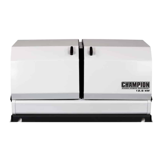
Model 100136 SPECIFICATIONS CHAMPION 717CC ENGINE The 717cc engine was developed by Champion Engine Technology for use in Champion home standby generators. The V-Twin cylinder design provides high output, efficient operation, low maintenance and demonstrated long life. Based on the engine’s power, performance and reliability, it was selected to power the 12.5kW Champion Home Standby Generator. This engine design has been used in production since 2015. -
Page 19: Alternator Overview
(+) brush and slip ring. The excitation and field boost current passes through the windings and to the frame ground via the negative (-) slip ring and brush, and the BLACK wire. © 2015 Champion Power Equipment Part No. 101308 Rev. A... -
Page 20: Unpacking
Model 100136 UNPACKING UNPACKING WARNING The generator weighs more than 400 lb. (181 kg). Use the aid of additional assistants and exercise caution during installation. Inspect the generator for damaged or loose parts. DO NOT operate the generator if any components are damaged or loose. -
Page 21: Installation
Install the unit in a location where the sump pump discharge, Before installing the generator, review SAFETY section starting rain gutter downspouts, roof run off, landscape irrigation, natural page 8 © 2015 Champion Power Equipment Part No. 101308 Rev. A... -
Page 22: Preparation
Model 100136 INSTALLATION ponding or water sprinklers will not flood the unit or spray the DANGER enclosure entering any inlet or outlet opens. Position the unit in an area where prevailing winds will carry Running engines give off carbon the exhaust gas away from any potentially occupied building or monoxide, an odorless, colorless, structure. -
Page 23: Placement
HSB base. The HSB must be lifted cables DO NOT touch/contact the HSB. from the wood pallet to separate. © 2015 Champion Power Equipment Part No. 101308 Rev. A... -
Page 24: Instalation Preparation
Model 100136 INSTALLATION Once the HSB has been placed, check to make sure it is level. If CAUTION it isn’t, make adjustments prior to installation procedures start. Never operate the HSB with the engine oil level below the “ADD” mark on the dipstick, doing so could damage the engine. -
Page 25: Fuel Consumption
Fire Marshall for guidance on proper local codes and installations. All piping must comply with NFPA 54 and related codes. Gas line connections should be made by a certified plumber familiar with local codes. © 2015 Champion Power Equipment Part No. 101308 Rev. A... - Page 26 Model 100136 INSTALLATION Always use AGA approved gas pipe and a quality pipe sealant flexible gas line according to local codes. The flexible gas line or joint compound. The piping should conform to federal and also protects against settlement between the HSB pad and the local codes, rigidly mounted and protected from vibration.
-
Page 27: Lpg Vapor Pipe Sizing
The LPG must be a vapor withdrawal system. The HSB will not work on a liquid withdrawal system. Gas line connections should be made by a certified plumber familiar with local codes. © 2015 Champion Power Equipment Part No. 101308 Rev. A... -
Page 28: Converting To Lpg
Model 100136 INSTALLATION CAUTION Check for leaks by spraying all connection points with a soap solution made of dishwashing soap and water. If you see soap bubbles, this would be an indication of a leak and it should be corrected. Check each connection point, there should not be a visible bubbling with the soap solution applied. -
Page 29: Full Fuel Shut Off
HSB shut-off valve as close to the inlet as possible in accordance with local codes. Connect breather tube (1) to breather port and put clamp (2) on breather tube. 1 . MAIN JETS 2 . LOW SPEED JETS © 2015 Champion Power Equipment Part No. 101308 Rev. A... -
Page 30: Checking Pressure With Amanometer
Model 100136 INSTALLATION 8 . CHECKING PRESSURE WITH A Champion HSB units have been run and tested at the factory. They do not require any type of break-in period. MANOMETER This check should only be done when the HSB and ATS have 9 . -
Page 31: 2015 Champion Power Equipment
When the HSB is running (during use), the engine provides power to the battery charger, charging the batteries to maintain full battery power. © 2015 Champion Power Equipment Part No. 101308 Rev. A... -
Page 32: Flexible Fuel Line
Model 100136 INSTALLATION FLEXIBLE FUEL LINE CAUTION A flexible fuel line (enclosed with the HSB) is to be installed Do not dispose of battery or batteries in a fire. The between the stationary fuel supply line pipe and the fuel inlet battery is capable of exploding. -
Page 33: Identify/Select Standby Circuits
The installation must comply fully with all applicable codes on the outlets feeding your sensitive equipment. Surge standards and regulations. suppressors come in single or multi-outlet styles. They’re designed to protect against virtually all short-duration voltage fluctuations © 2015 Champion Power Equipment Part No. 101308 Rev. A... -
Page 34: Hour Meter And Over Voltage Protection
Model 100136 INSTALLATION HOUR METER & OVER VOLTAGE SET EXERCISE TIME PROTECTION To set the exercise time, The Engine Control Module switch must be in the ATS HOUR METER mode. Decide on the desired day and time to exercise the HSB The hour meter keeps track of all running time of the HSB. -
Page 35: Engine Relay Module
CONNECTOR #3 (far right), has 2 leads. The top lead is BROWN, when connected it runs to pre-boost/magnetized pin #7 on the Engine Controller Module. The bottom lead is GREEN and runs to ground. © 2015 Champion Power Equipment Part No. 101308 Rev. A... -
Page 36: Top Row
Model 100136 INSTALLATION Position #3 O (ORANGE) Position #4 Exercise O/B (ORANGE/BLACK) Position #5 High Engine Br (BROWN) Temp Position #6 Low oil level/ Y (YELLOW) pressure Position #7 NOT CONNECTED EMPTY Position #8 Fuel supply valve G/B (GREEN/BLACK) Position #9... -
Page 37: 2015 Champion Power Equipment
LOW BATTERY LED The YELLOW LED will be lit if the battery voltage fell below 21.0 volts for at least one minute while the engine was running. If © 2015 Champion Power Equipment Part No. 101308 Rev. A... -
Page 38: Pin Locations
Model 100136 INSTALLATION LOW OIL LED In all cases when the LED is GREEN, this is an indicator that the HSB is performing properly. The RED LED will be lit when the engine oil level drops below the safe operating level. When this fault is detected, the HSB In all cases when the LED is RED, this is an indicator that the will shut down and re-start will be disabled. -
Page 39: Ats Control Module
This is a two (2) wire start system. The control of HSB operation and ATS operation are done through the controls in the HSB. This is done by a wire connection to the HSB and then a wire © 2015 Champion Power Equipment Part No. 101308 Rev. A... -
Page 40: Pin Locations
Model 100136 INSTALLATION OFF – This position will not allow any power to be delivered or 14. Pin 14 Load AC Detect Br (Brown) transferred to the ATS or the household when the engine (HSB) 15. Pin 15 Gen AC Detect B (Black) is running. -
Page 41: Hsb Test
With the Engine Control Module and ATS Module both in the OFF position. Turn ON the utility power supply to the ATS. © 2015 Champion Power Equipment Part No. 101308 Rev. A... - Page 42 Model 100136 INSTALLATION With an AC voltmeter, check for the correct voltage. Frequency 63 Hertz Single-phase utility power supply. Measure across the Terminals L1 to L2 230 VAC UTILITY SUPPLY ATS terminal lugs L1 and L2. Also check Terminals L1 to NEUTRAL 115 VAC L1 to NEUTRAL and L2 to NEUTRAL.
-
Page 43: Hsb Test Under Load
With rated load applied, check voltage and frequency across ATS GENERATOR SUPPLY terminals L1 and L2. Voltage should be greater than 216 Volts. Frequency should be greater than 57 Hertz. © 2015 Champion Power Equipment Part No. 101308 Rev. A... -
Page 44: Customer Familiarization Summary
Model 100136 INSTALLATION CUSTOMER FAMILIARIZATION- NOTICE SUMMARY By law it is required in many states to have a Carbon Monoxide (CO) detector in operating condition in your It’s important to educate the home owner on proper home. Carbon Monoxide detector(s) must be installed maintenance, operation and service call procedures. -
Page 45: Hsb, Ats Model & Serial Reference Ats Back-Up Circuits
ATS circuits powered ______________________________________ ____________________________ ____________________________ ____________________________ ____________________________ ____________________________ ____________________________ ____________________________ ____________________________ ____________________________ ____________________________ ____________________________ ____________________________ ____________________________ ____________________________ Date Installed _____________________________________ Dealer/Installer _____________________________________________________ Address _____________________________________________________ _____________________________________________________ Phone _____________________________________________________ Cell _____________________________________________________ Purchased from _____________________________________________________ © 2015 Champion Power Equipment Part No. 101308 Rev. A... -
Page 46: Automatic Transfer Switch
Model 100136 INSTALLATION AUTOMATIC TRANSFER SWITCH The ATS is also equipped with manual transfer switch operation which is generally utilized for system checks and function tests (ATS) of the system, refer to manual. Refer to the Reliance instruction guide enclosed with each unit... -
Page 47: Electrical Grommet(S)
Conductors must be properly circuit breaker. Repeat for each of the selected circuits. supported, of approved insulation materials, protected by © 2015 Champion Power Equipment Part No. 101308 Rev. A... -
Page 48: Installing Communication Wires
Model 100136 INSTALLATION The branch conductors must be connected to the same ampacity (size) breakers as they were when they were in the main panel. Make sure that the total ampacity of the selected circuits does not exceed the maximum capacity of the generator. -
Page 49: Ats Circuit Board Fuse Information
F4 Load Buss L2 out of the 24 VDC power supply to terminal 1. If the solenoid clicks and the mechanism transfers, fuse F1 is functional. F5 Load Buss L1 out F6 Generator solenoid © 2015 Champion Power Equipment Part No. 101308 Rev. A... -
Page 50: Fuse F6
Model 100136 INSTALLATION Disconnect the 24 VDC power supply and reconnect the wires that were installed in terminals 1, 2 and 3, in the correct order. FUSE F6 If the system controller will switch the transfer switch from utility to HSB generator and back, fuse F6 is functional. -
Page 51: Troubleshooting Hsb
Champion or Champion service dealer*. Engine high/over temperature shut down Check all intake and exhaust ventilation around the HSB, remove all debris. Let HSB sit for 30 minutes to cool down. © 2015 Champion Power Equipment Part No. 101308 Rev. A... -
Page 52: Troubleshooting
This will reset fault LED, however if a fault code(s) re-occurs it must be addressed. BATTERY(S) NO OR LOW LEVEL CHARGED, BATTERY(S) DEAD, NEEDS REPLACEMENT, THE EXERCISE TIME MUST BE RESET ONCE THE BATTERY(S) HAVE BEEN DISCONNECTED . *Contact Champion Power Equipment, Technical Service toll free 1-877-338-0999, tech@championpowerequipment.com or your nearest Champion dealer. www.championpowerequipment.com... - Page 53 Champion Power Equipment 12039 Smith Ave. Santa Fe Springs, CA 90670 USA Made in China...
-
Page 54: Year Limited Warranty
For a period of 5 years or 2000 hours (whichever occurs first) from successful activation by an Authorized Champion Home StandbyDealer, Champion Power Equipment will, at its option, repair or replace any part(s) which upon examination, inspection and testing by Champion Power Equipment or an Authorized Champion Home Standby Dealer is found to be defective under normal use and service, in accordance with the Warranty Schedule set forth below. - Page 55 THIS WARRANTY SHALL NOT APPLY TO THE FOLLOWING: Original installation or start-up costs Champion Home Standby generators that utilize non-Champion Power Equipment replacement parts Costs of normal maintenance (i.e. tune-ups, associated part(s), adjustments, loose/leaking clamps, installation and start-up) Units sold, rated or used for "Prime Power", "Trailer Mounted" or "Rental Unit" applications...
- Page 56 Purchaser/owner also may have other rights that vary from state to state. To obtain warranty service or your nearest Champion Home Standby Dealer call Champion Power Equipment Customer Service toll free 1-877-338-0999, Monday - Friday from 8:30 AM - 5:00 PM (PST/PDT).
Need help?
Do you have a question about the 100136 and is the answer not in the manual?
Questions and answers