
Subscribe to Our Youtube Channel
Related Manuals for Champion Power Equipment 73531i


Summary of Contents for Champion Power Equipment 73531i
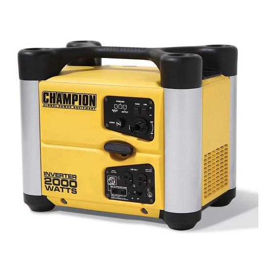
- Page 1 Champion Power Equipment 2000 W Inverter Service Manual 73531i 73552i Draft, 08‐23‐2010 Page 1 ...
-
Page 2: Table Of Contents
Table of Contents 1.0 Specifications ............................... 4 2.0 Service Information .................... Error! Bookmark not defined. 2.1 Maintenace Schedule ............................ 5 3.0 Troubleshooting .............................. 6 3.1 Engine ................................ 6 3.1.1 Engine will not start .......................... 6 3.1.2 Engine starts, but will not run ........................ 7 3.1.3 Engine RPM are low or not steady ...................... 7 3.2 Ignition System .............................. 8 3.2.1 No Spark .............................. 8 3.3 Throttle Control System ............................ 8 3.3.1 Engine RPM not steady .......................... 8 3.3.2 ECON switch does not work ........................ 9 3.4 Generator ................................ 9 3.4.1 Low AC output ............................ 9 4.0 Maintenance .............................. 10 4.1 Check Oil Level ............................ 10 4.2 Change Engine Oil ............................ 10 4.3 Air Cleaner .............................. 10 4.4 Spark Plug ... - Page 3 4.9 Engine Switch / Econ Switch ........................ 13 4.10 Ignition Unit ............................. 14 4.11 Oil Level Switch ............................ 14 4.12 AC Receptacle ............................ 14 4.13 Stepper Motor ............................ 15 4.14 Generator .............................. 15 4.15 Trigger .............................. 15 4.16 Ignition Coil .............................. 15 4.17 Valve Stem Outside Diameter ........................ 16 4.18 Valve Spring Free Length.......................... 16 4.19 Cam Height ............................... 16 4.20 Cylinder ‐ Inner Diameter ......................... 16 4.21 Piston Skirt – Outside Diameter ....................... 17 4.22 Piston Pin – Outside Diameter ......................... 17 4.23 Piston Ring – Side Clearance ........................ 17 4.24 Crankshaft Pin – Outside Diameter ...................... 17 4.25 Carburetor Float Height ........................... 17 Draft, 08‐23‐2010 Page 3 ...
-
Page 4: Specifications
1.0 Specifications Overall Length 19.3 in / 490 mm Overall Width 13.2 in / 335 mm Dimensions Overall Height 16.3 in / 415 mm Dry Weight 48 lbs / 21.7 kg Generator type Multi pole rotation Generator Self-ventilation drip-proof structure alternator Excitation Self-excitation (Magnet type) -
Page 5: Maintenace Schedule
2.0 Maintenance Schedule Interval Every First 20 Hr Every 100 300 Hr or Item Routine or First Hr or 6 Month Months Months Check oil level in engine Engine oil Replace engine oil ● ● Check fuel leakage Fuel system Clean fuel filter / strainer ●... -
Page 6: Troubleshooting
3.0 Troubleshooting 3.1 Engine 3.1.1 Engine will not start 1. Check that the Engine Switch is in ON position 2. Check the Engine Oil level. If low, the Low Oil Sensor will ground the Spark Plug. 3. Check that the Fuel Valve is turned to ON position 4. Check that the Choke is pulled completely out (full choke) 5. Check that the fuel level in tank is at adequate 6. Check that the Vent in the Fuel Cap is turned to ON 7. Check to see if there is fuel in the Carburetor a. If no fuel in Carburetor, check fuel line for blockage 8. Is the Spark Plug wet or dry? a. If Wet – dry it off and try to start engine b. If Dry – Check Carburetor port and nozzle 9. Check Spark strength a. If weak – See Ignition System trouble shooting 10. Check Compression: 116‐138 psi @ 1100 rpm and 58‐72 psi @ 600 rpm a. If pressure is high – Check head cylinder carbon b. If pressure is low – Check Valve Clearance Draft, 08‐23‐2010 Page 6 ... -
Page 7: Engine Starts, But Will Not Run
3.1.2 Engine starts, but will not run 1. Check that the fuel level in tank is adequate 2. Check that the Fuel Valve is turned to completely to ON position 3. Check fuel filter – clean or replace 4. Check Fuel Hose for blockage or damage. Clean or replace if needed. 5. Check Carburetor gasket for damage and confirm nuts are tight. 6. Check Compression: 116‐138 psi @ 1100 rpm and 58‐72 psi @ 600 rpm a. If High – Check head cylinder carbon b. If low – Check valve clearance 7. Check air gap of Pulser Coi: 1.0mm (0.040 in) gap a. Adjust if needed 8. Check Pulser Coil. Replace if needed. 9. If engine will still not run, see Throttle Control trouble shooting 3.1.3 Engine RPM are low or not steady 1. Check Air Filter element. Clean or replace if dirty needed. 2. Check Valve Clearance – 0.1mm (.004 in) a. Adjust if needed 3. Check Spark Plug – clean or replace if needed 4. Check Main Jet Choke – clean as needed 5. Check Carburetor Joint and Gasket for damage and confirm nuts are tight. 6. -
Page 8: Ignition System
3.2 Ignition System 3.2.1 No Spark 1. Check the Low Oil Sensor (confirm crankcase is full). Disconnect the Low Oil Sensor wire and check for spark a. If the Spark Plug sparks, then the Low Oil Sensor needs to be replaced 2. Install a new Spark Plug and check for spark 3. Pull recoil starter and check if the Oil Warning Light flashes a. The flashing Oil Warning Light indicates that the Oil Level Sensor needs replacing 4. Check Engine Switch for continuity a. Replace if needed 5. Check air gap and resistance of the Pulsar Coil <need spec from Yamashita> a. Adjust air gap or replace Pulsar Coil if needed 6. Check Ignition Coil <need detail> a. Replace if needed 7. Check Wire harness for damage a. Replace if needed 3.3 Throttle Control System 3.3.1 Engine RPM not steady 1. Check Stepper Motor movement a. Starting: Full Open close b. Stopping: Full Open c. Replace Stepper Motor if needed 2. Check Stepper Motor Resistance: 40‐50 ohms a. -
Page 9: Econ Switch Does Not Work
3.3.2 ECON switch does not work 1. Check Stepper Motor Resistance: 232 ‐ 267 ohms (20 degrees C) 2. Check ECON Switch for continuity a. Replace if needed 3. Check Wire Harness for damage a. Replace if needed 4. Replace Control Unit 3.4 Generator 3.4.1 Low AC output 1. With Engine running, check if the Overload light is ON a. If Overload light is ON – remove overload. If light stays ON, replace the Control Unit 2. Check Engine RPM a. ECON ON: less than 3000 rpm b. ECON OFF: 4300 rpm 3. Check Wire Harness Connector 4. Check Main Coil voltage: 228 – 342 V AC a. Low voltage: Replace Rotor b. No voltage: Check Main Coil resistance – 1.2 Ohm ±0.24 i. If resistance out of spec, replace Stator 5. Check Sub Coil Voltage: 228 – 342 V AC (20 degrees C) a. Low voltage: Replace Rotor b. -
Page 10: Maintenance
4.0 Maintenance 4.1 Check Oil Level 1. Stop the engine and place the unit on a level surface 2. Remove the Maintenance Cover (4 screws) 3. Remove the Oil Filler Cap/Dipstick 4. Check the oil level on the Cap/Dipstick. Add oil if the dipstick does not reach the oil level. 4.2 Change Engine Oil 1. It is best to change the oil when it is warm. Start the unit and let it run for 4‐5 minutes to warm the oil. 2. Stop the engine and place the unit above an appropriate oil collection pan. 3. Remove the Maintenance Cover and remove the Oil Filler Cap/ Dipstick. 4. Tilt the unit towards its side to allow the oil to drain completely 5. Place the unit back in the upright position 6. Add approximately 0.4 liter. Use the Cap/Dipstick to check for proper level. 7. Replace the Maintenance Cover. 4.3 Air Cleaner 1. Stop the engine and remove the Maintenance Cover. 2. Remove the Air Cleaner Cover (1 screw) 3. Remove the foam Air Cleaner element. Wash foam element in warm soapy water, rinse, and dry. 4. Saturate the clean element in clean engine oil. Squeeze out any excess oil. 5. Replace the foam element in the unit. 6. Inspect the seals on the Air Cleaner Cover. Clean as needed. Replace and fasten Cover. 7. Replace the Maintenance Cover. NOTE: ... -
Page 11: Spark Plug
4.4 Spark Plug 1. Stop the engine and remove the Maintenance Cover. 2. Remove the Spark Plug Maintenance Cap on top of the unit. 3. Disconnect the Spark Plug Wire. 4. Remove the Spark Plug. The Spark Plug Maintenance Cap provides tool access. 5. Remove carbon or other deposits with a wire brush 6. Measure the spark plug gap and adjust as needed. 0.6 – 0.7mm (0.024” – 0.028”) 7. If needed, replace spark plug with E6RTC (NHSP) or BPR6HS (NGK) 8. Install the new spark plug by until finger tight to seat the washer. Then use a plug wrench and torque the new spark plug to 20 N‐m (14.4 ft‐lb) 9. Replace the spark plug wire. 10. Replace the Spark Plug Maintenance Cap. 11. Replace the Maintenance Cover. 4.5 Valve Clearance NOTE: Valve clearance MUST be checked while the engine is cold 4.5.1 Measuring Valve Clearance 1. Remove the Maintenance Cover. 2. Remove the Handle 3. Remove the Top Cover 4. Remove the Fuel Tank 5. Disconnect the spark plug wire 6. Remove the Spark Plug a. -
Page 12: Adjusting Valve Clearance
a. Torque to 11 N‐M (7.9 ft‐lb) when putting the unit back together 10. Remove the Cylinder Head Cover Gasket 11. Remove Air Shroud 12. Rotate the Rotor clockwise until the Piston is at top dead center 13. Measure the Valve clearance by inserting a feeler gage between the Rocker Arm and the Valve a. Both Intake and Exhaust Valves must be 0.1mm (0.004”) clearance 4.5.2 Adjusting Valve Clearance 1. Loosen the Adjusting Screw Lock Nut 2. Turn the Adjusting Screw in or out as needed 3. Hold the Adjusting Screw with a wrench and torque the Lock Nut to 7 N‐m (5.1 ft‐lb) 4. Measure the Valve clearance to verify it is correct. Repeat as needed. 5. Assemble the unit by performing steps 1‐11 of section 4.5.1 in reverse order 4.6 Fuel Filter Danger ‐ Gasoline is highly flammable. It can cause serious burns. Keep heat, flame, and sparks away. Clean up any spills immediately. 1. Remove the Fuel Cap 2. Remove the wire mesh Fuel Filter 3. Clean the Fuel Filter to remove any obstructions 4. Inspect for damage. Replace if needed. 5. Install the Fuel Filter and Fuel Cap ... -
Page 13: Spark Arrestor
2. Remove the Knob of the Fuel Valve 3. Remove the Handle 4. Remove the Top Cover 5. Remove the (3) screws that hold the Fuel Tank in place. 6. Lift the Fuel Tank and disconnect the fuel line from the Fuel Tank 7. Drain the Fuel tank into an appropriate container. 8. Remove the Fuel Strainer from the Fuel tank (Fuel Strainer is connected to the Fuel Valve) 9. Remove any obstructions. Inspect for damage. Replace if damaged. 10. Clean the Fuel Tank with a cleaning solvent and let it dry completely. 11. Install the Fuel Valve in the Fuel Tank. 12. Connect the fuel line to the Fuel Valve 13. Install the removed parts in the reverse order of removal. 4.8 Spark Arrestor 1. Make sure Muffler has cooled completely before servicing the Spark Arrestor 2. Remove the Handle 3. Remove the Corner Cover 4. Remove the Side Cover panel on the Muffler side of the unit. 5. Remove the Spark Arrestor from the Muffler by loosening the clamp around the muffler pipe. 6. Clean the carbon from the steel mesh of the Spark Arrestor using a stiff wire brush. 7. Check for any damage and replace if needed. 8. -
Page 14: Ignition Unit
4.10 Ignition Unit 1. Unplug the 10 Pin connector from the module. 2. Measure the resistance by connecting one test probe to the metal case of the Engine and the other test probe to the pin on the 10 pin connector. See Table 1 below for correct values. Table 1 ‐ Resistance Values Color Circuit Name Resistance Blue Primary Ignition Coil 0.8 – 1.5 Ohm No Continuity with proper Oil Yellow Oil Level Switch Level Green/White Trigger Coil 80 – 132 Ohm Yellow/Green Ground Wire Continuity Green Igniter Unit Power Coil Winding 0.5 – 0.9 Ohm No Continuity with Switch ON, Black Engine Switch Continuity with Switch OFF 4.11 Oil Level Switch 1. Place the oil alarm in the position shown below. a. There should be NO continuity between the Oil Level Switch and the Ground Wire. 2. Rotate the oil alarm 180 degrees and check continuity. a. There should be continuity between the Oil Level Switch and the Ground Wire. 3. Completely immerse the oil alarm in oil. 4. -
Page 15: Stepper Motor
4.13 Stepper Motor 1. Measure the resistance of the Stepper Motor lead‐out wires a. Between 1 and 3: 45 – 55 Ohm b. Between 2 and 4: ??? <need spec from Yamashita> 4.14 Generator 1. Ignition Coil a. Measure the resistance between the Blue terminal and Yellow/Green terminal. It should measure 0.1 – 0.2 Ohm 2. DC Coil a. Measure resistance between the two green terminals. It should measure 0.1 – 0.2 Ohm 3. Sub Coil a. Measure resistance between yellow terminals. It should measure 0.1 – 0.2 Ohm 4. AC Coil a. Measure resistance between red terminals. It should measure 1.5 – 2.0 Ohm 4.15 Trigger 1. Attach the two test probes to the Trigger and measure the resistance. It should measure 120 Ohm 24. 2. Measure the clearance between the Trigger and the Projection Part of the Rotor. The clearance should be 0.3 – 0.5mm (0.012 – 0.020”). 4.16 Ignition Coil 1. Check the Primary Resistance. a. Attach the two test probes to the primary coil plug of ignition coil. The resistance should measure 1.1 Ohm 0.22. 2. Check the Secondary Resistance. a. Attach one test probe to the Spark Plug Cap and the other probe to each terminal of the primary coil plugs of the Ignition Coil. The resistance should be 12.2K Ohm 2.4K ... -
Page 16: Valve Stem Outside Diameter
4.17 Valve Stem Outside Diameter 1. Intake Valve a. Standard: 4.948 – 4.960mm (.1948 ‐ .1953”) b. Service Limit: 4.908mm (.1932”) 2. Exhaust Valve a. Standard: 4.928 – 4.940mm (.1940 ‐ .1945”) b. Service Limit: 4.908mm (.1932”) 4.18 Valve Spring Free Length 1. Standard: 27.4mm (1.078”) 2. Service Limit: 24.4mm (.961”) 4.19 Cam Height 1. Intake A a. Standard height: 20.490 – 20.590mm (.8067 ‐ .8106”) b. Service Limit: 20.390mm (.8028”) 2. Intake B a. Standard height: 16.139 – 16.239mm (.6354 ‐ .6393”) b. Service Limit: 16.039mm (.6315”) 3. Exhaust A a. Standard height: 20.490 – 20.590mm (.8067 ‐ .8106”) b. Service Limit: 20.390mm (.8028”) 4. Exhaust B a. Standard height: 16.139 – 16.239mm (.6354 ‐ .6393”) b. -
Page 17: Piston Skirt - Outside Diameter
4.21 Piston Skirt – Outside Diameter 1. Standard: 48.574 – 48.594mm (1.9124 – 1.9132”) 2. Service Limit: 48.53mm (1.9106”) 4.22 Piston Pin – Outside Diameter 1. Standard: 11.996 – 12.000mm (.4723 – .4724”) 2. Service Limit: 11.950mm (.7854”) <ask Yamashita to verify> 4.23 Piston Ring – Side Clearance 1. Top Ring a. Standard: 0.04 – 0.08mm (.0016 – .0032”) b. Service Limit: 0.12mm (.0047”) 2. Second Ring a. Standard: 0.02 – 0.06mm (.0008 – .0024”) b. Service Limit: 0.10mm (.0039”) 4.24 Crankshaft Pin – Outside Diameter 1. Standard: 21.969 – 22.000mm (.8649 – .8661”) <ask Yamashita to verify> 2. Service Limit: 21.985mm (.8656”) 4.25 Carburetor Float Height 1. Standard: 17mm (.669”) 2. Replace the Carburetor if the Float Height is not correct Draft, 08‐23‐2010 Page 17 ...
Need help?
Do you have a question about the 73531i and is the answer not in the manual?
Questions and answers