Table of Contents
Advertisement
Quick Links
Copyright
This publication, including all photographs, illustrations and software, is protected under
international copyright laws, with all rights reserved. Neither this manual, nor any of the
material contained herein, may be reproduced without written consent of the author.
Version 1.0
Disclaimer
The information in this document is subject to change without notice. The manufacturer
makes no representations or warranties with respect to the contents hereof and specifically
disclaims any implied warranties of merchantability or fitness for any particular purpose.
The manufacturer reserves the right to revise this publication and to make changes from
time to time in the content hereof without obligation of the manufacturer to notify any
person of such revision or changes.
Trademark Recognition
Microsoft, MS-DOS and Windows are registered trademarks of Microsoft Corp.
VIA is a registered trademark of VIA Technologies, Inc.
Other product names used in this manual are the properties of their respective owners and
are acknowledged.
Federal Communications Commission (FCC)
This equipment has been tested and found to comply with the limits for a Class B digital
device, pursuant to Part 15 of the FCC Rules. These limits are designed to provide reason-
able protection against harmful interference in a residential installation. This equipment
generates, uses, and can radiate radio frequency energy and, if not installed and used in
accordance with the instructions, may cause harmful interference to radio communications.
However, there is no guarantee that interference will not occur in a particular installation.
If this equipment does cause harmful interference to radio or television reception, which
can be determined by turning the equipment off and on, the user is encouraged to try to
correct the interference by one or more of the following measures:
•
Reorient or relocate the receiving antenna
•
Increase the separation between the equipment and the receiver
•
Connect the equipment onto an outlet on a circuit different from that to which
the receiver is connected
•
Consult the dealer or an experienced radio/TV technician for help
Shielded interconnect cables and a shielded AC power cable must be employed with this
equipment to ensure compliance with the pertinent RF emission limits governing this
device. Changes or modifications not expressly approved by the system's manufacturer
could void the user's authority to operate the equipment.
Preface
Preface
Advertisement
Table of Contents

Subscribe to Our Youtube Channel
Related Manuals for Mercury KVM266PM


Summary of Contents for Mercury KVM266PM
- Page 1 Preface Copyright This publication, including all photographs, illustrations and software, is protected under international copyright laws, with all rights reserved. Neither this manual, nor any of the material contained herein, may be reproduced without written consent of the author. Version 1.0 Disclaimer The information in this document is subject to change without notice.
-
Page 2: Declaration Of Conformity
Declaration of Conformity This device complies with part 15 of the FCC rules. Operation is subject to the following conditions: • This device may not cause harmful interference, and • This device must accept any interference received, including interference that may cause undesired operation Canadian Department of Communications This class B digital apparatus meets all requirements of the Canadian Interference-causing Equipment Regulations. -
Page 3: Table Of Contents
T T T T T ABLE OF CONTENTS ABLE OF CONTENTS ABLE OF CONTENTS ABLE OF CONTENTS ABLE OF CONTENTS Preface Chapter 1 Introducing the Motherboard Introduction....................1 Feature......................2 Motherboard Components................4 Chapter 2 7 7 7 7 7 Installing the Motherboard Safety Precautions..................7 Choosing a Computer Case...............7 Installing the Motherboard in a Case............7... - Page 4 Integrated Peripherals..............34 Power Management Setup............37 PNP/PCI Configurations.............41 PC Health Status................42 Frequency/Voltage Control............43 Load Fail-Safe Defaults..............44 Load Optimized Defaults.............44 Set Supervisor/User Password............44 Save & Exit Setup Option.............45 Exit Without Saving..............45 Chapter 4 47 47 47 47 47 Using the Motherboard Software About the Software CD-ROM..............47 Auto-installing under Windows 98/ME/2000/XP........47 Running Setup................48...
-
Page 5: Introducing The Motherboard
Chapter 1 Introducing the Motherboard Introduction Thank you for choosing the KVM266PM motherboard. This motherboard is a high perfor- mance, enhanced function motherboard that supports Socket 462 AMD AthlonXP/Athlon/ Duron processors for high-end business or personal desktop markets. The motherboard incorporates the VIA KM266Pro Northbridge (NB) and VT8235 Southbridge (SB) chipsets. -
Page 6: Feature
Feature Processor The KVM266PM uses a 462-pin socket that carries the following features: • Accommodates AMD AthlonXP/Athlon/Duron CPUs • Supports a system bus (FSB) of 333/266/200MHz Chipset The KM266Pro Northbridge (NB) and VT8235 Southbridge (SB) chipset is based on an innovative and scalable architecture with proven reliability and performance. - Page 7 Two 40-pin IDE low profile headers that support four IDE devices • One floppy disk drive interface • A Communications Networking Riser (CNR) slot The KVM266PM motherboard supports Ultra DMA bus mastering with transfer rates of 133/100/66/33 MB/s. Onboard LAN (Optional) The onboard LAN provides the following features: •...
-
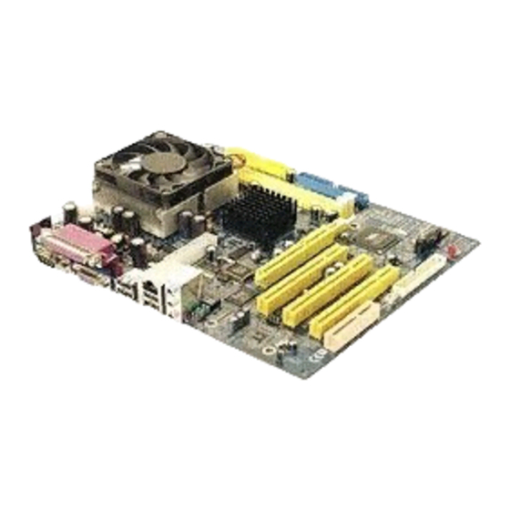
Page 8: Motherboard Components
Motherboard Components Introducing the Motherboard... - Page 9 Table of Motherboard Components LABEL COMPONENT 1 CPU Socket Socket-A(Socket-462) for AMD K7 CPUs 2 CPUFAN1 CPU cooling fan connector 3 DIM1~DIM2 184-pin DDR SDRAM slots 4 JP3 BIOS flash protect jumper 5 IDE1 Primary IDE connector 6 IDE2 Secondary IDE connector 7 FDD1 Floppy disk drive connector 8 JP8~JP9...
- Page 10 Memo Introducing the Motherboard...
-
Page 11: Installing The Motherboard
Make sure that your case supports all the features required. Secondly, KVM266PM supports one or two floppy diskette drives and four enhanced IDE drives. Make sure that your case has sufficient power and space for all drives that you intend to install. -
Page 12: Checking Jumper Settings
Do not over-tighten the screws as this can stress the motherboard. Checking Jumper Settings This section explains how to set jumpers for correct configuration of the motherboard. Setting Jumpers Use the motherboard jumpers to set system configuration options. Jumpers with more than one pin are numbered. -
Page 13: Checking Jumper Settings
Checking Jumper Settings The following illustration shows the location of the motherboard jumpers. Pin 1 is labeled. Jumper Settings Jumper Type Description Setting (default) 1-2: NORMAL 3-pin CLEAR CMOS 2-3: CLEAR Before clearing the CMOS, make sure to turn the system off. 1-2: Disable 3-pin BIOS PROTECT 2-3: Enable... -
Page 14: Connecting Case Components
Connecting Case Components After you have installed the motherboard into a case, you can begin con- necting the motherboard components. Refer to the following: Connect the CPU cooling fan cable to CPUFAN1. Connect the case cooling fan connector to CASFAN1. Connect the case speaker cable to SPK1. -
Page 15: Front Panel Header
ACPI LED function S4/S5 Light Blinking Blinking Dark ATX1: ATX 20-pin Power Connector Signal Name Signal Name +3.3V +3.3V +3.3V -12V Ground Ground PS ON# Ground Ground Ground Ground Ground PWRGD +5VSB +12V Front Panel Header The front panel header (PANEL1) provides a standard set of switch and LED headers commonly found on ATX or Micro-ATX cases. -
Page 16: Installing Hardware
Hard Drive Activity LED Connecting pins 1 and 3 to a front panel mounted LED provides visual indication that data is being read from or written to the hard drive. For the LED to function properly, an IDE drive should be connected to the onboard IDE interface. The LED will also show activity for devices connected to the SCSI (hard drive activity LED) connector. -
Page 17: Cpu Installation Procedure
Warning: Over-clocking components can adversely affect the reliability of the system and introduce errors into your system. Over-clocking can permanently damage the motherboard by generating excess heat in components that are run beyond the rated limits. This motherboard has a Socket 462 processor socket. When choosing a processor, consider the performance requirements of the system. -
Page 18: Installing Memory Modules
Installing Memory Modules This motherboard accomodates two 184-pin 2.5V unbuffered Double Data Rate (DDR)DIMMs. It can support DDR333/266 memory type with 2.5V SSTL-2 DRAM inter- face. The total memory capacity is 2GB. DDR SDRAM memory module table Memory module Memory Bus Memory module Memory Bus DDR266... -
Page 19: Installing A Hard Disk Drive/Cd-Rom/Sata Hard Drive
Installing a Hard Disk Drive/CD-ROM/SATA Hard Drive This section describes how to install IDE devices such as a hard disk drive and a CD-ROM drive. About IDE Devices Your motherboard has a primary and secondary IDE channel interface (IDE1 and IDE2). An IDE ribbon cable supporting two IDE devices is bundled with the motherboard. -
Page 20: Installing A Floppy Diskette Drive
Installing a Floppy Diskette Drive The motherboard has a floppy diskette drive (FDD) interface and ships with a diskette drive ribbon cable that supports one or two floppy diskette drives. You can install a 5.25-inch drive and a 3.5-inch drive with various capacities. The floppy diskette drive cable has one type of connector for a 5.25-inch drive and another type of connector for a 3.5-inch drive. -
Page 21: Installing Add-On Cards
Installing Add-on Cards The slots on this motherboard are designed to hold expansion cards and connect them to the system bus. Expansion slots are a means of adding or enhancing the motherboard’s features and capabilities. With these efficient facilities, you can increase the motherboard’s capabili- ties by adding hardware that performs tasks that are not part of the basic system. - Page 22 Follow these instructions to install an add-on card: Remove a blanking plate from the system case corresponding to the slot you are going to use. Install the edge connector of the add-on card into the expansion slot. Ensure that the edge connector is correctly seated in the slot. Secure the metal bracket of the card to the system case with a screw.
-
Page 23: Connecting Optional Devices
Connecting Optional Devices Refer to the following for information on connecting the motherboard’s optional devices: USB3/USB4: Front Panel USB header The motherboard has four USB ports installed on the rear edge I/O port array. Additionally, some computer cases have USB ports at the front of the case. If you have this kind of case, use auxiliary USB connector to connect the front-mounted ports to the motherboard. - Page 24 SPDIFO1: SPDIF out header This is an optional header that provides an S/PDIF (Sony/Philips Digital Interface) output to digital multimedia device through optical fiber or coaxial connector. Signal Name Function SPDIF digital output SPDIF 5V analog Power +5VA No pin Ground AUDIO1: Front Panel Audio header This header allows the user to install auxiliary front-oriented microphone and line-out ports...
-
Page 25: Connecting I/O Devices
Connecting I/O Devices The backplane of the motherboard has the following I/O ports: PS2 Mouse Use the upper PS/2 port to connect a PS/2 pointing device. PS2 Keyboard Use the lower PS/2 port to connect a PS/2 keyboard. Parallel Port (LPT1) Use LPT1 to connect printers or other parallel communications devices. - Page 26 Memo Installing the Motherboard...
-
Page 27: Using Bios
Chapter 3 Using BIOS About the Setup Utility The computer uses the latest Award BIOS with support for Windows Plug and Play. The CMOS chip on the motherboard contains the ROM setup instructions for configuring the motherboard BIOS. The BIOS (Basic Input and Output System) Setup Utility displays the system’s configura- tion status and provides you with options to set system parameters. -
Page 28: Bios Navigation Keys
Press DEL to enter SETUP Pressing the delete key accesses the BIOS Setup Utility: Standard CMOS Features Frequency/Voltage Control Advanced BIOS Features Load Fail-Safe Defaults Advanced Chipset Features Load Optimized Defaults Integrated Peripherals Set Supervisor Password Power Management Setup Set User Password Save &... -
Page 29: Updating The Bios
Updating the BIOS You can download and install updated BIOS for this motherboard from the manufacturer’s Web site. New BIOS provides support for new peripherals, improvements in performance, or fixes for known bugs. Install new BIOS as follows: If your motherboard has a BIOS protection jumper, change the setting to allow BIOS flashing. -
Page 30: Standard Cmos Features
Standard CMOS Features This option displays basic information about your system. Phoenix-AwardBIOS CMOS Setup Utility Standard CMOS Features Date (mm:dd:yy) Thu, Mar 18 2004 Time (hh:mm:ss) 13 : 13 : 54 Item Help IDE Primary Master [None] IDE Primary Slave [None] IDE Secondary Master [None]... - Page 31 If you are setting up a new hard disk drive that supports LBA mode, more than one line will appear in the parameter box. Choose the line that lists LBA for an LBA drive. IDE Primary/Secondary Master/Slave (Auto) Leave this item at Auto to enable the system to automatically detect and configure IDE devices on the channel.
-
Page 32: Advanced Bios Features
Advanced BIOS Features This option defines advanced information about your system. Phoenix-AwardBIOS CMOS Setup Utility Advanced BIOS Features Item Help ATA 66/100 IDE Cable Msg. [Enabled] Quick Power On Self Test [Enabled] Menu Level First Boot Device [Floppy] Second Boot Device [HDD-0] Third Boot Device [CDROM]... - Page 33 Typematic Rate Setting (Disabled) If this item is enabled, you can use the following two items to set the typematic rate and the typematic delay settings for your keyboard. • Typematic Rate (Chars/Sec): Use this item to define how many characters per second are generated by a held-down key.
-
Page 34: Advanced Chipset Features
Advanced Chipset Features These items define critical timing parameters of the motherboard. You should leave the items on this page at their default values unless you are very familiar with the technical specifications of your system hardware. If you change the values incorrectly, you may introduce fatal errors or recurring instability into your system. - Page 35 DRAM Clock (By SPD) This item enables you to manually set the DRAM Clock. We recommend that you leave this item at the default value. DRAM Timing (Auto By SPD) Set this to the default value to enable the system to automatically set the SDRAM timing by SPD (Serial Presence Detect).
- Page 36 AGP & P2P Bridge Control Scroll to this item and press <Enter> to view the following screen: Phoenix-AwardBIOS CMOS Setup Utility AGP & P2P Bridge Control AGP Aperture Size [128M] Item Help AGP Mode [4X] AGP Driving Control [Auto] Menu Level AGP Driving Value AGP Fast Write [Disabled]...
- Page 37 CPU & PCI Bus Control Scroll to this item and press <Enter> to view the following screen: Phoenix-AwardBIOS CMOS Setup Utility CPU & PCI Bus Control PCI1 Master 0 WS Write [Enabled] Item Help PCI2 Master 0 WS Write [Enabled] PCI1 Post Write [Enabled] Menu Level...
-
Page 38: Integrated Peripherals
Integrated Peripherals These options display items that define the operation of peripheral components on the Phoenix-AwardBIOS CMOS Setup Utility Integrated Peripherals Item Help VIA OnChip IDE Device [Press Enter] VIA OnChip PCI Device [Press Enter] Onboard LAN Device [Enabled] Menu Level Onboard LAN Boot ROM [Disabled] SuperIO Device... -
Page 39: Via Onchip Pci Device
Primary/Secondary Master/Slave PIO (Auto) Each IDE channel supports a master device and a slave device. These four items let you assign which kind of PIO (Programmed Input/Output) is used by IDE devices. Choose Auto to let the system auto detect which PIO mode is best, or select a PIO mode from 0-4. Primary/Secondary Master/Slave UDMA (Auto) Each IDE channel supports a master device and a slave device. -
Page 40: Superio Device
USB Legacy Support (Enabled) This item allows the BIOS to interact with a USB keyboard or mouse to work with MS-DOS based utilities and non-Windows modes. USB Mouse Support (Enabled) Enable this item if you plan to use a mouse connected through the USB port in a legacy operating system (such as DOS) that does not support Plug and Play. -
Page 41: Power Management Setup
SPP allows data output only. Extended Capabilities Port (ECP) and Enhanced Parallel Port (EPP) are bi-directional modes, allowing both data input and output. ECP and EPP modes are only supported with EPP- and ECP-aware peripherals. ECP Mode Use DMA (3) When the onboard parallel port is set tp ECP mode, the parallel port can use DMA3 or DMA1. - Page 42 Power Management Option (User Define) This item acts like a master switch for the power-saving modes and hard disk timeouts. If this item is set to Max Saving, power-saving modes occur after a short timeout. If this item is set to Min Saving, power-saving modes occur after a longer timeout. If the item is set to User Define, you can insert your own timeouts for the power-saving modes.
- Page 43 % IRQ/Event Activity Detect (Press Enter) Scroll to this item and press <Enter> to view the following screen: Phoenix-AwardBIOS CMOS Setup Utility IRQ/Event Activity Detect Item Help [OFF] LPT & COM [LPT/COM] Menu Level HDD & FDD [ON] PCI Master [OFF] When select Pass- PowerOn by PCI Card...
-
Page 44: Irqs Activity Monitoring
IRQs Activity Monitoring This screen enables you to set IRQs that will resume the system from a power saving mode. Phoenix-AwardBIOS CMOS Setup Utility IRQs Activity Monitoring Primary INTR [ON] Item Help IRQ3 (COM2) [Enabled] IRQ4 (COM1) [Enabled] Menu Level IRQ5 (LPT2) [Enabled] IRQ6 (Floppy Disk) -
Page 45: Pnp/Pci Configurations
PNP/PCI Configurations These options configure how PnP (Plug and Play) and PCI expansion cards operate in your system. Both the ISA and PCI buses on the motherboard use system IRQs (Interrupt ReQuests) and DMAs (Direct Memory Access). You must set up the IRQ and DMA assign- ments correctly through the PnP/PCI Configurations Setup utility for the motherboard to work properly. -
Page 46: Pc Health Status
PC Health Status On motherboards that support hardware monitoring, this item lets you monitor the param- eters for critical voltages, critical temperatures, and fan speeds. Phoenix-AwardBIOS CMOS Setup Utility PC Health Status Item Help Shutdown Temperature [Disabled] CPU Vcore +2.5V Menu Level Current CPU Temp CPU FAN Speed... -
Page 47: Frequency/Voltage Control
Frequency/Voltage Control This item enables you to set the clock speed and system bus for your system. The clock speed and system bus are determined by the kind of processor you have installed in your system. Phoenix-AwardBIOS CMOS Setup Utility Frequency/Voltage Control Item Help Auto Detect PCI/DIMM Clk... -
Page 48: Load Fail-Safe Defaults
Load Fail-Safe Defaults Option This option opens a dialog box that lets you install fail-safe defaults for all appropriate items in the Setup Utility: Press <Y> and then <Enter> to install the defaults. Press <N> and then <Enter> to not install the defaults. -
Page 49: Save & Exit Setup Option
Save & Exit Setup Option Highlight this item and press <Enter> to save the changes that you have made in the Setup Utility and exit the Setup Utility. When the Save and Exit dialog box appears, press <Y> to save and exit, or press <N> to return to the main menu: Exit Without Saving Highlight this item and press <Enter>... - Page 50 Memo Using BIOS...
-
Page 51: Using The Motherboard Software
Chapter 4 Using the Motherboard Software About the Software CD-ROM The support software CD-ROM that is included in the motherboard package contains all the drivers and utility programs needed to properly run the bundled products. Below you can find a brief description of each software program, and the location for your motherboard version. -
Page 52: Running Setup
Setup Tab Setup Click the Setup button to run the software installation program. Select from the menu which software you want to install. Browse CD The Browse CD button is the standard Windows command that allows you to open Windows Explorer and show the contents of the support Before installing the software from Windows Explorer, look for a file named README.TXT, INSTALL.TXT or something similar. - Page 53 Click Next. The following screen appears: Check the box next to the items you want to install. The default options are recommended. Click Next run the Installation Wizard. An item installation screen appears: Follow the instructions on the screen to install the items. Drivers and software are automatically installed in sequence.
-
Page 54: Manual Installation
Manual Installation Insert the CD in the CD-ROM drive and locate the PATH.DOC file in the root directory. This file contains the information needed to locate the drivers for your motherboard. Look for the chipset and motherboard model; then browse to the directory and path to begin installing the drivers.
Need help?
Do you have a question about the KVM266PM and is the answer not in the manual?
Questions and answers