Table of Contents
Advertisement
This publication, including all photographs, illustrations and
software, is protected under international copyright laws, with all
rights reserved. Neither this manual, nor any of the material
contained herein, may be reproduced without written consent of the
author.
The information in this document is subject to change without
notice. The manufacturer makes no representations or warranties
with respect to the contents hereof and specifically disclaims any
implied warranties of merchantability or fitness for any particular
purpose. Further, the manufacturer reserves the right to revise this
publication and to make changes from time to time in the content
hereof without obligation of the manufacturer to notify any person
of such revision or changes.
Trademarks
IBM, VGA, and PS/2 are registered trademarks of International
Business Machines.
Intel, Pentium/II/III, Pentium 4, Celeron and MMX are registered
trademarks of Intel Corporation.
Microsoft, MS-DOS and Windows 98/ME/NT/2000/XP are
registered trademarks of Microsoft Corporation.
AMI is a registered trademark of American Megatrends Inc.
SiS is a trademark of Silicon Integrated System Corporation.
Other brands or product names in this manual are trademarks or the
properties of their respective owners and are acknowledged.
Copyright © 2005
All Rights Reserved
KVM266PM-U/KVM400M-U Series
V3.0B
January 2005
Advertisement
Table of Contents

Subscribe to Our Youtube Channel
Related Manuals for Mercury KVM266PM-U Series


Summary of Contents for Mercury KVM266PM-U Series
- Page 1 This publication, including all photographs, illustrations and software, is protected under international copyright laws, with all rights reserved. Neither this manual, nor any of the material contained herein, may be reproduced without written consent of the author. The information in this document is subject to change without notice.
-
Page 2: Table Of Contents
Table of Contents Trademark ..................I Static Electricity Precautions..........III Pre-Installation Inspection .............III Chapter 1: Introduction..............1 Key Features ................2 Package Contents..............5 Chapter 2: Motherboard Installation ..........6 Motherboard Components ............7 I/O Ports...................8 Installing the Processor............9 Installing Memory Modules ..........10 Jumper Settings..............11 Install the Motherboard ............12 Connecting Optional Devices ..........13 Install Other Devices .............15 Expansion Slots ..............18... -
Page 3: Static Electricity Precautions
Static Electricity Precautions Static electricity could damage components on this motherboard. Take the following precautions while unpacking this motherboard and installing it in a system. 1. Don’t take this motherboard and components out of their original static-proof package until you are ready to install them. - Page 4 Notice: 1. Owing to Microsoft’s certifying schedule is various to every supplier, we might have some drivers not certified yet by Microsoft. Therefore, it might happen under Windows XP that a dialogue box (shown as below) pop out warning you this software has not passed Windows Logo testing to verify its compatibility with Windows XP.
-
Page 5: Chapter 1: Introduction
Chapter 1 Introduction This motherboard has a Socket-462 for the AMD Athlon XP/ Athlon/Duron processors. You can install any of these processors on this motherboard. This motherboard supports front-side bus speed of 400(KM400A only)/333/266 MHz. This motherboard integrates the VIA KM400A/KM400 and KM266Pro Northbridge along with VT8235/8237 Southbridge chipsets that supports built-in AC’97 Codec, 2 DDR modules up to 2GB system memory. -
Page 6: Key Features
Key Features This motherboard has the following key features: Socket-462 Processor Support ♦ Supports AMD Athlon XP/Athlon/Duron processors ♦ Supports 400 MHz Front-Side Bus (with NB KM400A) or 333/266 MHz Front-Side Bus Chipset There are VIA KM400A/KM400/KM266Pro Northbridge and VT8235/8237 Southbridge in this chipset in accordance with an innovative and scalable architecture with proven reliability and performance. - Page 7 AC’97 Audio Codec ♦ 6-channel and compliant with AC’97 2.3 specification ♦ Three Audio Jacks – Line-Out, Line-In and Microphone-In ♦ Sound Blaster, Sound Blaster Pro Compatible ♦ Advanced power management support Onboard I/O Ports The motherboard has a full set of I/O ports and connectors: ♦...
- Page 8 ♦ Root hub consists 4 downstream facing ports with integrated physical layer transceivers shared by UHCI and EHCI Host Controller, up to six functional ports ♦ Support PCI-Bus Power Management Interface Specification release 1.1 ♦ Legacy support for all downstream facing ports BIOS Firmware This motherboard uses AMI BIOS that enables users to configure many system features including the following:...
-
Page 9: Package Contents
Package Contents Your motherboard package contains the following items: The motherboard The User’s Manual One diskette drive ribbon cable (optional) One IDE drive ribbon cable Software support CD Optional Accessories You can purchase the following optional accessories for this motherboard. Extended USB module CNR v.90 56K Fax/Modem card Card Reader (You can buy your own Card Reader from the... -
Page 10: Chapter 2: Motherboard Installation
Chapter 2 Motherboard Installation To install this motherboard in a system, please follow the instructions in this chapter: Identify the motherboard components Install a CPU Install one or more system memory modules Verify that all jumpers or switches are set correctly Install the motherboard in a system chassis (case) Connect any extension brackets or cables to headers/connectors on the motherboard... -
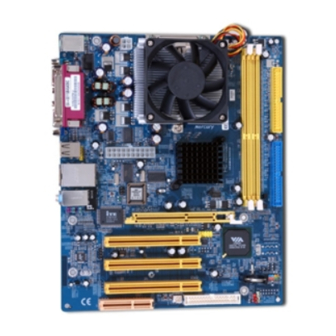
Page 11: Motherboard Components
Motherboard Components Identify major components on the motherboard via this diagram underneath. Note: Any jumpers on your motherboard not appearing in the illustration above are for testing only. -
Page 12: I/O Ports
I/O Ports The illustration below shows a side view of the built-in I/O ports on the motherboard. (optional) (shared with J6) PS/2 Mouse Use the upper PS/2 port to connect a PS/2 pointing device. Use the lower PS/2 port to connect a PS/2 PS/2 Keyboard keyboard. -
Page 13: Installing The Processor
Installing the Processor This motherboard has a Socket 462 processor socket. When choosing a processor, consider the performance requirements of the system. Performance is based on the processor design, the clock speed and system bus frequency of the processor, and the quantity of internal cache memory and external cache memory. -
Page 14: Installing Memory Modules
Installing Memory Modules This motherboard accommodates two 184-pin 2.5V unbuffered Double Data Rate SDRAM (DDR SDRAM) Dual Inline Memory Module (DIMM) sockets, and supports up to 2.0 GB. DDR SDRAM is a type of SDRAM that supports data transfers on both edges of each clock cycle (the rising and falling edges), effectively doubling the memory chip’s data throughput. -
Page 15: Jumper Settings
Jumper Settings Using a jumper cap to connect two pins is SHORT, removing it from these pins, OPEN. CLEAR_CMOS1 CLEAR_CMOS1: Clear CMOS Jumper Use this jumper to clear the contents of the CMOS memory. You may need to clear the CMOS memory if the settings in the Setup Utility are incorrect and prevent your motherboard from operating. -
Page 16: Install The Motherboard
JP3: CPU Clock Selector This jumper selects the processor clock frequency. CPU Clock Pins 1-2 Pins 3-4 133 MHz 166 MHz 100 MHz 200 MHz(KM400A Only) Install the Motherboard Install the motherboard in a system chassis (case). The board is a Micro ATX size motherboard. -
Page 17: Connecting Optional Devices
Here is a list of the PANEL1 pin assignments. Signal Signal: HD_LED_P(+) FP PWR/SLP(+) HD_LED_N(-) FP PWR/SLP(-) RESET_SW_N(-) POWER_SW_P(+) RESET_SW_P(+) POWER_SW_N(-) RSVD_DNU Connecting Optional Devices Refer to the following for information on connecting the motherboard’s optional devices: AUDIO1 SIR1 USB2 SPK1 SPK1: Speaker Header Connect the cable from the PC speaker to the SPK1 header on the... - Page 18 Here is a list of AUDIO1 header pin assignment. Signal Signal AUD_MIC AUD_GND AUD_MIC_BIAS AUD_VCC AUD_FPOUT_R AUD_RET_R HP_ON AUD_FPOUT_L AUD_RET_L USB2: Front Panel USB Header The motherboard has USB ports installed on the rear edge I/O port array. Additionally, some computer cases have USB ports at the front of the case.
-
Page 19: Install Other Devices
Please check the pin assignment of the cable and the USB header on the motherboard. Make sure the pin assignment will match before plugging in. Any incorrect usage may cause unexpected damage to the system. The vendor won’t be responsible for any incidental or consequential damage arising from the usage or misusage of the purchased product. - Page 20 Floppy Disk Drive The motherboard ships with a floppy disk drive cable that can support one or two drives. Drives can be 3.5” or 5.25” wide, with capacities of 360K, 720K, 1.2MB, 1.44MB, or 2.88MB. Install your drives and connect power from the system power supply.
- Page 21 Analog Audio Input Header If you have installed a CD-ROM drive or DVD-ROM drive, you can connect the drive audio cable to the onboard sound system. When you first start up your system, the BIOS should automatically detect your CD-ROM/DVD drive. If it doesn’t, enter the Setup Utility and configure the CD-ROM/DVD drive that you have installed.
-
Page 22: Expansion Slots
Expansion Slots This motherboard has one AGP, one CNR and three 32-bit PCI slots. CNR1 PCI3 PCI2 PCI1 AGP1 Follow the steps below to install an AGP/CNR/PCI expansion card. 1. Locate the AGP, PCI or CNR slot on the motherboard. 2. - Page 23 regarding the specifications of a modem card. You can purchase an approved CNR card in your area and install it directly into the CNR slot.
-
Page 24: Chapter 3: Bios Setup Utility
Chapter 3 BIOS Setup Utility Introduction The BIOS Setup Utility records settings and information about your computer such as the date and time, the kind of hardware installed, and various configuration settings. Your computer uses this information to initialize all the components when booting up and functions as the basis for coordination between system components. -
Page 25: Running The Setup Utility
Running the Setup Utility Each time your computer starts, before the operating system loads, a message appears on the screen that prompts you to “Hit <DEL> if you want to run SETUP”. When you see this message, press the Delete key and the Main menu page of the Setup Utility appears on your monitor. -
Page 26: Standard Cmos Setup Page
Standard CMOS Setup Page This page sets up basic information such as the date, the time, the IDE devices, and the diskette drives. If you press the F3 key, the system will automatically detect and configure the hard disks on the IDE channels. -
Page 27: Advanced Setup Page
Advanced Setup Page This page sets up more advanced information about your system. Take care of this page with more caution. Any changes can affect the operation of your computer. AMIBIOS SETUP – ADVANCED SETUP (C) 2000 American Megatrends, Inc. All Rights Reserved Quick Boot Enabled Boot Device... - Page 28 BootUp Num- This item determines if the Num Lock Lock key is active or inactive at system start- up time. Floppy Drive If you have two diskette drives installed Swap and you enable this item, drive A becomes drive B and drive B becomes drive A.
-
Page 29: Power Management Setup Page
SDRAM CAS# This item determines the operation of Latency SDRAM memory CAS (column address strobe). It is recommended that you leave this item at the default value. The 2T setting requires faster memory that specifically supports this mode. SDRAM Bank Enable this item to increase SDRAM Interleave memory speed. - Page 30 ACPI Aware Enable this item if you are using an O/S that supports ACPI function. Use this item to select a power management Power Management scheme. Both APM and ACPI are supported. Suspend Time This sets the timeout for Suspend mode in minutes.
-
Page 31: Pci/Plug And Play Setup Page
PCI / Plug and Play Setup Page This page sets some of the parameters for devices installed on the PCI bus and devices that use the system plug and play capability. AMIBIOS SETUP – PCI / PLUG AND PLAY SETUP (C) 2000 American Megatrends, Inc. -
Page 32: Load Optimal Settings
Load Optimal Settings If you select this item and press Enter a dialog box appears. If you press Y, and then Enter, the Setup Utility loads a set of fail-safe default values. These default values are not very demanding and they should allow your system to function with most kinds of hardware and memory chips. - Page 33 OnBoard Use these items to enable or disable the Serial PortA onboard COM1 serial port, and to assign a port address. OnBoard IR Use this item to enable or disable the onboard infrared port, and to assign a port address. Port Onboard Use this item to enable or disable the onboard...
-
Page 34: Cpu Pnp Setup Page
CPU PnP Setup Page This page lets you manually configure the motherboard for the CPU. The system will automatically detect the kind of CPU that you have installed and make the appropriate adjustments to the items on this page. AMIBIOS SETUP – CPU PnP SETUP ©2000 American Megatrends, Inc. -
Page 35: Hardware Monitor Page
Hardware Monitor Page This page sets some of the parameters for the hardware monitoring function of this motherboard. AMIBIOS SETUP – HARDWARE MONITOR (C) 2000 American Megatrends, Inc. All Rights Reserved *** System Hardware *** Vcore 1.728V Vdimm 2.592V Vivdd 2.592V Vcc5V 4.865V... -
Page 36: Exit
Change or Remove the Password Highlight this item, press Enter and type in the current password. At the next dialog box, type in the new password, or just press Enter to disable password protection. Exit Highlight this item and press Enter to save the changes that you have made in the Setup Utility configuration and exit the program. -
Page 37: Chapter 4: Software & Applications
Chapter 4 Software & Applications Introduction This chapter describes the contents of the support CD-ROM that comes with the motherboard package. The support CD-ROM contains all useful software, necessary drivers and utility programs to properly run our products. More program information is available in a README file, located in the same directory as the software. -
Page 38: Installing Support Software
Installing Support Software 1.Insert the support CD-ROM disc in the CD-ROM drive. 2.When you insert the CD-ROM disc in the system CD-ROM drive, the CD automatically displays an Auto Setup screen. 3.The screen displays three buttons of Setup, Browse CD and Exit on the right side, and three others Setup, Application and ReadMe at the bottom. - Page 39 Auto-Installing under Windows 2000/XP If you are under Windows 2000/XP, please click the Setup button to run the software auto-installing program while the Auto Setup screen pops out after inserting the support CD-ROM: 1. The installation program loads and displays the following screen.
-
Page 40: Bundled Software Installation
Installing under Windows NT or Manual Installation If you are under Windows NT, the auto-installing program doesn’t work out; or you have to do the manual installation, please follow this procedure while the Auto Setup screen pops out after inserting the support CD-ROM: 1.
Need help?
Do you have a question about the KVM266PM-U Series and is the answer not in the manual?
Questions and answers