Table of Contents
Advertisement
Motherboard User's Guide
This publication, including photographs, illustrations and software,
is under the protection of international copyright laws, with all
rights reserved. Neither this manual, nor any of the material
contained herein, may be reproduced without the express written
consent of the manufacturer.
The information in this document is subject to change without
notice. The manufacturer makes no representations or warranties
with respect to the contents hereof and specifically disclaims any
implied warranties of merchantability or fitness for any particular
purpose. Further, the manufacturer reserves the right to revise this
publication and to make changes from time to time in the content
hereof without obligation of the manufacturer to notify any person
of such revision or changes.
Trademarks
IBM, VGA, and PS/2 are registered trademarks of International
Business Machines.
VIA is a registered trademark of VIA Technologies, Inc.
Microsoft, MS-DOS and Windows 98/ME/NT/2000/XP are
registered trademarks of Microsoft Corporation.
PC-cillin is a trademark of Trend Micro Inc.
AMI is a registered trademark of American Megatrends Inc.
Other names used in this publication may be trademarks and are
acknowledged.
Copyright © 2004
All Rights Reserved
PVCLE266M-L Series,V3.0A
CLE266/May 2004
i
Advertisement
Table of Contents

Related Manuals for Mercury PVCLE266M-L Series


Summary of Contents for Mercury PVCLE266M-L Series
- Page 1 Microsoft Corporation. PC-cillin is a trademark of Trend Micro Inc. AMI is a registered trademark of American Megatrends Inc. Other names used in this publication may be trademarks and are acknowledged. Copyright © 2004 All Rights Reserved PVCLE266M-L Series,V3.0A CLE266/May 2004...
-
Page 2: Table Of Contents
Motherboard User’s Guide Table of Contents Trademark ................... I Static Electricity Precautions ............III Pre-Installation Inspection ..............III Chapter 1: Introduction ............1 Key Features ..................2 Package Contents ................6 Chapter 2: Motherboard Installation ........7 Motherboard Components ..............8 I/O Ports .................... -
Page 3: Static Electricity Precautions
Motherboard User’s Guide Static Electricity Precautions Static electricity could damage components on this motherboard. Take the following precautions while unpacking this motherboard and installing it in a system. 1. Don’t take this motherboard and components out of their original static-proof package until you are ready to install them. - Page 4 Motherboard User’s Guide Notice: 1. Owing to Microsoft’s certifying schedule is various to every supplier, we might have some drivers not certified yet by Microsoft. Therefore, it might happen under Windows XP that a dialogue box (shown as below) pop out warning you this software has not passed Windows Logo testing to verify its compatibility with Windows XP.
-
Page 5: Chapter 1 Introduction
Motherboard User’s Guide Chapter 1 Introduction This motherboard has a VIA C3 CPU onboard with front-side bus speed up to 133MHz. This motherboard integrates the VIA CLE266 Northbridge and 8235 Southbridge chipsets that support DDR 266MHz, Ultra DMA 33/66/100/133 function and remarkably high system performance under all types of system operations It supports built-in USB 2.0 providing higher bandwidth. -
Page 6: Key Features
Motherboard User’s Guide Key Features The key features of this motherboard include: CPU Type • Supports the VIA C3 CPU onboard • Supports 133 MHz Front-Side Bus Chipset There are VIA CLE266 Northbridge and 8235 Southbridge in this chipset in accordance with an innovative and scalable architecture with proven reliability and performance. - Page 7 Chapter 1: Introduction • Universal Serial Bus Controller: USB v2.0 and Enhanced Host Controller Interface (EHCI) v1.0 compatible; USB v1.1 and Universal Host Controller Interface (UHCI) v1.1 compatible Memory Support • Two 184-pin DIMM sockets for DDR memory modules • Supports DDR266/200 memory bus •...
- Page 8 Motherboard User’s Guide • Advanced power management and power saving capabili- ties. • Stereo Line-in function shared with Surround out. • High quality pseudo-differential analog CD Audio input. • Valuable add-on software technology: Support most industry standards of PC 3D sound and unique karaoke function support featured with microphone echo, key shifting, and vocal cancellation.
- Page 9 Chapter 1: Introduction • PCI multi-function device consists of two UHCI Host Controller cores for full-/low-speed signaling and one EHCI Host Controller core for high-speed signaling • Root hub consists 4 downstream facing ports with inte- grated physical layer transceivers shared by UHCI and EHCI Host Controller •...
-
Page 10: Package Contents
Motherboard User’s Guide Package Contents Your motherboard package ships with the following items: • The motherboard • The User Guide • One diskette drive ribbon cable (optional) • One IDE drive ribbon cable • The Software support CD Optional Accessories You can purchase the following optional accessories for this motherboard. -
Page 11: Chapter 2 Motherboard Installation
Chapter 2: Motherboard Installation Chapter 2 Motherboard Installation To install this motherboard in a system, please follow these instructions in this chapter: • Identify the motherboard components • Install a CPU • Install one or more system memory modules • Make sure all jumpers and switches are set correctly •... -
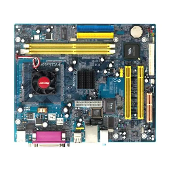
Page 12: Motherboard Components
Motherboard User’s Guide Motherboard Components CPU_FAN1 IDE1 PORTS USB1 IDE2 ATX1 AUDIO2 SPK1 JBAT1 FDC1 PANEL1 CNR1 SYSTEM_FAN1 LABEL COMPONENTS DDR1/2 Two 184-pin DDR SDRAM sockets IDE1/2 Primary/Secondary IDE connectors ATX1 Standard 20-Pin ATX Power connector USB1 Front Panel USB header FDC1 Floppy Disk Drive connector PANEL1... -
Page 13: I/O Ports
Chapter 2: Motherboard Installation LABEL COMPONENTS AUDIO2 Front Panel Audio header USB Card Reader header CPU_FAN1 CPU Fan connector CNR1 Communications Networking Riser slot I/O Ports The illustration below shows a side view of the built-in I/O ports on the motherboard. Optional Shared with J5... -
Page 14: Installing Memory Modules
Motherboard User’s Guide Installing Memory Modules This motherboard accommodates two 184-pin 2.5V DIMM sockets (Dual Inline Memory Module) for unbuffered DDR266/ 200 memory modules (Double Data Rate SDRAM), and maxi- mum 2.0GB installed memory. DDR SDRAM is a type of SDRAM that supports data transfers on both edges of each clock cycle (the rising and falling edges), effectively doubling the memory chip’s data throughput. - Page 15 Chapter 2: Motherboard Installation Align the memory module with the socket. There is a notch on the DIMM socket that you can install the DIMM module in the correct direction. Match the cutout on the DIMM module with the notch on the DIMM socket.
-
Page 16: Jumper Settings
Motherboard User’s Guide Jumper Settings Connecting two pins with a jumper cap is SHORT; removing a jumper cap from these pins, OPEN. JBAT1 JBAT1: Clear CMOS Jumper Use this jumper to clear the contents of the CMOS memory. You may need to clear the CMOS memory if the settings in the Setup Utility are incorrect and prevent your motherboard from operating. -
Page 17: Install The Motherboard
Chapter 2: Motherboard Installation Install the Motherboard Install the motherboard in a system chassis (case). The board is a FLEX ATX size motherboard. You can install this motherboard in an ATX case. Make sure your case has an I/O cover plate matching the ports on this motherboard. -
Page 18: Connecting Optional Devices
Motherboard User’s Guide Here is a list of the PANEL1 pin assignments. Signal Signal 1 HD_LED_P(+) FP PWR/SLP(+) 3 HD_LED_N(-) FP PWR/SLP(-) 5 RESET_SW_N(-) POWER_SW_P(+) 7 RESET_SW_P(+) 8 POWER_SW_N(-) 9 RSVD_DNU 10 KEY Connecting Optional Devices Refer to the following for information on connecting the motherboard’s optional devices: USB1 AUDIO2... - Page 19 Chapter 2: Motherboard Installation AUDIO2: Front Panel Audio Header This header allows the user to install auxiliary front-oriented microphone and line-out ports for easier access. Signal Signal AUD_MIC AUD_GND AUD_MIC_BIAS AUD_VCC AUD_FPOUT_R AUD_RET_R HP_ON AUD_FPOUT_L AUD_RET_L USB1: Front Panel USB Header The motherboard has USB ports installed on the rear edge I/O port array.
- Page 20 Motherboard User’s Guide J5: USB Card Reader Header (optional) This header is for connecting internal USB card reader. You can use a card reader to read or transfer files and digital images to your computer. Signal Signal VCC5 USB - USB+ Note1: The J5 is shared with the lower USB port located beside the VGA port of the I/O back panel.
-
Page 21: Install Other Devices
Chapter 2: Motherboard Installation Install Other Devices Install and connect any other devices in the system. Follow the steps below. IDE1 IDE2 FDC1 Floppy Disk Drive The motherboard ships with a floppy disk drive cable that can support one or two drives. Drives can be 3.5" or 5.25" wide, with capacities of 360K, 720K, 1.2MB, 1.44MB, or 2.88MB. - Page 22 Motherboard User’s Guide The motherboard ships with an IDE cable that can support one or two IDE devices. If you connect two devices to a single cable, you must configure one of the drives as Master and one of the drives as Slave.
-
Page 23: Expansion Slots
Chapter 2: Motherboard Installation When you first start up your system, the BIOS should automati- cally detect your CD-ROM/DVD drive. If it doesn’t, enter the Setup Utility and configure the CD-ROM/DVD drive that you have installed. On the motherboard, locate the 4-pin header CD1. Signal CD IN L CD IN R... - Page 24 Motherboard User’s Guide Install the edge connector of the expansion card into the slot. Ensure the edge connector is correctly seated in the slot. Secure the metal bracket of the card to the system chassis with a screw. CNR Slot You can install the CNR (Communications and Networking Riser) cards in this slot, including LAN, Modem, and Audio functions.
-
Page 25: Chapter 3 Bios Setup Utility
Chapter 3: BIOS Setup Utility Chapter 3 BIOS Setup Utility Introduction The BIOS Setup Utility records settings and information of your computer, such as date and time, the type of hardware installed, and various configuration settings. Your computer applies the information to initialize all the components when booting up and basic functions of coordination between system components. -
Page 26: Running The Setup Utility
Motherboard User’s Guide Running the Setup Utility Every time you start your computer, a message appears on the screen before the operating system loading that prompts you to “Hit <DEL>if you want to run SETUP”. Whenever you see this message, press the Delete key, and the Main menu page of the Setup Utility appears on your monitor. -
Page 27: Standard Cmos Setup Page
Chapter 3: BIOS Setup Utility Standard CMOS Setup Page This page displays a table of items defining basic information about your system. AMIBIOS SETUP – Standard CMOS Setup (C) 2000 American Megatrends, Inc. All Rights Reserved Date (mm/dd/yy): Thu Apr 15,2004 Time (hh/mm/ss): 16:46:44 Blk PIO 32Bit... -
Page 28: Advanced Setup Page
Motherboard User’s Guide Advanced Setup Page This page sets up more advanced information about your system. Handle this page with caution. Any changes can affect the operation of your computer. AMIBIOS SETUP – Advanced Setup (C) 2000 American Megatrends, Inc. All Rights Reserved Quick Boot Enabled Boot Device... - Page 29 Chapter 3: BIOS Setup Utility S.M.A.R.T. for Hard Disks Enable this item if any IDE hard disks support the S.M.A.R.T. (Self-Monitoring, Analysis and Reporting Technology) feature. BootUp Num-Lock This item determines if the Num Lock key is active or inactive at system start-up time. Floppy Drive Swap If you have two diskette drives installed and you enable this item, drive A becomes drive B and drive B becomes drive A.
- Page 30 Motherboard User’s Guide DDR Timing by SPD This item enables or disables the SDRAM timing defined by the Serial Presence Detect electrical. DDR CAS# Latency This item determines the operation of SDRAM memory CAS (column address strobe). It is recommended that you leave this item at the default value.
-
Page 31: Power Management Setup Page
Chapter 3: BIOS Setup Utility Power Management Setup Page This page sets some parameters for system power management operation. AMIBIOS SETUP – Power Management Setup (C) 2000 American Megatrends, Inc. All Rights Reserved ACPI Aware O/S Power Management Enabled Suspend Time Out Disabled LAN/Ring Power On Disabled... - Page 32 Motherboard User’s Guide LAN/Ring Power On The system can be turned off with a software command. If you enable this item, the system can automatically resume if there is an incoming call on the Modem/Ring, or traffic on the network adapter.
-
Page 33: Pci/Plug And Play Setup Page
Motherboard User’s Guide PCI / Plug and Play Setup Page This page sets up some parameters for devices installed on the PCI bus and those utilizing the system plug and play capability. AMIBIOS SETUP – PCI / PLUG AND PLAY SETUP (C) 2000 American Megatrends, Inc. -
Page 34: Load Optimal Settings
Motherboard User’s Guide Load Optimal Settings If you select this item and press Enter a dialog box appears. If you press Y, and then Enter, the Setup Utility loads a set of fail- safe default values. These default values are not very demanding and they should allow your system to function with most kinds of hardware and memory chips. - Page 35 Motherboard User’s Guide OnBoard FDC Use this item to enable or disable the onboard floppy disk drive interface. OnBoard Serial PortA Use this item to enable or disable the onboard COM1 serial port, and to assign a port address. OnBoard Parallel Port This item enables or disables the onboard LPT1 parallel port, and assigns a port address.
-
Page 36: Cpu Pnp Setup Page
Motherboard User’s Guide Audio Device This item enables or disables the AC’ 97 audio chip. Modem Device This item enables or disables the MC’ 97 modem chip.Ethernet Device USB Controller Enable this item to select the USB ports or disable. USB Function for DOS Enable this item if you plan to use the USB ports on this motherboard in a DOS environment. -
Page 37: Hardware Monitor Page
Chapter 3: BIOS Setup Utility Hardware Monitor Page This page sets up some parameters for the hardware monitoring function of this mainboard. AMIBIOS SETUP – Hardware Monitor (C) 2000 American Megatrends, Inc. All Rights Reserved *** System Hardware *** CPU Vcore 1.616 V Vcc2.5V 2.432 V... -
Page 38: Change Password
Motherboard User’s Guide Change Password If you highlight this item and press Enter, a dialog box appears that you can enter a Supervisor password. You can enter no more than six letters or numbers. Press Enter after you have typed in the password. -
Page 39: Chapter 4 Software & Applications
Chapter 4: Software & Applications Chapter 4 Software & Applications Introduction This chapter describes the contents of the support CD-ROM that comes with the motherboard package. The support CD-ROM contains all useful software, necessary drivers and utility programs to properly run our products. More program information is available in a README file, located in the same directory as the software. -
Page 40: Installing Support Software
Motherboard User’s Guide Installing Support Software Insert the support CD-ROM disc in the CD-ROM drive. When you insert the CD-ROM disc in the system CD- ROM drive, the CD automatically displays an Auto Setup screen. The screen displays three buttons of Setup, Browse CD and Exit on the right side, and three others Setup, Application and ReadMe at the bottom. - Page 41 Chapter 4: Software & Applications Auto-Installing under Windows 98/ME/2000/XP If you are under Windows 98/ME/2000/XP, please click the Setup button to run the software auto-installing program while the Auto Setup screen pops out after inserting the support CD-ROM: The installation program loads and displays the following screen.
-
Page 42: Bundled Software Installation
Motherboard User’s Guide Installing under Windows NT or Manual Installation If you are under Windows NT, the auto-installing program doesn’t work out; or you have to do the manual installation, please follow this procedure while the Auto Setup screen pops out after insert- ing the support CD-ROM: Click the ReadMe to bring up a screen, and then click the Install Path at the bottom of the screen.
Need help?
Do you have a question about the PVCLE266M-L Series and is the answer not in the manual?
Questions and answers