Table of Contents
Advertisement
Quick Links
Advertisement
Table of Contents

Related Manuals for Planet FGSW-1602


Summary of Contents for Planet FGSW-1602
- Page 1 10/100/1000Mbps Ethernet Switch FGSW-1602 User’s Guide...
-
Page 2: Fcc Information
FCC Information The Federal Communication Commission Radio Frequency Interference Statement includes the following paragraph: This equipment has been tested and found to comply with the limits for a Class B Digital Device, pursuant to Part 15 of the FCC Rules. These limits are designed to provide reasonable protection against harmful interference in a residential installation. This equipment generates, uses and can radiate radio frequency energy and, if not installed and used in accordance with the instructions, may cause harmful interference to radio communication. - Page 3 Limited Warranty In no event will Planet be liable for any damage, including loss of data or profits, cost of cover, or other incidental, consequential or indirect damages arising from the installation, maintenance, use, performance, failure or interruption of Planet’s products, whatever caused and on any theory of liability.
-
Page 4: Table Of Contents
CONTENTS Chapter 1 Introduction Fast Ethernet Technology Fast Ethernet Hub Technology Dual-Speed Ethernet Hub Technology Switching Technology Gigabit Technology Chapter 2 About Ethernet Switch Package Contents Device Description, Features and Capabilities Chapter 3 Planning your Network 10Base-T Ethernet Network Guidelines 100Base-TX Ethernet Network Guidelines 100BASE-FX Network Guidelines 1000BASE-SX and LX Network Guideline... -
Page 5: Chapter 1 Introduction
Chapter 1 Introduction This section provides you with useful Fast Ethernet, hub and switching technology background. Fast Ethernet Technology In July 1993, the Fast Ethernet Alliance was formed by a group of networking companies with the goal of drafting the 802.3u 100BaseT specifications of the Institute of Electrical and Electronics Engineers (IEEE). -
Page 6: Fast Ethernet Hub Technology
Fast Ethernet Hub Technology Class I Fast Ethernet Hubs Class I hubs must be used when connecting differing network media such as two wire-pair 100BASE-TX media with four wire- pair 100BASE-T4 media within the same collision domain. The hub receives line data from any port, translates it into a digital signal, retranslates the signal back into the appropriate line data and repeats it to all other ports. -
Page 7: Gigabit Technology
stackable hubs to increase the total number ports within each collision domain. A switch uses store and forwarding technology to transfer data between collision domains at the MAC address level of the Ethernet protocol. This means that data is transferred only to the data’s destination collision domain. The data is not transferred to other collision domains, which allows your total LAN capacity to be increased without the need to invest in new media infrastructure. -
Page 8: Chapter 2 About Ethernet Switch
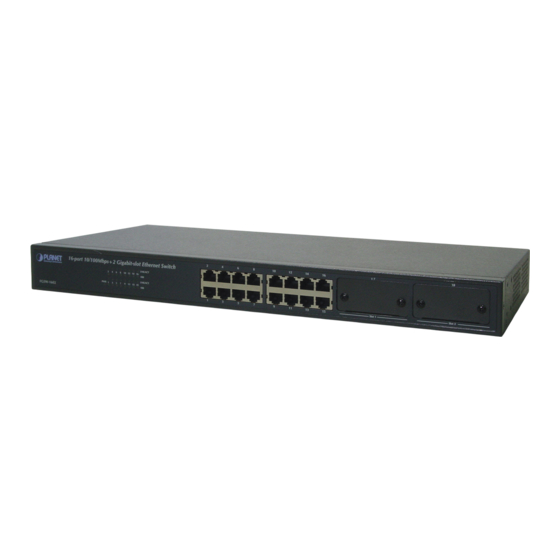
Chapter 2 About Ethernet Switch The Ethernet Switchs are multi-speed network devices combining Ethernet, Fast Ethernet and Gigabit Ethernet capabilities in a single compact, rack-mountable cabinet. Combining 10Mbps Ethernet, 100Mbps Fast Ethernet and Gigabit Ethernet interfaces in one unit allows these switches to unclog existing LANs and provide a path to efficient, high-speed networking. The Ethernet Switch provides 16 10/100Base-TX ports, plus 2 slots for 3 optional different slide-in modules. - Page 9 Figure 2-3. Rear Panel All LED status indicators are located on the FRONT panel of the switches. They provide a real-time indication of system and operational status. The ports for connections to other devices and networks are also on the front panels, along with the crossover switches.
- Page 10 8 ports 10/100Base-TX Module – FGSW-8TP When installed into a Ethernet Switch, the 10/100Base-TX Module provides 8 10/100Mbps Switch ports which can connect the Switch to a 10Mbps or 100Mbps hub or end station. (1). 8 Ports 10/100Base-Tx Module Features ♦...
- Page 11 ♦ Connect the Switch to a 100Mbps server or end-station An ST (or SC) connector provides the link to the multi-mode fiber cabling and two indicators show the status of the Module at-a glance. A DIP-switch sets the operating mode to half duplex or full duplex (default). DIP Switch Location Port 1 Port 2...
- Page 12 Four Ports 100Base-FX Fiber Module – FGSW-4ST/4SC Figure 2-7. 4 port 100Base-TX/FX Front View When installed into a Ethernet Switch, this Module provides 4 x 100Mbps Fast Ethernet fiber ports which can be used to: ♦ Connect the Switch to the backbone of your network; that is, to a basement switch, hub or router. ♦...
- Page 13 (1) 1000Base-SX/LX Fiber Module Features ♦ Conforms to IEEE 802.3z draft 4.2 and 802.3x standard ♦ 1x1000Base-SX/LX Ethernet Port ♦ 3M memory buffer support ♦ Standard auto-negotiation for speed, duplex mode and flow-control for MII and GMII PHYs ♦ Backpressure option and Limit4 option for half duplex ♦...
-
Page 14: Chapter 3 Planning Your Network
Chapter 3 Planning your Network Before you install your Switch, you should review the guidelines for setting up Ethernet networks. Further, you should plan your network to take maximum advantage of its switching capabilities. 10Base-T Ethernet Network Guidelines ♦ The maximum length of a 10Base-T cable segment is 100 meters (328 feet). ♦... -
Page 15: Collapsed Backbone Link
Figure 3-1. Expanding your 10Base-T Network 100Base-TX Networks The hub limit of a 100Base-TX network depends on the class of the hub in the network. With a Class I hub, the network is limited to one hub. With a Class II hub, the network is limited to two hubs. However, you can expand your 100Base-TX network that includes either class of hub by adding a Switch. -
Page 16: Fileserver Link
Figure 3-3. Switch 100/1000 Hub in a collapsed backbone link File server Link 100Base Solution With a fileserver link, you can increase file server performance by increasing the Hub's bandwidth between one or more fileservers and the workgroups they serve. If you connect 10Mbps workgroup hubs to the 10Mbps ports on the Switch, traffic in one workgroup will not interfere with the performance of another workgroup. -
Page 17: Multiport Bridge With High-Bandwidth Backbone
increases to beyond the performance of standard 10Base-T or 100Base-TX hubs. Operating the Switch at full duplex further increases performance 1000Base Solution You can upgrade your server with a Gigabit Ethernet NIC, and introduce a Gigabit backbone switch too. This contain several switch ports which provides much faster access to your server with minimum disruption. -
Page 18: Chapter 4 Installation
Chapter 4 Installation The Ethernet Switch can be installed quickly and easily. However, for an installation with minimum impact on the existing network, please read this chapter carefully. Installing a Ethernet Switch involves three steps: 1. Choosing a location 2. Supplying power 3. -
Page 19: Connecting The Switch
Connecting the Switch You can connect your switch to network devices such as desktops and workgroups or to other hubs. Before connecting your switch to a desktop or workgroup make sure that: The 10Base-T twisted pair Ethernet cabling is Category 3 or above. The 100Base-TX Fast Ethernet cabling is tested Category 5. -
Page 20: Chapter 5 Module Installation And Removal
Chapter 5 Module Installation and Removal WARNING: Before installing the Modules into a Switch, you must disconnect the Switch from the main power supply. Handling the Modules The Module can be easily damaged by electrostatic discharge. To prevent damage, please observe the following: Do not remove Modules from their packaging until you are ready to install it into a Switch. -
Page 21: Removing The Modules
Check the LED indicators on the front of the Switch to ensure that the Module is operating correctly. Removing the Modules a. Ensure that the power supply and the backbone connection cables are disconnected from the Switch. b. Place the Switch on a flat surface. Undo the two captive thumbscrews securing the Module into the Switch. Do not remove any other screws from the rear of the Switch. -
Page 22: Appendix A Technical Specifications
Appendix A Technical Specifications Compatibility with Ethernet Standards The FGSW switches have been designed in accordance with IEEE Standard 802.3 and 802.3u and 802.3z. Power Input: Voltage Frequency 100V AC to 240V AC 50Hz to 60Hz Environment: Operating Storage 0 ¢ J to 55 ¢ J -20 ¢... -
Page 23: Pin Assignments
Appendix B Pin Assignments Hub's Station Ports (MDI- Uplink Port (MDI-II port) X port) Input Receive Data + Output Transmit Data+ Input Receive Data - Output Transmit Data- Output Transmit Data+ Input Receive Data + Output Transmit Data- Input Receive Data - 4,5,7,8 Not used Not used...
Need help?
Do you have a question about the FGSW-1602 and is the answer not in the manual?
Questions and answers