
Related Manuals for Planet FGSW-1822VHP


Summary of Contents for Planet FGSW-1822VHP
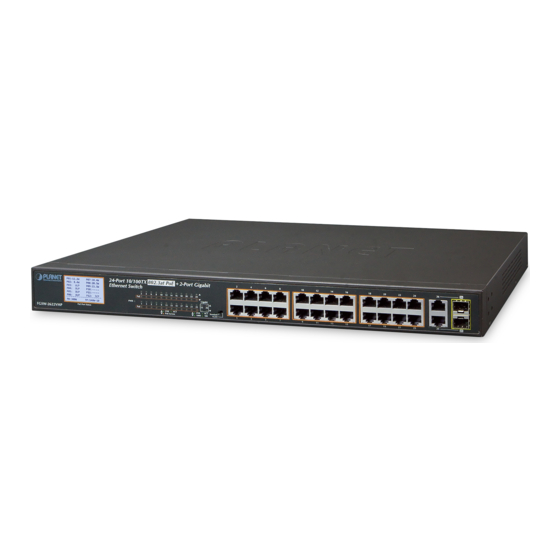
- Page 1 16-/24-Port 10/100TX 802.3at PoE + 2-Port Gigabit TP + 2-Port SFP Ethernet Switch with LCD PoE Monitor FGSW-1822VHP/FGSW-2622VHP User’s Manual...
- Page 2 Copyright Copyright © 2017 by PLANET Technology Corp. All rights reserved. No part of this publication may be re-produced, transmitted, transcribed, stored in a retrieval system, or translated into any language or computer language, in any form or by any means, electronic, mechanical, magnetic, optical, chemical, manual or oth- erwise, without the prior written permission of PLANET.
- Page 3 WEEE as unsorted mu-nicipal waste; WEEE should be collected separately. Revision PLANET 16-/24-Port 10/100TX 802.3at PoE + 2-Port Gigabit TP + 2-Port SFP Ethernet Switch with LCD PoE Monitor User's Manual Models: FGSW-1822VHP, FGSW-2622VHP Revision: 2.0 (Nov., 2017)
-
Page 4: Table Of Contents
Table of Contents 1. Introduction ....................5 1.1 Package Contents ................5 1.2 Product Description ................6 1.3 Features ....................10 1.4 Specifications ..................12 2. Hardware Description .................14 2.1 Front Panel ..................14 2.1.1 LCD Monitor Indicators ..............15 2.1.2 LED Indicators ................16 2.2 Rear Panel ..................17 2.3 LCD Management ................18 2.3.1 Switch Mode ................19... -
Page 5: Introduction
1. Introduction Thank you for purchasing PLANET 16-/24-Port 10/100TX 802.3at PoE + 2-Port Gigabit TP + 2-Port SFP Ethernet Switch series, FGSW-1822VHP and FGSW- 2622VHP. The descriptions of these models are shown below: 16-Port 10/100TX 802.3at PoE + 2-Port Gigabit TP + 2-Port... -
Page 6: Product Description
Ideal High-performance Integration Solution for Secure IP Surveillance Infrastructure Particularly designed for the IP surveillance applications, PLANET FGSW 802.3at PoE+ Switch series is perfect for the installation of IP cameras in a remote site, where its power allocation can be centrally managed. - Page 7 Simple “Plug and Watch” for a Quick Solution PLANET FGSW-1822VHP is an ideal Plug and Watch Power over Ethernet solution which provides quick installation, real-time PoE work status monitoring and immediate troubleshooting through its unique LCD display to improve work efficiency and quality without any PC or software required.
- Page 8 Smart and Intuitive LCD Control PLANET FGSW 802.3at PoE+ Switch series provides an intuitive color panel on its front panel that facilitates the Ethernet management and PoE PD management. They greatly promote management efficiency in large-scale network, such as enterprises, hotels, shopping malls, government buildings, and other public areas, and feature the following special management and status functions: „...
- Page 9 Standard, VLAN and Extend Operation Modes Offered PLANET FGSW 802.3at PoE+ Switch series provides Standard, VLAN and Extend operation modes. The FGSW 802.3at PoE+ Switch series operates as a normal IEEE 802.at/af PoE Switch in the Standard operation mode. The VLAN operation mode features the port-based VLAN function that can help to prevent the IP camera’s multicast or broadcast storm from influencing each other.
-
Page 10: Features
Flexible Extension Solution PLANET FGSW 802.3at PoE+ Switch series provides 2 extra Gigabit TP and 2 SFP interfaces supporting 10/100/1000BASE-T RJ45 copper for surveillance network devices such as NVR, video streaming server or NAS to facilitate surveillance management. Or through these Gigabit speed fiber SFP slots, the 1000BASE-SX/LX SFP (Small Form-factor Pluggable) fiber transceiver is inserted to be uplinked to a backbone switch and monitoring center over a long distance. - Page 11 „ Up to 16/24 ports of IEEE 802.3af/at devices powered „ Supports PoE Power up to 32 watts for each PoE port „ Each port supports 54V DC power to PoE Powered Device „ 300-watt PoE budget „ Auto detects powered device (PD) „...
-
Page 12: Specifications
„ Supports Energy-Efficient Ethernet (EEE) function (IEEE 802.3az) „ Supports contact discharge of ±6KV DC and air discharge of ±8KV DC for Ethernet ESD protection „ Supports ±6KV surge immunity 1.4 Specifications Model FGSW-1822VHP FGSW-2622VHP Hardware Specifications 802.3af/at PoE Injector Port 10/100BASE-TX MDI/MDIX Ports... - Page 13 Enclosure Metal Weight 3.3kg 3.4kg Power Requirements 100~240V AC, 50/60Hz, 5A max. Power Consumption/Dissipation Max. 330watts/1132 BTU Thermal Fan Contact discharge of ±6KV DC ESD Protection Air discharge of ±8KV DC Surge Protection ±6KV Power over Ethernet IEEE 802.3af Power over Ethernet/PSE PoE Standard IEEE 802.3at Power over Ethernet Plus/PSE PoE Power Supply Type...
-
Page 14: Hardware Description
From 550 meters (multi-mode fiber) to 10/20/30/40/50/60/70/120 kilo- meters (single-mode fiber). „ Smart LCD The Smart LCD that is located on the front panel of the FGSW-1822VHP, FGSW- 2622VHP 802.3at PoE+ Switch provides “PoE Management and Status”, “Switch Mode: Standard, VLAN, Extend”, “Budget and Bandwidth... -
Page 15: Lcd Monitor Indicators
Power Low-voltage Protection Power Over-voltage Protection PSE Over-temperature Protection 1. The LCD screens of the FGSW-1822VHP and FGSW-2622VHP are the same, except the number of ports and port allocation. 2. The LCD screens of the FGSW-1822VHP and FGSW-2622VHP will refresh every 15 seconds. -
Page 16: Led Indicators
Parameters Description It means the port corresponding to the PSE is lightly loaded and the port stops powering (When the current on the network is less than 7.5mA, the PSE thinks the PD has been dialed out and the port stops powering). It means the port corresponding to the PSE appears to be short-circuited and the port stops powering. -
Page 17: Rear Panel
The rear panel of the 802.3at PoE+ Switch has an AC power socket (100 to 240V AC, 50-60Hz, 5A). 100~240V AC 50/60Hz, 5A max. Figure 2-3: FGSW-1822VHP/FGSW-2622VHP Switch Rear Panel „ AC Power Receptacle For compatibility with electrical outlet standard in most areas of the world, the 802.3at PoE+ Switch’s power supply automatically adjusts to line power in the... -
Page 18: Lcd Management
2.3 LCD Management The operation of the 5 buttons (Menu, Enter, Back, Up and Down) on the panel: Switch Port Information Menu (5 sec) 30.3 W ---M -33M ---- W ---M ---M ---- W ---M ---M -8.3 W ---M -11M ----W ---M ---M ----... -
Page 19: Switch Mode
2.3.1 Switch Mode There are three modes -- “Standard”, “VLAN” and “Extend” – for selection. Model FGSW-1822VHP FGSW-2622VHP Switch Mode Function This mode makes the 802.3at PoE+ Switch operate as a Standard general switch and all PoE ports operate at 10/100Mbps auto- (default) negotiation. - Page 20 Ports 1 to 16 Ports 17 and 18 IP Camera Access Denied 1000 Ports 1~16 Access Permitted Standard VLAN < Extend IP Camera FGSW-1822VHP 1000BASE-SX/LX Fiber-optic 100BASE-TX UTP with PoE 1000 100BASE-TX UTP Standard Mode (default) Standard < PoE IP Camera VLAN Extend...
-
Page 21: Budget Control
2.3.2 Budget Control Due to the power allocation strategy of PSE, when the residual power of PoE is too large, the power distribution of the port can be increased as much as possible by increasing the power trimming of the PSE, so that the utilization of the PSE power supply can be improved. -
Page 22: Pse Port Enable
2.3.4 PSE Port Enable Allows user to disable or enable per port PoE function. The default is “Enable”. 2.3.5 PD Type Changing the PoE power-up mode can let non-standard PDs pass the procedures of PoE power delivery process. This way, the switch can supply power to non- standard PDs. -
Page 23: Alive Check
2.3.6 Alive Check The FGSW 802.3at PoE+ Switch series can be configured to monitor connected PD’s status in realtime via traffic detection. Once there is no traffic at interval time, the FGSW 802.3at PoE+ Switch series is going to restart PoE port power, and bring the PD back to work. -
Page 24: Bandwidth Detection
The PD Alive Check is not a defining standard, so the PoE device on the market doesn’t report reboots done information to the PoE Switch. So user has to make sure how long it takes for the PD to finish booting, and then set the time value related column. -
Page 25: Screen Saver
2.3.9 Screen Saver There are four levels of budget control, namely Always ON, 10min (default), 20min and 30min. 2.3.10 Language There are two languages, namely English and Chinese. -
Page 26: Default Setting
2.3.11 Default Setting Press “Yes” to reset to default. 2.3.12 System Show the system information. -
Page 27: Hardware Installation
3. Hardware Installation Start up Please refer to the following for your cabling: 10/100BASE-TX All 10/100BASE-TX ports come with Auto-Negotiation capability. They automatically support 100BASE-TX and 10BASE-T networks. Users only need to plug a working network device into one of the 10/100BASE-TX ports, and then turn on the 802.3at PoE+ Switch. -
Page 28: Desktop Installation
3.1 Desktop Installation To install the 802.3at PoE+ Switch on desktop, simply follow the following steps: Step 1: Attach the rubber feet to the recessed areas on the bottom of the 802.3at PoE+ Ethernet Switch, as shown in Figure 3-1. Men u (5 sec) Ente r... -
Page 29: Rack Mounting
3.2 Rack Mounting To install the 802.3at PoE+ Switch in a 19-inch standard rack, follow the instructions described below. Step 1: Place your 802.3at PoE+ Switch on a hard flat surface, with the front panel positioned towards your front side. Step 2: Attach a rack-mount bracket to each side of the 802.3at PoE+ Switch with supplied screws attached to the package. -
Page 30: Installing The Sfp Transceiver
Figure 3-4: Plug In the SFP Transceiver „ Approved PLANET SFP Transceivers PLANET 802.3at PoE+ Switch supports both single mode and multi-mode SFP transceivers. The following list of approved PLANET SFP transceivers is correct at the time of publication: Gigabit SFP Transceiver Modules „... - Page 31 It is recommended to use PLANET SFP on the 802.3at PoE+ Switch. If you insert an SFP transceiver that is not supported, the 802.3at PoE+ Switch will not recognize it. Note 1. Before we connect the 802.3at PoE+ Switch to the other network device, we have to make sure both sides of the SFP transceivers are with the same media type, for example, 1000BASE-SX to 1000BASE-SX;...
-
Page 32: Product Applications
AP group for enterprises. Cameras can be installed around the corner in the company or campus for surveillance demands. Without the power-socket limitation, the 802.3at PoE+ Switch makes the installation of cameras easier and more efficient. PC Group PoE IP FGSW-1822VHP Camera 1000 PoE Wireless AP Laptop Core Switch 802.3af Splitter... -
Page 33: Power Over Ethernet Powered Devices
3.5 Power over Ethernet Powered Devices Voice over IP Phones As many as PoE VoIP phones, ATAs and other Ethernet/ non-Ethernet end-devices can be installed, but UPS is needed for uninterrupted power system and power control 3~5 watts system. Wireless LAN Access Points Access points can readily be installed in museums, sightseeing sites, airports, hotels, campuses, factories and warehouses. -
Page 34: Power Over Ethernet Overview
4. Power over Ethernet Overview What is PoE? PoE is an abbreviation of Power over Ethernet. The PoE technology means a system safely transmits both power and data on Ethernet UTP cable. The IEEE standard for PoE technology requires Category 5 cable or higher for high power PoE levels, but can operate with Cat3 cable for low power levels. - Page 35 intermediary device between a non-PoE capable switch and a PoE device, it is called a mid-span. An external PoE injector is a mid-span device. Powered Device A powered device (PD) is a device powered by a PSE and thus consumes energy. Examples include wireless access points, IP phones, and IP cameras.
- Page 36 The data pairs are used. Since Ethernet pairs are transformers coupled at each end, it is possible to apply DC power to the center tap of the isolated transformer without upsetting the data transfer. In this mode of operation, the pair on pins 3 and 6 and the pair on pins 1 and 2 can be of either polarity.
-
Page 37: Troubleshooting
Solution: 1. Please check the cable type of the connection from FGSW-1822VHP/FGSW- 2622VHP to the other end. The cable should be an 8-wire UTP, Category 5 or above and EIA568 cable within 100 meters. A cable with only 4-wire, short loop or over 100 meters will affect the power supply. -
Page 38: Appendix A Networking Connection
Appendix A Networking Connection A.1 Switch’s Data RJ45 Pin Assignments - 1000Mbps, 1000BASE-T PIN NO MDI-X BI_DA+ BI_DB+ BI_DA- BI_DB- BI_DB+ BI_DA+ BI_DC+ BI_DD+ BI_DC- BI_DD- BI_DB- BI_DA- BI_DD+ BI_DC+ BI_DD- BI_DC- Implicit implementation of the crossover function within a twisted-pair cable, or at a wiring panel, while not expressly forbidden, is beyond the scope of this standard. - Page 39 The standard cable, RJ45 pin assignment The standard RJ45 receptacle/connector There are 8 wires on a standard UTP/STP cable and each wire is color-coded. The following shows the pin allocation and color of straight-through cable and crossover cable connection: Straight Cable SIDE 1 SIDE 2 1 = White/Orange...
- Page 40 : FGSW -1822VHP/FGSW-2622VHP * Produced by: Manufacturer's Name : Planet Technology Corp. Manufacturer's Address : 10F., No.96, Minquan Rd., Xindian Dist., New Taipei City 231, Taiwan (R.O.C.). is herewith confirmed to comply with the requirements set out in the Council Directive on the Approximation of the Laws of the Member States relating to Electromagnetic Compatibility Directive on (2014/30/EU) and Low Voltage Directive 2014/35/EU.
Need help?
Do you have a question about the FGSW-1822VHP and is the answer not in the manual?
Questions and answers