
Related Manuals for Planet FGSD-1022VHP


Summary of Contents for Planet FGSD-1022VHP
- Page 1 8/16/24-Port 10/100TX 802.3at PoE + 2-Port Gigabit TP/SFP Combo Ethernet Switch FGSD-1022VHP/FGSW-1822VHP/FGSW-2622VHP User’s Manual...
-
Page 2: Fcc Warning
Disclaimer PLANET Technology does not warrant that the hardware will work properly in all environments and applications, and makes no warranty and representation, either implied or expressed, with respect to the quality, performance, merchantability, or fitness for a particular purpose. - Page 3 Do not dispose of WEEE as unsorted municipal waste and have to collect such WEEE separately. Revision PLANET 8/16/24-Port 10/100TX 802.3at PoE+ 2-Port Gigabit TP/SFP Combo Ethernet Switch User’s Manual Models: FGSD-1022VHP, FGSW-1822VHP, FGSW-2622VHP Revision: 1.0 (January, 2016)
-
Page 4: Table Of Contents
Table of Contents 1. Introduction ....................5 1.1 Package Contents ................5 1.2 Product Description ................6 1.3 Features ..................... 8 1.4 Specifications ..................10 2. Hardware Description .................12 2.1 Front Panel ..................12 2.1.1 LCD Monitor Indicators ..............15 2.1.2 LED Indicators ................17 2.2 Rear Panel ..................18 3. -
Page 5: Introduction
1. Introduction Thank you for purchasing PLANET 8/16/24-Port 10/100TX 802.3at PoE+ 2-Port Gigabit TP/SFP Combo Ethernet Switch series, FGSD-1022VHP, FGSW-1822VHP and FGSW-2622VHP. The descriptions of these models are shown below: 8-Port 10/100TX 802.3at PoE + 2-Port Gigabit TP/SFP Combo FGSD-1022VHP Desktop Switch 16-Port 10/100TX 802.3at PoE + 2-Port Gigabit TP/SFP Combo... -
Page 6: Product Description
1.2 Product Description Ideal Cost-effective Integration Solution for Secure IP Surveillance Infrastructure Particularly designed for the growing popular IP surveillance applications, PLANET FGSD/FGSW 802.3at PoE+ Switch series is positioned as a surveillance switch with the central power management and IP camera monitoring. - Page 7 LCD Monitor for Real-time PoE Usage and System Status Display The LCD monitor of the FGSD/FGSW 802.3at PoE+ Switch series clearly shows the levels of PoE power usage and system status, such as overload, low voltage, over voltage and high temperature. With its brand-new LCD monitor, user is able to obtain detailed information about real-time PoE power usage and real-time system status of the FGSD/FGSW 802.3at PoE+ Switch series.
-
Page 8: Features
„ Up to 8/16/24 ports of IEEE 802.3af/802.3at devices powered „ Supports PoE Power up to 30.8 watts for each PoE port „ Each port supports 53V DC power to PoE Powered Device (FGSD-1022VHP) „ 120-watt PoE budget (FGSD-1022VHP) „ Each port supports 54V DC power to PoE Powered Device (FGSW-1822VHP or FGSW-2622VHP) „... - Page 9 „ LED indicators for system power, per port PoE ready and PoE activity, speed, Link/Act „ LCD Monitor for system status and PoE usage status display „ 1 silent fan to provide stable and efficient power performance (FGSD-1022VHP) „ 2 silent fans to provide stable and efficient power performance (FGSW-1822VHP or FGSW-2622VHP)
-
Page 10: Specifications
1.4 Specifications Model FGSD-1022VHP FGSW-1822VHP FGSW-2622VHP Hardware Specifications 802.3af/802.3at PoE Injector Port 10/100BASE-TX MDI/ MDIX Ports 10/100/1000BASE-T MDI/ 2 (Combo Port) MDIX Ports 1000BASE-X SFP/mini-GBIC 2 (Combo Port) Slots DIP Switch Switch Architecture Store-and-Forward 5.6Gbps/ 7.2Gbps/ 8.8Gbps/ Switch Fabric non-blocking... - Page 11 Power Consumption/ Max. 130 Max. 330 watts/1125 BTU Dissipation watts/443 BTU Thermal Fan Power over Ethernet IEEE 802.3af Power over Ethernet/PSE PoE Standard IEEE 802.3at Power over Ethernet Plus/PSE PoE Power Supply Type End-span Per port 53V-54V DC, 300mA. max. 15.4 watts (IEEE 802.3af) PoE Power Output Per port 53V-54V DC, 600mA.
-
Page 12: Hardware Description
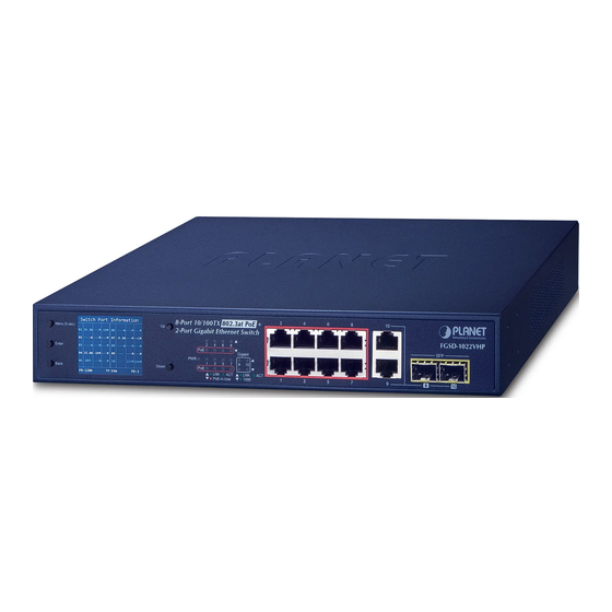
2-Port Gigabit Desktop Switch FGSD-1022VHP Mini-GBIC Gigabit PoE Port Status Standard VLAN PoE In-Use 1000 Extend Figure 2-1: FGSD-1022VHP Switch Front Panel 16-Port 10/100TX 802.3at PoE + 2-Port Gigabit Ethernet Switch 1000 PoE Port Status FGSW-1822VHP Gigabit Standard PoE In-Use... - Page 13 (single-mode fiber). „ DIP Switch The DIP switch that is located on the front panel of the FGSD-1022VHP 802.3at PoE+ Switch provides “Standard”, “VLAN” and “Extend” mode selection; the “Extend” mode features 30-watt PoE transmit distance of 250m at speed of 10Mbps.
- Page 14 Default PoE Mode PoE IP Camera Standard VLAN FGSD-1022VHP Extend Power 100 meters(328 feet) VLAN Isolation Mode IP Camera Port 9 and Port 10 Port 1 and Port 8 IP Camera Permit Access Denied Standard VLAN Extend IP Camera FGSD-1022VHP...
-
Page 15: Lcd Monitor Indicators
8-Port 10/100TX 802.3at PoE 2-Port Gigabit Desktop Switch FGSD-1022VHP Mini-GBIC Gigabit PoE Port Status Standard VLAN PoE In-Use 1000 Extend uplink 8-Port 10/100TX 802.3at PoE 2-Port Gigabit Desktop Switch FGSD-1022VHP Mini-GBIC Gigabit PoE Port Status Standard VLAN PoE In-Use 1000... - Page 16 1. The LCD Monitor screen of FGSW-1822VHP and FGSW-2622VHP is the same, except the port numbers and port allocation. 2. The LCD Monitor screen of FGSW-1822VHP and FGSW-2622VHP Note will refresh every 10 seconds. The detailed description of each item is shown below: OLP: It means Over Load Protect.
-
Page 17: Led Indicators
2.1.2 LED Indicators „ System Color Function Green Lights to indicate that the Switch has power. „ Per 10/100Mbps Port with PoE Interfaces Color Function Indicates the link through that port is Lights: successfully established at 10/100Mbps. LNK/ACT Green Indicates that the Switch is actively sending or Blinks: receiving data over that port. -
Page 18: Rear Panel
The rear panel of the 802.3at PoE+ Switch indicates an AC power socket, which accepts input power from 100 to 240V AC, 50-60Hz, 2.5A/5A. 100-240V AC 50/60Hz, 2.5A Figure 2-4: FGSD-1022VHP Switch Rear Panel 100~240V AC 50/60Hz, 5A max. Figure 2-5: FGSW-1822VHP/FGSW-2622VHP Switch Rear Panel AC Power Receptacle For compatibility with electrical outlet standard in most areas of the world, the 802.3at PoE+ Switch’s power supply automatically adjusts to line power in the... -
Page 19: Hardware Installation
3. Hardware Installation Start up Please refer to the following for your cabling: 10/100BASE-TX All 10/100BASE-TX ports come with Auto-Negotiation capability. They automatically support 100BASE-TX and 10BASE-T networks. Users only need to plug a working network device into one of the 10/100BASE-TX ports, and then turn on the 802.3at PoE+ Switch. -
Page 20: Desktop Installation
3.1 Desktop Installation To install the 802.3at PoE+ Switch on desktop, simply follow the following steps: Step 1: Attach the rubber feet to the recessed areas on the bottom of the 802.3at PoE+ Ethernet Switch, as shown in Figure 3-1. Figure 3-1: Attaching the Rubber Feet to the 802.3at PoE+ Switch Step 2: Place the 802.3at PoE+ Switch on desktop near an AC power source. -
Page 21: Rack Mounting
Step 5: Supply power to the 802.3at PoE+ Switch. A. Connect one end of the power cable to the 802.3at PoE+ Switch. B. Connect the power plug of the power cable to a standard wall outlet. When the 802.3at PoE+ Switch receives power, the Power LED should remain solid Green. -
Page 22: Installing The Sfp Transceiver
Step 5: After the brackets are attached to the 802.3at PoE+ Switch, use suitable screws to securely attach the brackets to the rack, as shown in Figure 3-3. Figure 3-3: Mounting the 802.3at PoE+ Switch in a Rack Step 6: Proceed with Steps 4 and 5 of session 3.1 Desktop Installation to connect the network cabling and supply power to your Switch. - Page 23 Approved PLANET SFP Transceivers PLANET 802.3at PoE+ Switch supports both single mode and multi-mode SFP transceivers. The following list of approved PLANET SFP transceivers is correct at the time of publication: Gigabit SFP Transceiver Modules MGB-GT SFP-Port 1000BASE-T Module ...
- Page 24 Connect the Fiber Cable 1. Insert the duplex LC connector into the SFP transceiver. 2. Connect the other end of the cable to a device with SFP transceiver installed. 3. Check the LNK/ACT LED of the SFP slot on the front of the 802.3at PoE+ Switch.
-
Page 25: Product Applications
3.4 Product Applications Department/Workgroup PoE Switch: Providing 8/16/24 PoE in-line power interfaces, the 802.3at PoE+ Switch can easily build a power that centrally controls IP phone system, IP camera system and wireless AP group for enterprises. Cameras can be installed around the corner in the company or campus for surveillance demands. -
Page 26: Power Over Ethernet Powered Devices
3.5 Power over Ethernet Powered Devices Voice over IP Phones As many as PoE VoIP phones, ATAs and other Ethernet/ non-Ethernet end-devices can be installed, but UPS is needed for uninterrupted power system and power control 3~5 watts system. Wireless LAN Access Points Access points can readily be installed in museums, sightseeing sites, airports, hotels, campuses, factories and warehouses. -
Page 27: Power Over Ethernet Overview
4. Power over Ethernet Overview What is PoE? PoE is an abbreviation of Power over Ethernet. The PoE technology means a system safely transmits both power and data on Ethernet UTP cable. The IEEE standard for PoE technology requires Category 5 cable or higher for high power PoE levels, but can operate with Cat3 cable for low power levels. - Page 28 end-span (although IEEE 802.3af refers to it as endpoint). Otherwise, if it is an intermediary device between a non PoE capable switch and a PoE device, it is called a mid-span. An external PoE injector is a mid-span device. Powered Device A powered device (PD) is a device powered by a PSE and thus consumes energy.
- Page 29 The data pairs are used. Since Ethernet pairs are transformers coupled at each end, it is possible to apply DC power to the center tap of the isolated transformer without upsetting the data transfer. In this mode of operation, the pair on pins 3 and 6 and the pair on pins 1 and 2 can be of either polarity.
-
Page 30: Troubleshooting
PoE device, cannot be powered on Solution: 1. Please check the cable type of the connection from FGSD-1022VHP/FGSW- 1822VHP/FGSW-2622VHP to the other end. The cable should be an 8-wire UTP, Category 5 or above and EIA568 cable within 100 meters. A cable with only 4-wire, short loop or over 100 meters will affect the power supply. -
Page 31: Appendix A Networking Connection
Appendix A Networking Connection A.1 Switch’s Data RJ45 Pin Assignments - 1000Mbps, 1000BASE-T PIN NO MDI-X BI_DA+ BI_DB+ BI_DA- BI_DB- BI_DB+ BI_DA+ BI_DC+ BI_DD+ BI_DC- BI_DD- BI_DB- BI_DA- BI_DD+ BI_DC+ BI_DD- BI_DC- Implicit implementation of the crossover function within a twisted-pair cable, or at a wiring panel, while not expressly forbidden, is beyond the scope of this standard. -
Page 32: Cable Connection
The standard cable, RJ45 pin assignment The standard RJ45 receptacle/connector There are 8 wires on a standard UTP/STP cable and each wire is color-coded. The following shows the pin allocation and color of straight-through cable and crossover cable connection: Straight-through Cable SIDE 1 SIDE 2 1 = White/Orange...
Need help?
Do you have a question about the FGSD-1022VHP and is the answer not in the manual?
Questions and answers