
Related Manuals for Planet FGSW-2402VS


Summary of Contents for Planet FGSW-2402VS
- Page 1 24-Port 10/100Mbps with 2-Gigabit Web Smart Ethernet Switch FGSW-2402VS/FGSW-2620VSF User’s Manual - 1 -...
-
Page 2: Fcc Warning
Trademarks Copyright © PLANET Technology Corp. 2006. Contents subject to revision without prior notice. PLANET is a registered trademark of PLANET Technology Corp. All other trademarks belong to their respective owners. Disclaimer PLANET Technology does not warrant that the hardware will work properly in all environments and applications, and makes no warranty and representation, either implied or expressed, with respect to the quality, performance, merchantability, or fitness for a particular purpose. -
Page 3: Table Of Contents
3.1 O ... 10 VERVIEW 3.2 M ... 10 ANAGEMENT ETHOD 3.2.1 Web Management... 10 3.3 L FGSW-2402VS/FGSW-2620VSF... 10 OGGING ON TO THE 4. WEB MANAGEMENT... 11 4.1 L ... 11 OGIN IN TO THE WITCH 4-2 P ... 12... -
Page 4: Introduction
1.2 About the Switch The FGSW-2402VS offers 24 10/100Mbps Fast Ethernet ports with 2 open slots (port25, 26). The two open slots can be installed by optionally two of 1000Base-T port, 100Base-FX, or 1000Base- SX/LX fiber-optic interfaces. The distance can be extended from 100 meters (TP), 2 kilometers (Multi-mode, ST or SC), up to 15 kilometers (Single-mode, SC). -
Page 5: Features
◆ 5 12K Bytes packet buffers ◆ Web interface for Switch basic management and setup ◆ Support up to 26 port-based VLAN groups ◆ Support up to 7 Trunk groups, each trunk for up to maximum 8 port with 800Mbps bandwidth ◆... - Page 6 Temperature Humidity Operating: Smart function System Configuration Port Status Port Configuration Trunk Configuration VLAN Configuration Port Monitoring QoS Configuration Port counters Access Control List Standards Conformance Regulation Compliance Standards Compliance Operating: 0~50 degree C, Storage -40~70 degree C 10% to 90%, Storage: 5% to 95% (Non-condensing) Web interface Display per port’s disable/enable status, per port’s link status and speed duplex mode.
-
Page 7: Hardware Description
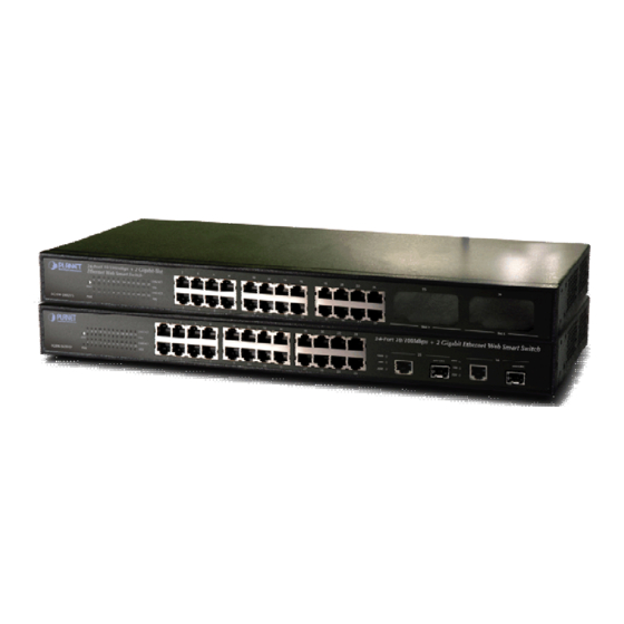
The Front Panel of the Web Smart Ethernet Switch consists of 24x Auto-Sensing 10/100Mbps Ethernet RJ-45 Ports, the FGSW-2402VS provide two open slots can be installed by optionally two of 1000Base-T port, 100Base-FX, or 1000Base- SX/LX fiber-optic interfaces. Also the FGSW-2620VSF provides 2 Gigabit TP/SFP combo ports either can be 1000Base-T for 10/100/1000Mbps or 1000Base-SX/LX through SFP (Small Factor Pluggable) interface. -
Page 8: Rear Panel
Notice: 1. Press the RESET button once. The Web Smart Switch will reboot automatically. 2. Press the RESET button for 5 seconds. The Web Smart Switch will back to the factory default mode; the entire con- figuration will be erased. - Page 9 Step 4: Follow the same steps to attach the second bracket to the opposite side. Step 5: After the brackets are attached to the Web Smart Switch, use suitable screws to securely attach the brackets to the rack, as shown in Figure 2-5.
-
Page 10: Switch Management
The Web Smart Switch must have an Internet Protocol (IP) address accessible for the remote host. 3.3 Logging on to the FGSW-2402VS/FGSW-2620VSF When you log on to the Web Smart Switch Web interface for the first time, a sign-on string appears and you are prompted for a Web login username and password. -
Page 11: Web Management
To modify your PC’s IP domain to the same with Web Smart Switch then use the default IP address (192.168.0.100) to remote configure Web Smart Switch through the Web interface. Notice: The following section will base on the console screens of FGSW-2620VSF, for FGSW-2402VS the display will be the same to FGSW-2620VSF. 4.1 Login in to the Switch To access the Web-browser interface you must first enter the user name and password, the default user name and password is "admin”. -
Page 12: Port Status
Figure 4-2 Web main menu screen 4-2 Port Status This section provides current status of each port from Web Smart Switch, the screen in Figure 4-3 appears and table 4-1 describes the port status object of Web Smart Switch. Figure 4-3 Port Status Web Page screen... -
Page 13: Port Configuration
Display the flow control On or Off state of each port on Web Smart Switch. Refresh button Press this button for refresh current status of each port on Web Smart Switch. Table 4-1 Descriptions of the Port Status screen Objects 4-3 Port Configuration This section introduces detail settings of per port on Web Smart Switch;... - Page 14 100H, 10F, 10H. Default mode is Auto. Flow Control Per port Flow control Disable (Off) or enable (On) on Web Smart Switch. Default mode is On. Input the value of packet rate sent from the connected port to this port must enable the flow control InRate feature of this port for the function to work normally.
-
Page 15: Trunk Configuration
4-4 Trunk configuration This function allows to configuring the trunk function. It provides up to 7 trunk groups and each trunk group provides 2 to 8 member ports. Please check the member port from “Normal” to 7 trunk groups and the screen in pears. - Page 16 Figure 4-8 Trunk Configuration Web Page screen Please press “Back” for return to Trunk configuration screen for further configuration. If the member port from each trunk group is out of range or less than 2 ports than the following screen appears. Figure 4-9 Trunk Configuration Web Page screen Please press “Back”...
-
Page 17: Vlan Configuration
A Virtual LAN (VLAN) is a logical network grouping that limits the broadcast domain. It allows you to isolate network traffic so only members of the VLAN receive traffic from the same VLAN members. The Web Smart Switch supports 26 port-based VLAN groups. - Page 18 Press “Relogin” to re-login the Web Smart Switch and the screen in Figure 4-12 Port-based VLAN Setting Web Page screen After login web interface of Web Smart Switch and choose VLAN configuration, the screen in Figure 4-13 Port-based VLAN Configuration Web Page screen Figure 4-12 appears.
- Page 19 Press “AddNew” button to add a port-based VLAN group and setup procedure is shown as below: Input a VLAN group ID and available range is 1-4094. Select specific port as member port and the screen in After setup completed, please press “Apply” button to take effect and the screen in Please press “Back”...
-
Page 20: Edit Existence Port-Based Vlan Group
Figure 4-16 Port-based VLAN Setting Web Page screen 4.5.2 Edit existence port-based VLAN group Click existence VLAN group ID to edit existence port-based VLAN group, the edit procedure is shown as below: - 20 -... -
Page 21: Delete Existence Port-Based Vlan Group
Select specific port as member port and the screen in After setup completed, please press “Apply” button to take effect and the screen in Please press “Back” for return to VLAN configuration screen to continue VLAN configuration. 4.5.3 Delete existence port-based VLAN group The port-based VLAN group delete procedure is shown as below: Figure 4-17 Figure 4-17 Edit Port-based VLAN Setting Web Page screen... - Page 22 Check existence VLAN group ID and the screen in Press “Delete” button to delete existence port-based VLAN group. Then the “Delete all checked groups” window appears, please press “OK” to continue the delete VLAN group procedure and the screen in Figure 4-20 Please press “Back”...
-
Page 23: Disable Port-Based Vlan Function
4.5.4 Disable port-based VLAN function Select “Disable” and pop window appears, press “OK” to disable the port-based VLAN function then the Web Smart Switch will reboot for take affect. The screen in Figure 4-21 Delete Port-based VLAN group Web Page screen Figure 4-22 Port-based VLAN group Web Page screen Figure 4-23 &... - Page 24 Figure 4-23 Disable Port-based VLAN function Web Page screen Figure 4-24 Disable Port-based VLAN function Web Page screen - 24 -...
- Page 25 Figure 4-25 Disable Port-based VLAN function Web Page screen Figure 4-26 Disable Port-based VLAN function Web Page screen - 25 -...
-
Page 26: Port Monitoring
This function provide to monitoring network traffic that forwards a copy of each incoming or outgoing packet from one port of a network Switch to another port where the packet can be studied. It enables the manager to keep close track of switch performance and alter it if necessary. - Page 27 1 monitored port in the Web Smart switch. Apply button Press this button for save current port monitoring configuration on Web Smart Switch. Table 4-3 Descriptions of the Port Monitoring screen Objects Figure 4-28 Port Monitoring Web Page screen...
-
Page 28: Qos Configuration
Highest:secHigh:SecLow:Lowest=15:10:5:1 Default mode is Highest:secHigh:SecLow:Lowest=8:4:2:1, the screen in pears. Allow to assign Ingress priority on each port of Web Smart Switch, the available options are Static Port Ingress Priority OFF and 0-7. Default mode is 0 and the screen in Allow assign high and low on each priority, the available options are shown as below: 802.1p Priority [7-0]... - Page 29 Figure 4-30 QoS Configuration Web Page screen Figure 4-31 QoS Configuration Web Page screen - 29 -...
-
Page 30: Port Counters
Figure 4-32 QoS Configuration Web Page screen 4-8 Port counters This function could provide you with an individual statistical counter; it is a useful page for administrator to monitor each port’s usage condition. Also, it is helpful to troubleshooting network problems. The screen in Figure 4-33 &... - Page 31 Figure 4-33 Port Counters Web Page screen Figure 4-34 Port Counters Web Page screen Press “ClearAllCntr” button to refresh current per port counters on Web Smart Switch. - 31 -...
-
Page 32: Access Control List
The screen in following screen appears; table 4-5 descriptions the Access Control List of Web Smart Switch. - Page 33 Figure 4-36 Access Control List (ACL) Web Page screen Figure 4-37 Access Control List (ACL) Web Page screen - 33 -...
- Page 34 Figure 4-38 Access Control List (ACL) Web Page screen Figure 4-39 Access Control List (ACL) Web Page screen - 34 -...
- Page 35 Figure 4-40 Access Control List (ACL) Web Page screen Figure 4-41 Access Control List (ACL) Web Page screen - 35 -...
- Page 36 Figure 4-42 Access Control List (ACL) Web Page screen Figure 4-43 Access Control List (ACL) Web Page screen - 36 -...
- Page 37 Figure 4-44 Access Control List (ACL) Web Page screen Figure 4-45 Access Control List (ACL) Web Page screen - 37 -...
- Page 38 Figure 4-46 Access Control List (ACL) Web Page screen Figure 4-47 Access Control List (ACL) Web Page screen - 38 -...
- Page 39 Figure 4-48 Access Control List (ACL) Web Page screen Figure 4-49 Access Control List (ACL) Web Page screen - 39 -...
-
Page 40: Web Smart Function
4-10 Web Smart Function This function could provide you to define device indicate connect to each port on Web Smart Switch, the screen in 4-50 appears. Figure 4-50 Web Smart Funciton Web Page screen The available options are shown as below:... - Page 41 Figure 4-51 Web Smart Funciton Web Page screen Figure 4-52 Web Smart Funciton Web Page screen - 41 -...
- Page 42 This function also provides Apply for all ports option from Select a port function, the setup procedure shown as below: Choose a device and check “Apply for all ports” from options of Select a port function, the screen in appears. Check any port then all port will be select;...
- Page 43 Figure 4-54 Web Smart Funciton Web Page screen Figure 4-55 Web Smart Funciton Web Page screen - 43 -...
- Page 44 Figure 4-56 Web Smart Funciton Web Page screen Figure 4-57 Web Smart Funciton Web Page screen - 44 -...
-
Page 45: Misc Operation
Collision Retry Forever. MAC Table Auto-Aging. MAC Table Hashing. Web Auto Logout Time. Please refer to section 4.11.1 for detail description. Provide firmware upgrade on Web Smart Switch; please refer to section 4.11.2 for detail de- TFTP Firmware Up- date scription. -
Page 46: Switch Configuration
Provide Collision Retry Forever function ”Disable” or ”Enable” on Web Smart Switch; If this func- Forever tion is disabled, when a packet meet a collision, the Web Smart Switch will retry 6 times before discard the packets. Otherwise, the Web Smart Switch will retry until the packet is successfully sent. - Page 47 Figure 4-60 Switch Configuration Web Page screen Figure 4-61 Switch Configuration Web Page screen - 47 -...
- Page 48 Figure 4-62 Switch Configuration Web Page screen Figure 4-63 Switch Configuration Web Page screen - 48 -...
-
Page 49: Tftp Firmware Upgrade
4.11.2 TFTP Firmware Upgrade This section provides Firmware upgrade through TFTP method on Web Smart Switch, the screen in Figure 4-64 appears. Figure 4-64 TFTP Firmware Update Web Page screen - 49 -... -
Page 50: Password Setting
User Name Name is admin. New Password Provide to modify and input a new password on Web Smart Switch; maximum up to six characters. Default password is admin. Password Again Provide to input again new password for confirm on Web Smart Switch; maximum up to six char- acters. -
Page 51: Ip Configuration
Default Gateway Provide to modify Default Gateway on Web Smart Switch. Default Gateway is 192.168.0.254. Apply button Press this button for save current IP Configuration on Web Smart Switch. Once press the Apply button then the pop window with “IP changed. Please Click OK to Re-login” appears. Press “OK”... -
Page 52: Factory Default
Please press “OK” button to take effect and the switch will reset to factory default mode and ask you to waiting rebooting around 10 sec, press “OK” button to re-login the Web Smart Switch. The screen in 4-69 & 4-70 appears. - Page 53 Figure 4-69 Factory Default Web Page screen Figure 4-70 Factory Default Web Page screen - 53 -...
-
Page 54: Reboot System
This section provides Reboot function on Web Smart Switch, after choose this function and the following screen appears in Figure 4-71. Please press “OK” button to take effect and the switch will reboot and ask you to waiting rebooting around 10 sec, press “OK” button to re-login the Web Smart Switch. The screen in Figure 4-72 &... - Page 55 Figure 4-73 Reboot Web Page screen Figure 4-74 Reboot Web Page screen - 55 -...
-
Page 56: System Information
4.11.7 System Information This section display system information on Web Smart Switch, after choose this function and the following screen appears Figure 4-75. Figure 4-75 System Information Web Page screen - 56 -... -
Page 57: Logout
4-12 Logout This section provide web logout function on Web Smart Switch, after choose this function and the following screen appears Figure 4-76. Please press “OK” button to take effect and Logout pop window appears, press “OK” button to re-login the Web Smart Switch. - Page 58 Figure 4-77 Logout Web Page screen Figure 4-78 Logout Web Page screen - 58 -...
- Page 59 Figure 4-79 Logout Web Page screen - 59 -...
-
Page 60: Switch Operation
5.2 Learning When one packet comes in from any port. The Switch will record the source address, port no. And the other related information in address table. This information will be used to decide either forwarding or filtering for future packets. -
Page 61: Troubleshooting
Performance is bad Solution: Check the full duplex status of the Ethernet Switch. If the Ethernet Switch is set to full duplex and the partner is set to half duplex, then the performance will be poor. 100Base-TX port link LED is lit, but the traffic is irregular Solution: Check that the attached device is not set to dedicate full duplex. -
Page 62: Appendix A Networking Connection
A.1 Switch‘s RJ-45 Pin Assignments 1000Mbps, 1000Base T Contact BI_DA+ BI_DA- BI_DB+ BI_DC+ BI_DC- BI_DB- BI_DD+ BI_DD- 10/100Mbps, 10/100Base-TX RJ-45 Connector pin assignment Contact Media Dependant Interface Tx + (transmit) Tx - (transmit) Rx + (receive) 4, 5 Rx - (receive) 7, 8 A.2 RJ-45 cable pin assignment... - Page 63 There are 8 wires on a standard UTP/STP cable and each wire is color-coded. The following shows the pin allocation and color of straight cable and crossover cable connection: Figure A-1: Straight-Through and Crossover Cable Please make sure your connected cables are with same pin assignment and color as above picture before deploying the cables into your network.
Need help?
Do you have a question about the FGSW-2402VS and is the answer not in the manual?
Questions and answers