ABB ACS350 User Manual
Hide thumbs
Also See for ACS350:
- User manual (52 pages) ,
- Installation instructions (2 pages) ,
- User manual (314 pages)
Table of Contents
Advertisement
Quick Links
Advertisement
Chapters
Table of Contents

Related Manuals for ABB ACS350


Summary of Contents for ABB ACS350
- Page 1 ACS350 User’s Manual ACS350 Drives (0.37…22 kW, 0.5…30 HP)
-
Page 2: Acs350 Drive Manuals
3AFE68591082 (EN, DA, DE, ES, FI, FR, IT, NL, PT, RU, SV) MTAC-01 Pulse Encoder Interface Module User’s Manual 3AFE68591091 (EN) MUL1-R1 Installation Instructions for ACS150 and ACS350 3AFE68642868 (EN, DA, DE, ES, FI, FR, IT, NL, PT, RU, SV) MUL1-R3 Installation Instructions for ACS150 and ACS350... - Page 3 ACS350 Drives 0.37…22 kW 0.5…30 HP User’s Manual 3AFE68462401 Rev D EFFECTIVE: 30.09.2007 © 2007 ABB Oy. All Rights Reserved.
-
Page 5: Safety
Safety What this chapter contains The chapter contains the safety instructions which you must follow when installing, operating and servicing the drive. If ignored, physical injury or death may follow, or damage may occur to the drive, motor or driven equipment. Read the safety instructions before you work on the drive. -
Page 6: Installation And Maintenance Work
• The drive is not field repairable. Never attempt to repair a malfunctioning drive; contact your local ABB representative or Authorized Service Center for replacement. • Make sure that dust from drilling does not enter the drive during the installation. -
Page 7: Operation And Start-Up
Operation and start-up These warnings are intended for all who plan the operation, start up or operate the drive. WARNING! Ignoring the following instructions can cause physical injury or death, or damage to the equipment. • Before adjusting the drive and putting it into service, make sure that the motor and all driven equipment are suitable for operation throughout the speed range provided by the drive. - Page 8 Safety...
-
Page 9: Table Of Contents
Providing feedback on ABB Drives manuals ........ - Page 10 AC power line connection ............29 Supply disconnecting device .
- Page 11 ABB Standard macro ........
- Page 12 Program features What this chapter contains ............95 Start-up Assistant .
- Page 13 DC Hold ..............108 Settings .
- Page 14 Diagnostics ............. . . 119 Parameter lock .
- Page 15 Parameters – complete descriptions ..........159 10 START/STOP/DIR .
- Page 16 ABB Drives communication profile ........
- Page 17 LEDs ............... 287 Technical data What this chapter contains .
-
Page 18: Table Of Contents
Table of contents... -
Page 19: About The Manual
Product and service inquiries Address any inquiries about the product to your local ABB representative, quoting the type code and serial number of the unit in question. A listing of ABB sales, support and service contacts can be found by navigating to www.abb.com/drives... -
Page 20: Installation And Commissioning Flowchart
Installation and commissioning flowchart Task Identify the frame size of your drive: R0…R4. Technical data: Ratings on page Plan the installation: select the cables, etc. Planning electrical installation on page Check the ambient conditions, ratings and required Technical data on page cooling air flow. -
Page 21: Hardware Description
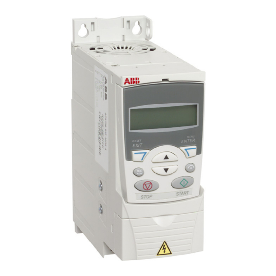
The chapter describes the construction and type code information in short. Overview The ACS350 is a wall or cabinet mountable drive for controlling AC motors. The construction of frame sizes R0…R4 varies to some extent. Covers on (R0 and R1) -
Page 22: Overview: Connections
Overview: Connections The diagram gives an overview of connections. I/O connections are parameterable. The diagram shows the default I/O connections for the ABB standard macro. See chapter Application macros for I/O connections for the different macros and chapter Electrical installation for installation in general. -
Page 23: Type Code
You find the type code on the type designation label attached to the drive. The first digits from the left express the basic configuration, for example ACS350-03E- 08A8-4. The optional selections are given after that, separated by + signs, for example +J404. - Page 24 Hardware description...
-
Page 25: Mechanical Installation
Mechanical installation What this chapter contains The chapter describes the mechanical installation procedure of the drive. Unpacking the drive The drive (1) is delivered in a package that also contains the following items (frame size R1 shown in the figure): •... -
Page 26: Delivery Check
(the label of your drive shows the valid markings) Before installation The ACS350 may be installed on the wall or in a cabinet. Check the enclosure requirements for the need to use the NEMA 1 option in wall installations (see chapter Technical data). -
Page 27: Mounting The Drive
Mounting the drive Mount the drive Note: Make sure that dust from drilling does not enter the drive during the installation. With screws 1. Mark the locations for the holes using e.g. the mounting template cut out from the package. The locations of the holes are also shown in the drawings in chapter Dimensions. -
Page 28: Fasten Clamping Plates
Fasten clamping plates See Figure a below. 1. Fasten the clamping plate to the plate at the bottom of the drive with the provided screws. 2. Fasten the I/O clamping plate to the clamping plate (frame sizes R0…R2) with the provided screws. -
Page 29: Planning Electrical Installation
Note: The installation must always be designed and made according to applicable local laws and regulations. ABB does not assume any liability whatsoever for any installation which breaches the local laws and/or other regulations. -
Page 30: Thermal Overload And Short-Circuit Protection
Circuit breakers which have been tested by ABB with the ACS350 can be used. Fuses must be used with other circuit breakers. Contact your local ABB representative for the approved breaker types and supply network characteristics. -
Page 31: Protection Against Short-Circuit In The Motor And Motor Cable
Protection against short-circuit in the motor and motor cable The drive protects the motor and motor cable in a short-circuit situation when the motor cable is dimensioned according to the nominal current of the drive. No additional protection devices are needed. Thermal overload protection of the motor According to regulations, the motor must be protected against thermal overload and the current must be switched off when overload is detected. -
Page 32: Selecting The Power Cables
Selecting the power cables General rules Dimension the input power and motor cables according to local regulations. • The cable must be able to carry the drive load current. See chapter Technical data for the rated currents. ° • The cable must be rated for at least 70 C maximum permissible temperature of the conductor in continuous use. -
Page 33: Motor Cable Shield
Motor cable shield To function as a protective conductor, the shield must have the same cross-sectional area as the phase conductors when they are made of the same metal. To effectively suppress radiated and conducted radio-frequency emissions, the shield conductivity must be at least 1/10 of the phase conductor conductivity. The requirements are easily met with a copper or aluminium shield. -
Page 34: Protecting The Relay Output Contact And Attenuating Disturbances In Case Of Inductive Loads
Residual current device (RCD) compatibility ACS350-01x drives are suitable to be used with residual current devices of Type A, ACS350-03x drives with residual current devices of Type B. For ACS350-03x drives, other measures for protection in case of direct or indirect contact, such as separation from the environment by double or reinforced insulation or isolation from the supply system by a transformer, can also be applied. -
Page 35: Relay Cable
Control panel cable In remote use, the cable connecting the control panel to the drive must not exceed 3 m (10 ft). The cable type tested and approved by ABB is used in control panel option kits. Connection of a motor temperature sensor to the drive I/O... -
Page 36: Control Cable Ducts
A diagram of the cable routing is shown below. Motor cable Drive min. 300 mm (12 in.) Power cable Input power cable Motor cable 90 ° min. 200 mm (8 in.) min. 500 mm (20 in.) Control cables Control cable ducts 24 V 230 V 24 V 230 V... -
Page 37: Electrical Installation
Electrical installation What this chapter contains The chapter describes the electrical installation procedure of the drive. WARNING! The work described in this chapter may only be carried out by a qualified electrician. Follow the instructions in chapter Safety on page 5. Ignoring the safety instructions can cause injury or death. -
Page 38: Connecting The Power Cables
Connecting the power cables Connection diagram Drive INPUT OUTPUT V1 W1 V2 W2 BRK- BRK+ For alternatives, see section Supply Optional brake disconnecting device resistor on page 29. Motor Ground the other end of the PE conductor at the distribution board. Use a separate grounding cable if the conductivity of the cable shield is insufficient (smaller than the conductivity of the phase conductor) and there is no symmetrically constructed grounding conductor in the cable (see section Selecting the... -
Page 39: Procedure
1. On IT (ungrounded) systems and corner grounded TN systems, disconnect the internal EMC filter by removing the EMC screw. For 3-phase U-type drives (with type code ACS350-03U-), the EMC screw is already removed at the factory and replaced by a plastic one. -
Page 40: Connecting The Control Cables
Connecting the control cables I/O terminals The figure below shows the I/O connectors. Tightening torque is 0.5 N·m / 4.4 lbf. in. X1A: 1: SCR 9: +24 V X1B: 17: ROCOM 3 4 5 6 7 8 17 18 19 2: AI1 10: GND 18: RONC... - Page 41 Connection example of a two-wire sensor Hand/Auto, PID Control and Torque Control macros (see pages 91, 92, 93, respectively) use analog input 2 (AI2). The macro wiring diagrams for these macros show the connection when a separately powered sensor is used. The figure below gives an example of a connection using a two-wire sensor.
-
Page 42: Procedure
Procedure 1. Remove the terminal cover by simultaneously pushing the recess and sliding the cover off the frame. 2. Analog signals: Strip the outer insulation of the analog signal cable 360 degrees and ground the bare shield under the clamp. 3. -
Page 43: Installation Checklist
Installation checklist Checklist Check the mechanical and electrical installation of the drive before start-up. Go through the checklist below together with another person. Read chapter Safety the first pages of this manual before you work on the drive. Check MECHANICAL INSTALLATION The ambient operating conditions are allowed. - Page 44 Installation checklist...
-
Page 45: Start-Up, Control With I/O And Id Run
Start-up, control with I/O and ID Run What this chapter contains The chapter instructs how to: • perform the start-up • start, stop, change the direction of rotation and adjust the speed of the motor through the I/O interface • perform an Identification Run for the drive. Using the control panel to do these tasks is explained briefly in this chapter. -
Page 46: How To Perform The Limited Start-Up
POWER-UP Apply input power and wait for a moment. Check that the red LED is not lit and the green LED is lit but not blinking. The drive is now ready for use. How to perform the limited start-up For the limited start-up, you can use the Basic Control Panel or the Assistant Control Panel. - Page 47 Select the application macro (parameter 9902). The general 9902 parameter setting procedure is given above. The default value 1 (ABB STANDARD) is suitable in most cases. Select the motor control mode (parameter 9904). 9904 1 (VECTOR:SPEED) is suitable in most cases. 2 (VECTOR:TORQ) is suitable for torque control applications.
- Page 48 Enter the motor data from the motor nameplate: Note: Set the motor data to exactly the same value as on the motor nameplate. For ABB Motors example, if the motor nominal motor M2AA 200 MLA 4 speed is 1440 rpm on the...
- Page 49 IDENTIFICATION MAGNETIZATION WITH ID RUN SELECTION 0 (OFF) Press key to switch to local control (LOC shown on the left). Press to start the drive. The motor model is now calculated by magnetizing the motor for 10 to 15 s at zero speed.
- Page 50 Set the deceleration time 1 (parameter 2203). 2203 Note: Set also deceleration time 2 (parameter 2206) if two deceleration times will be used in the application. SAVING A USER MACRO AND FINAL CHECK The start-up is now completed. However, it might be useful at 9902 this stage to set the parameters required by your application and save the settings as a user macro as instructed in section...
-
Page 51: How To Perform The Guided Start-Up
How to perform the guided start-up To be able to perform the guided start-up, you need the Assistant Control Panel. Before you start, ensure that you have the motor nameplate data on hand. SAFETY The start-up may only be carried out by a qualified electrician. The safety instructions given in chapter Safety must be followed during the start-up... - Page 52 After completing a set-up task, the Start-up Assistant suggests the CHOICE Do you want to next one. continue with application setup? • Press (when is highlighted) to continue with the Continue Continue Skip suggested task. EXIT 00:00 • Press key to highlight and then press to move to...
-
Page 53: How To Control The Drive Through The I/O Interface
Ensure that the control connections are wired according to the See section ABB Standard macro on page 87. connection diagram given for the ABB Standard macro. Ensure that the drive is in remote control. Press key to switch In remote control, the panel display shows text REM. -
Page 54: How To Perform The Id Run
How to perform the ID Run The drive estimates motor characteristics automatically when the drive is started for the first time and after any motor parameter (group 99 START-UP DATA) is changed. This is valid when parameter 9910 ID RUN has value 0 (OFF/IDMAGN). In most applications there is no need to perform a separate ID Run. - Page 55 ID RUN WITH THE BASIC CONTROL PANEL Change parameter 9910 ID RUN to 1 (ON). Save the new 9910 setting by pressing If you want to monitor actual values during the ID Run, go to the Output mode by pressing repeatedly until you get there.
- Page 56 Start-up, control with I/O and ID Run...
-
Page 57: Control Panels
About control panels Use a control panel to control the ACS350, read status data, and adjust parameters. The ACS350 works with either of two different control panel types: •... -
Page 58: Basic Control Panel
Basic Control Panel Features The Basic Control Panel features: • numeric control panel with an LCD display • copy function – parameters can be copied to the control panel memory for later transfer to other drives or for backup of a particular system. Overview The following table summarizes the key functions and displays on the Basic Control Panel. -
Page 59: Operation
Operation You operate the control panel with the help of menus and keys. You select an option, e.g. operation mode or parameter, by scrolling the arrow keys until the option is visible in the display and then pressing the key. With the key, you return to the previous operation level without saving the made changes. - Page 60 How to start, stop and switch between local and remote control You can start, stop and switch between local and remote control in any mode. To be able to start or stop the drive, the drive must be in local control. Step Action Display...
-
Page 61: Output Mode
Output mode In the Output mode, you can: • monitor actual values of up to three group 01 OPERATING DATA signals, one signal at a time • start, stop, change the direction and switch between local and remote control. You get to the Output mode by pressing until the display shows text OUTPUT at the bottom. -
Page 62: Reference Mode
Reference mode In the Reference mode, you can: • set the speed, frequency or torque reference • start, stop, change the direction and switch between local and remote control. How to set the speed, frequency or torque reference Step Action Display Go to the Main menu by pressing if you are in the Output mode,... -
Page 63: Parameter Mode
Parameter mode In the Parameter mode, you can: • view and change parameter values • select and modify the signals shown in the Output mode • start, stop, change the direction and switch between local and remote control. How to select a parameter and change its value Step Action Display... - Page 64 How to select the monitored signals Step Action Display You can select which signals are monitored in the Output mode and how they are displayed with group 34 PANEL DISPLAY parameters. See page for detailed instructions on changing parameter values. By default, the display shows three signals.
-
Page 65: Copy Mode
Copy mode The Basic Control Panel can store a full set of drive parameters and up to three user sets of drive parameters to the control panel. The control panel memory is non- volatile. In the Copy mode, you can do the following: •... -
Page 66: Basic Control Panel Alarm Codes
How to upload and download parameters For the upload and download functions available, see above. Step Action Display Go to the Main menu by pressing if you are in the Output mode, otherwise by pressing repeatedly until you see MENU at the bottom. MENU CoPY If the panel is not in the Copy mode (“CoPY”... -
Page 67: Assistant Control Panel
Assistant Control Panel Features The Assistant Control Panel features: • alphanumeric control panel with an LCD display • language selection for the display • Start-up Assistant to ease drive commissioning • copy function – parameters can be copied to the control panel memory for later transfer to other drives or for backup of a particular system. -
Page 68: Operation
Status line The top line of the LCD display shows the basic status information of the drive. MAIN MENU 49.1Hz No. Field Alternatives Significance Control location Drive control is local, that is, from the control panel. Drive control is remote, such as the drive I/O or fieldbus. - Page 69 Initially, the panel is in the Output mode, where you can 49.1Hz start, stop, change the direction, switch between local and 1 Hz remote control, modify the reference value and monitor up to three actual values. To do other tasks, go first to the Main menu and select the appropriate mode on the menu.
- Page 70 How to get help Step Action Display Press to read the context-sensitive help text for the item that is highlighted. PAR GROUPS 01 OPERATING DATA 03 FB ACTUAL SIGNALS 04 FAULT HISTORY 10 START/STOP/DIR 11 REFERENCE SELECT EXIT 00:00 HELP If help text exists for the item, it is shown on the display.
- Page 71 How to start, stop and switch between local and remote control You can start, stop and switch between local and remote control in any mode. To be able to start or stop the drive, the drive must be in local control. Step Action Display...
-
Page 72: Output Mode
Output mode In the Output mode, you can: • monitor actual values of up to three signals in group 01 OPERATING DATA • change the direction of the motor rotation • set the speed, frequency or torque reference • adjust the display contrast •... - Page 73 How to set the speed, frequency or torque reference Step Action Display EXIT If you are not in the Output mode, press repeatedly until you get there. 49.1Hz 1 Hz 00:00 MENU If the drive is in remote control (REM shown on the status line), switch to local 49.1Hz 1 Hz control by pressing...
-
Page 74: Parameters Mode
Select the appropriate parameter with keys . The current PARAMETERS 9901 LANGUAGE value of the parameter is shown below the selected parameter. 9902 APPLIC MACRO ABB STANDARD 9904 MOTOR CTRL MODE 9905 MOTOR NOM VOLT EXIT 00:00 EDIT PAR EDIT... - Page 75 How to select the monitored signals Step Action Display You can select which signals are monitored in the Output mode and how they PAR EDIT are displayed with group 34 PANEL DISPLAY parameters. See page 3401 SIGNAL1 PARAM OUTPUT FREQ detailed instructions on changing parameter values.
-
Page 76: Assistants Mode
Assistants mode When the drive is first powered up, the Start-up Assistant guides you through the setup of the basic parameters. The Start-up Assistant is divided into assistants, each of which is responsible for the specification of a related parameter set, for example Motor Set-up or PID Control. -
Page 77: Changed Parameters Mode
Step Action Display • To accept the new value and continue to the setting of the next parameter, PAR EDIT SAVE press 9906 MOTOR NOM CURR 1.2 A EXIT • To stop the assistant, press EXIT 00:00 SAVE Changed Parameters mode In the Changed Parameters mode, you can: •... -
Page 78: Fault Logger Mode
Fault Logger mode In the Fault Logger mode, you can: • view the drive fault history of maximum ten faults (after a power off, only the three latest faults are kept in the memory) • see the details of the three latest faults (after a power off, the details of only the most recent fault is kept in the memory) •... -
Page 79: Time And Date Mode
Time and Date mode In the Time and Date mode, you can: • show or hide the clock • change date and time display formats • set the date and time • enable or disable automatic clock transitions according to the daylight saving changes •... - Page 80 Step Action Display SET DATE • To set the date, select SET DATE on the menu and press . Specify the first part of the date (day or month depending on the selected date format) with 19.03.05 keys , and press .
-
Page 81: Parameter Backup Mode
Parameter Backup mode The Parameter Backup mode is used to export parameters from one drive to another or to make a backup of the drive parameters. Uploading to the panel stores all drive parameters, including up to three user sets, to the Assistant Control Panel. The full set, partial parameter set (application) and user sets can then be downloaded from the control panel to another drive or the same drive. - Page 82 How to upload and download parameters For the upload and download functions available, see above. Step Action Display MENU Go to the Main menu by pressing if you are in the Output mode, otherwise MAIN MENU PARAMETERS EXIT by pressing repeatedly until you get to the Main menu.
- Page 83 Select BACKUP INFO on the Par Backup with keys , and BACKUP INFO DRIVE TYPE press . The display shows the following information about the drive where ACS350 the backup was made: 3304 DRIVE RATING 2A41i DRIVE TYPE: type of the drive...
-
Page 84: I/O Settings Mode
I/O Settings mode In the I/O Settings mode, you can: • check the parameter settings related to any I/O terminal • edit the parameter setting. For example, if “1103: REF1” is listed under Ain1 (Analog input 1), that is, parameter 1103 REF1 SELECT has value AI1, you can change its value to e.g. -
Page 85: Application Macros
9902 APPLIC MACRO, makes the essential changes and saves the result as a user macro. The ACS350 has seven standard macros and three user macros. The table below contains a summary of the macros and describes suitable applications. Macro Suitable applications... -
Page 86: Summary Of I/O Connections Of Application Macros
Summary of I/O connections of application macros The following table gives the summary of the default I/O connections of all application macros. Macro Input/output Motor Torque 3-wire Alternate Hand/Auto PID Control Standard Potentiom. Control Freq. ref. Speed ref. Speed ref. Speed ref. -
Page 87: Abb Standard Macro
ABB Standard macro This is the default macro. It provides a general purpose I/O configuration with three constant speeds. Parameter values are the default values given in chapter Actual signals and parameters, starting from page 142. If you use other than the default connections presented below, see section terminals on page 40. -
Page 88: 3-Wire Macro
3-wire macro This macro is used when the drive is controlled using momentary push-buttons. It provides three constant speeds. To enable the macro, set the value of parameter 9902 to 2 (3-WIRE). For the parameter default values, see section Default values with different macros on page 142. -
Page 89: Alternate Macro
Alternate macro This macro provides an I/O configuration adapted to a sequence of DI control signals used when alternating the rotation direction of the drive. To enable the macro, set the value of parameter 9902 to 3 (ALTERNATE). For the parameter default values, see section Default values with different macros on page 142. -
Page 90: Motor Potentiometer Macro
Motor Potentiometer macro This macro provides a cost-effective interface for PLCs that vary the speed of the drive using only digital signals. To enable the macro, set the value of parameter 9902 to 4 (MOTOR POT). For the parameter default values, see section Default values with different macros on page 142. -
Page 91: Hand/Auto Macro
Hand/Auto macro This macro can be used when switching between two external control devices is needed. To enable the macro, set the value of parameter 9902 to 5 (HAND/AUTO). For the parameter default values, see section Default values with different macros on page 142. -
Page 92: Pid Control Macro
PID Control macro This macro provides parameter settings for closed-loop control systems such as pressure control, flow control, etc. Control can also be switched to speed control using a digital input. To enable the macro, set the value of parameter 9902 to 6 (PID CONTROL). -
Page 93: Torque Control Macro
Torque Control macro This macro provides parameter settings for applications that require torque control of the motor. Control can also be switched to speed control using a digital input. To enable the macro, set the value of parameter 9902 to 8 (TORQUE CTRL). For the parameter default values, see section Default values with different macros on page 142. -
Page 94: User Macros
User macros In addition to the standard application macros, it is possible to create three user macros. The user macro allows the user to save the parameter settings, including group 99 START-UP DATA, and the results of the motor identification into the permanent memory and recall the data at a later time. -
Page 95: Program Features
Application Default tasks selection ABB STANDARD Language Select, Motor Set-up, Application, Option Modules, Speed Control EXT1, Speed Control EXT2, Start/Stop Control, Timed Functions, Protections, Output Signals 3-WIRE Language Select, Motor Set-up, Application, Option Modules, Speed Control EXT1, Speed Control... -
Page 96: List Of The Tasks And The Relevant Drive Parameters
List of the tasks and the relevant drive parameters Depending on the selection made in the Application task (parameter 9902 APPLIC MACRO), the Start-up Assistant decides which consequent tasks it suggests. Name Description Set parameters Language Select Selecting the language 9901 Motor Set-up Setting the motor data... -
Page 97: Contents Of The Assistant Displays
Embedded fieldbus or an optional fieldbus adapter enables control over an open fieldbus link. A PC equipped with DriveWindow Light PC tool can also control the drive. Local Control ACS350 External Control Control panel Panel connection (X2) -
Page 98: Local Control
Local control The control commands are given from the control panel keypad when the drive is in local control. LOC indicates local control on the panel display. Assistant panel Basic panel 49.1Hz 1 Hz OUTPUT 00:00 MENU The control panel always overrides the external control signal sources when used in local mode. -
Page 99: Block Diagram: Start, Stop, Direction Source For Ext1
Block diagram: Start, stop, direction source for EXT1 The figure below shows the parameters that select the interface for start, stop, and direction for external control location EXT1. Select EXT1 Start/stop/ Fb. selection direction See chapters Fieldbus COMM control with embedded Embedded fieldbus 1001 fieldbus... -
Page 100: Reference Types And Processing
Reference types and processing The drive can accept a variety of references in addition to the conventional analog input and control panel signals. • The drive reference can be given with two digital inputs: One digital input increases the speed, the other decreases it. •... -
Page 101: Reference Trimming
Reference trimming In reference trimming, the external reference is corrected depending on the measured value of a secondary application variable. The block diagram below illustrates the function. 1105 REF1 MAX / 1108 REF 2 MAX Switch Select Switch DIRECT (2) max.freq REF1 (Hz/rpm) / PROPOR. -
Page 102: Example
Example The drive runs a conveyor line. It is speed controlled but the line tension also needs to be taken into account: If the measured tension exceeds the tension setpoint, the speed will be slightly decreased, and vice versa. To accomplish the desired speed correction, the user •... -
Page 103: Diagnostics
Diagnostics Actual value Additional information 0120, 0121 Analog input values 1401 AI1/A2 signal loss Alarm AI1 LOSS AI2 LOSS AI1/AI2 signal below AI1/AI2 FAULT LIMIT (3021/3022) Fault AI1 LOSS AI2 LOSS AI1/AI2 signal below limit AI1/AI2 FAULT LIMIT (3021/3022) PAR AI SCALE Incorrect AI signal scaling (1302 <... -
Page 104: Settings
Settings Parameter Additional information Group 10 START/STOP/DIR DI as start, stop, direction Group 11 REFERENCE SELECT DI in reference selection, or reference source Group 12 CONSTANT SPEEDS DI in constant speed selection Group 16 SYSTEM CONTROLS DI as external Run Enable, fault reset or user macro change signal Group 19 TIMER &... -
Page 105: Frequency Input
Frequency input Digital input DI5 can be programmed as a frequency input. Frequency input (0...16000 Hz) can be used as external reference signal source. The update time for the frequency input is 50 ms. Update time is shorter when information is transferred to the application program (50 ms ->... -
Page 106: Actual Signals
Actual signals Several actual signals are available: • Drive output frequency, current, voltage and power • Motor speed and torque • Intermediate circuit DC voltage • Active control location (LOCAL, EXT1 or EXT2) • Reference values • Drive temperature • Operating time counter (h), kWh counter •... -
Page 107: Power Loss Ride-Through
Power loss ride-through If the incoming supply voltage is cut off, the drive will continue to operate by utilising the kinetic energy of the rotating motor. The drive will be fully operational as long as the motor rotates and generates energy to the drive. The drive can continue the operation after the break if the main contactor remained closed. -
Page 108: Dc Hold
DC Hold Motor By activating the motor DC Hold feature it is possible to speed lock the rotor at zero speed. When both the reference DC Hold and the motor speed fall below the preset DC hold speed, the drive stops the motor and starts to inject DC DC hold speed into the motor. -
Page 109: Settings
Braking Torque (%) Flux Braking Rated Motor Power 7.5 kW 2.2 kW 0.37 kW f / (Hz) Braking Torque (%) No Flux Braking Rated Motor Power 7.5 kW 2.2 kW 0.37 kW f / (Hz) The drive monitors the motor status continuously, also during the Flux Braking. Therefore, Flux Braking can be used both for stopping the motor and for changing the speed. -
Page 110: Flux Optimisation
Flux Optimisation Flux Optimisation reduces the total energy consumption and motor noise level when the drive operates below the nominal load. The total efficiency (motor and the drive) can be improved by 1% to 10%, depending on the load torque and speed. Settings Parameter 2601... -
Page 111: Constant Speeds
Constant speeds It is possible to define seven positive constant speeds. Constant speeds are selected with digital inputs. Constant speed activation overrides the external speed reference. Constant speed selections are ignored if • torque control is active, or • PID reference is being followed, or •... -
Page 112: Custom U/F Ratio
Custom U/f ratio The user can define a U/f curve (output voltage as a function of frequency). This custom ratio is used only in special applications where linear and squared U/f ratio are not sufficient (e.g. when motor break-away torque needs to be boosted). Custom U/f ratio Voltage (V) par. -
Page 113: Speed Controller Tuning
Speed controller tuning It is possible to manually adjust the controller gain, integration time and derivation time, or let the drive perform a separate speed controller Autotune Run (parameter 2305 AUTOTUNE RUN). In Autotune Run, the speed controller is tuned based on the load and inertia of the motor and the machine. -
Page 114: Speed Control Performance Figures
Speed control performance figures The table below shows typical performance figures for speed control. load Speed control No pulse With pulse encoder encoder Static accuracy 20% of motor 2% of motor nominal slip nominal slip Dynamic < 1% s with 100% <... -
Page 115: Scalar Control
Scalar control It is possible to select scalar control as the motor control method instead of vector control. In the scalar control mode, the drive is controlled with a frequency reference. It is recommended to activate the scalar control mode in the following special applications: •... -
Page 116: External Fault 2
External Fault External Faults (1 and 2) can be supervised by defining one digital input as a source for an external fault indication signal. Settings Parameters 3003 EXTERNAL FAULT 1 and 3004 EXTERNAL FAULT 2 Stall Protection The drive protects the motor in a stall situation. It is possible to adjust the supervision limits (frequency, time) and choose how the drive reacts to the motor stall condition (alarm indication / fault indication &... -
Page 117: Underload Protection
Underload Protection Loss of motor load may indicate a process malfunction. The drive provides an underload function to protect the machinery and process in such a serious fault condition. Supervision limits - underload curve and underload time - can be chosen as well as the action taken by the drive upon the underload condition (alarm indication / fault indication &... -
Page 118: Drive Temperature
Drive temperature The drive supervises the IGBT temperature. There are two supervision limits: Alarm limit and fault trip limit. Short circuit If a short circuit occurs, the drive will not start and a fault indication is given. Internal fault If the drive detects an internal fault, the drive is stopped and a fault indication is given. -
Page 119: Supervisions
Supervisions The drive monitors whether certain user selectable variables are within the user-defined limits. The user may set limits for speed, current etc. The supervision status can be indicated through relay or digital output. The supervision functions operate on a 2 ms time level. Settings Parameter group 32 SUPERVISION... -
Page 120: Pid Control
Example: PID control block diagram Pressure boost pump %ref A C S 6 0 0 ACS350 4001 4002 Switch Frequency A C T P A R . - Page 121 The following figure presents the speed/scalar control block diagram for process controller PID1. Program features...
-
Page 122: Settings
Settings Parameter Additional information 1101 Local control mode reference type selection 1102 EXT1/2 selection 1106 PID1 activation 1107 REF2 minimum limit 1501 PID2 output (external controller) connection to AO 9902 PID control macro selection Group 40 PROCESS PID SET PID1 settings 1...41 PROCESS PID SET 2 Group 42 EXT / TRIM PID... -
Page 123: Example
Example The time scheme below visualises the operation of the sleep function. Motor speed = Sleep delay, parameter 4024 = Wake-up delay, parameter 4026 t<t Sleep level par. 4023 Text on display SLEEP MODE STOP START Actual value Wake-up deviation par. -
Page 124: Motor Temperature Measurement Through The Standard I/O
Motor temperature measurement through the standard I/O This section describes the temperature measurement of one motor when the drive I/ O terminals are used as the connection interface. Motor temperature can be measured using PT100 or PTC sensors connected to analog input and output. -
Page 125: Settings
It is also possible to monitor motor temperature by connecting a PTC sensor and a thermistor relay between the +24 VDC voltage supply offered by the drive and digital input. The figure below displays the connection. Par. 3501 = THERM(0) or THERM(1) Thermistor relay DI1...5... -
Page 126: Control Of A Mechanical Brake
Control of a mechanical brake The mechanical brake is used for holding the motor and driven machinery at zero speed when the drive is stopped, or not powered. Example The figure below shows a brake control application example. WARNING! Make sure that the machinery into which the drive with brake control function is integrated fulfills the personnel safety regulations. -
Page 127: Operation Time Scheme
Operation time scheme The time scheme below illustrates the operation of the brake control function. See also section State shifts on page 128. Start command External speed reference Inverter modulating Motor magnetised Open brake command (RO/DO) Internal speed reference (actual motor speed) / Torque output... -
Page 128: State Shifts
State shifts From any state (rising edge) MODULATION 0/0/1 OPEN 1/1/0 BRAKE RELEASE RFG 1/1/0 INPUT RFG = Ramp Function Generator in the speed control loop (reference RFG INPUT 1/1/1 TO ZERO handling). CLOSE 0/1/1 BRAKE State (Symbol X/Y/Z - NN: State name - X/Y/Z: State outputs/operations X = 1 Open the brake. -
Page 129: Jogging
Jogging The jogging function is typically used to control a cyclical movement of a machine section. One push button controls the drive through the whole cycle: When it is on, the drive starts, accelerates to a preset speed at a preset rate. When it is off, the drive decelerates to zero speed at a preset rate. -
Page 130: Settings
Jogging function uses constant speed 7 as jogging speed and acceleration/ deceleration ramp pair 2. It is also possible to activate jogging function 1 or 2 through fieldbus. Jogging function 1 uses constant speed 7 and jogging function 2 uses constant speed 6. Both functions use acceleration/deceleration ramp pair 2. -
Page 131: Timed Functions
Timed functions A variety of drive functions can be time controlled, e.g. start/stop and EXT1/EXT2 control. The drive offers • four start and stop times (START TIME 1...4, STOP TIME 1...4) • four start and stop days (START DAY 1...4, STOP DAY 1...4) •... -
Page 132: Settings
Example Air conditioning is active on weekdays from 8:00 to 15:30 (8 a.m to 3:30 p.m) and on Sundays from 12:00 to 15:00 (12 to 3 p.m). By pressing the extension time switch, the air-conditioning is on for an extra hour. Parameter Setting 3602... -
Page 133: Counter
Sequence programming can be applied in simple mixer applications as well as in more complicated traverse applications. The programming can be done with control panel or with a PC tool. ACS350 is supported by version 2.50 (or later version) of the DriveWindow Light PC tool which includes a graphical Sequence Programming Tool. -
Page 134: Settings
Note: As default all sequence programming parameters can be changed even when the sequence programming is active. It is recommended, that after the sequence programming parameters are set, parameters are locked by parameter 1602 PARAMETER LOCK. Settings Parameter Additional information 1001/1002 Start, stop and direction commands for EXT1/EXT2 1102... - Page 135 The state diagram below presents the state shift in sequence programming. Sequence programming 0167 bit 0 = 1 ENABLE STATE 1 0168 = 1 (State 1) (par. 8420...8424) Go to state 2 (par. 8425)* Go to state N (par 8426, 8427)* STATE 2 0168 = 2 (State 2) State N...
-
Page 136: Example 1
Example 1 50 Hz 0 Hz -50 Hz Seq. start State change trigger Sequence programming is activated by digital input DI1. ST1: Drive is started in reverse direction with -50 Hz reference and 10 s ramp time. State 1 is active for 40 s. ST2: Drive is accelerated to 20 Hz with 60 s ramp time. -
Page 137: Example 2
Example 2: Drive is programmed for traverse control with 30 sequences. Sequence programming is activated by digital input DI1. ST2 (error: acceleration too slow) AI1 + 15% AI1 + 10% AI1 - 10% ERROR AI1 - 15% Seq. start Error ST1: Drive is started in forward direction with AI1 (AI1 + 50% - 50%) reference and ramp pair 2. - Page 138 ST8 (error state): Drive is stopped with ramp pair 1. Relay output RO is activated. If sequence programming is deactivated by falling edge of digital input DI1, state machine is reset to state 1. New start command can be activated by digital input DI1 or by digital inputs DI4 and DI5 (both inputs DI4 and DI5 must be simultaneously active).
- Page 139 Additional information Par. Setting Par. Setting Par. Setting Par. Setting 8420 ST1 REF 8430 8440 8450 35% State reference 8421 START FRW 8431 START 8441 START 8451 START Start, stop and COMMANDS direction commands 8422 -0.2 (ramp 8432 1.5 s 8442 8452 1.5 s Acceleration/...
- Page 140 Program features...
-
Page 141: Actual Signals And Parameters
Actual signals and parameters What this chapter contains The chapter describes the actual signals and parameters and gives the fieldbus equivalent values for each signal/parameter. Terms and abbreviations Term Definition Actual signal Signal measured or calculated by the drive. Can be monitored by the user. No user setting possible. -
Page 142: Default Values With Different Macros
Default values with different macros When application macro is changed (9902 APPLIC MACRO), the software updates the parameter values to their default values. The following table includes the parameter default values for different macros. For other parameters, the default values are the same for all macros. See the following parameter list. Index Name/Selection 3-WIRE ALTERNATE MOTOR... -
Page 143: Actual Signals
Actual signals Actual signals Name/Value Description FbEq 01 OPERATING DATA Basic signals for monitoring the drive (read-only) 0101 SPEED & DIR Calculated motor speed in rpm. A negative value indicates reverse 1 = 1 rpm direction. 0102 SPEED Calculated motor speed in rpm 1 = 1 rpm 0103 OUTPUT FREQ... - Page 144 Actual signals Name/Value Description FbEq 0133 PID 2 DEVIATION Deviation of the PID2 controller, i.e. the difference between the reference value and the actual value. Unit depends on parameter 4106 UNIT and 4107 UNIT SCALE settings. 0134 COMM RO WORD Relay output Control Word through fieldbus (decimal).
-
Page 145: 03 Fb Actual Signals
Actual signals Name/Value Description FbEq 0169 SEQ PROG TIMER Current state time counter of the sequence programming 0170 SEQ PROG AO VAL Analog output control values defined by sequence programming. See 1 = 0.1% parameter 8423 ST1 OUT CONTROL. 0171 SEQ CYCLE CNTR Executed sequence counter of the sequence programming. - Page 146 Actual signals Name/Value Description FbEq Bit 9 = DRIVE ID Bit 10 = CONFIG FILE Bit 11 = SERIAL 1 ERR Bit 12 = EFB CON FILE. Configuration file reading error. Bit 13 = FORCE TRIP Bit 14 = MOTOR PHASE Bit 15 = OUTP WIRING 0307 FAULT WORD 3...
-
Page 147: 04 Fault History
Actual signals Name/Value Description FbEq Bit 3 = Reserved Bit 4 = START ENABLE 1 MISSING Bit 5 = START ENABLE 2 MISSING Bit 6 = EMERGENCY STOP Bit 7 = ENCODER ERROR Bit 8 = FIRST START Bit 9 = INPUT PHASE LOSS Bit 10...15 = Reserved 04 FAULT HISTORY Fault history (read-only) -
Page 148: Parameters - Short Form List
Parameters – short form list Parameters – short form list Index Name/Selection Description Custom START/STOP/DIR The sources for external start, stop and direction control 1001 EXT1 COMMANDS Defines the connections and the source for the start, stop and DI1,2 direction commands for external control location 1 (EXT1). 1002 EXT2 COMMANDS Defines the connections and the source for the start, stop and... - Page 149 Parameters – short form list Index Name/Selection Description Custom 1502 AO1 CONTENT MIN Defines the minimum value for signal selected with parameter 1501 AO1 CONTENT SEL. 1503 AO1 CONTENT MAX Defines the maximum value for signal selected with parameter 1501 AO1 CONTENT SEL. 1504 MINIMUM AO1 Defines the minimum value for the analog output signal AO.
- Page 150 Parameters – short form list Index Name/Selection Description Custom LIMITS Drive operation limits. 2001 MINIMUM SPEED Defines the allowed minimum speed. 2002 MAXIMUM SPEED Defines the allowed maximum speed. Eur: 1500 / US: 1800 2003 MAX CURRENT Defines the allowed maximum motor current. 1.8 ²...
- Page 151 Parameters – short form list Index Name/Selection Description Custom TORQUE CONTROL Torque control variables 2401 TORQ RAMP UP Defines the torque reference ramp up time. 2402 TORQ RAMP DOWN Defines the torque reference ramp down time. CRITICAL SPEEDS Speed bands within which the drive is not allowed to operate. 2501 CRIT SPEED SEL Activates/deactivates the critical speeds function.
- Page 152 Parameters – short form list Index Name/Selection Description Custom 3002 PANEL COMM ERR Selects how the drive reacts to a control panel communication FAULT break. 3003 EXTERNAL FAULT 1 Selects an interface for an external fault 1 signal. NOT SEL 3004 EXTERNAL FAULT 2 Selects an interface for an external fault 2 signal.
- Page 153 Parameters – short form list Index Name/Selection Description Custom 3206 SUPERV 2 LIM HI Defines the high limit for the second supervised signal selected by parameter 3204 SUPERV 2 PARAM. 3207 SUPERV 3 PARAM Selects the third supervised signal. 3208 SUPERV 3 LIM LO Defines the low limit for the third supervised signal selected by parameter 3207 SUPERV 3 PARAM.
- Page 154 Parameters – short form list Index Name/Selection Description Custom 3421 OUTPUT3 MAX Sets the maximum display value for the signal selected by parameter 3415 SIGNAL3 PARAM. MOTOR TEMP MEAS Motor temperature measurement. 3501 SENSOR TYPE Activates the motor temperature measurement function and NONE selects the sensor type.
- Page 155 Parameters – short form list Index Name/Selection Description Custom 4011 INTERNAL SETPNT Selects a constant value as process PID controller reference, when parameter 4010 SET POINT SEL value is set to INTERNAL. 4012 SETPOINT MIN Defines the minimum value for the selected PID reference signal source.
- Page 156 Parameters – short form list Index Name/Selection Description Custom EXT / TRIM PID External/Trim PID (PID2) control. 4201 GAIN See parameter 4001 GAIN. 4202 INTEGRATION TIME See parameter 4002 INTEGRATION TIME. 4203 DERIVATION TIME See parameter 4003 DERIVATION TIME. 4204 PID DERIV FILTER See parameter 4004 PID DERIV FILTER.
- Page 157 5318 EFB PAR 18 Reserved 5319 EFB PAR 19 ABB Drives profile (ABB DRV LIM or ABB DRV FULL) Control 0x0000 Word. Read only copy of the Fieldbus Control Word. 5320 EFB PAR 20 ABB Drives profile (ABB DRV LIM or ABB DRV FULL) Status 0x0000 Word.
- Page 158 Language selection. Definition of motor set-up data. 9901 LANGUAGE Selects the display language. ENGLISH 9902 APPLIC MACRO Selects the application macro. ABB STANDARD 9904 MOTOR CTRL MODE Selects the motor control mode. SCALAR:FREQ 9905 MOTOR NOM VOLT Defines the nominal motor voltage.
-
Page 159: Parameters - Complete Descriptions
Parameters – complete descriptions Parameters – complete descriptions Index Name/Selection Description Def, FbEq 10 START/STOP/DIR The sources for external start, stop and direction control 1001 EXT1 COMMANDS Defines the connections and the source for the start, stop and direction DI1,2 commands for external control location 1 (EXT1). - Page 160 Parameters – complete descriptions Index Name/Selection Description Def, FbEq DI5,4 Start and stop through digital input DI5. 0 = stop, 1 = start. Direction through digital input DI4. 0 = forward, 1 = reverse. To control direction, parameter 1003 DIRECTION must be REQUEST. TIMER STOP Stop when timer delay defined by parameter 1901...
-
Page 161: Reference Select
COMM Fieldbus interface as the source for EXT1/EXT2 selection, i.e. control word 0301 FB CMD WORD 1 bit 5 (with ABB Drives profile 5319 EFB PAR 19 bit 11). The control word is sent by the fieldbus controller via the fieldbus adapter or embedded fieldbus (modbus) to the drive. - Page 162 Parameters – complete descriptions Index Name/Selection Description Def, FbEq AI1/JOYST Analog input AI1 as joystick. The minimum input signal runs the motor at the maximum reference in the reverse direction, the maximum input at the maximum reference in the forward direction. Minimum and maximum references are defined by parameters 1104 REF1 MIN and...
- Page 163 Parameters – complete descriptions Index Name/Selection Description Def, FbEq AI1*AI2 Reference is calculated with the following equation: REF = AI(%) · (AI2(%) / 50%) AI1-AI2 Reference is calculated with the following equation: REF = AI1(%) + 50% - AI2(%) AI1/AI2 Reference is calculated with the following equation: REF = AI1(%) ·...
-
Page 164: Constant Speeds
Parameters – complete descriptions Index Name/Selection Description Def, FbEq COMM See parameter 1103 REF1 SELECT. COMM+AI1 See parameter 1103 REF1 SELECT. COMM*AI1 See parameter 1103 REF1 SELECT. DI3U,4D(RNC) See parameter 1103 REF1 SELECT. DI3U,4D(NC) See parameter 1103 REF1 SELECT. AI1+AI2 See parameter 1103 REF1 SELECT. - Page 165 Parameters – complete descriptions Index Name/Selection Description Def, FbEq DI1,2 Constant speed selection through digital inputs DI1 and DI2.1 = DI active, 0 = DI inactive. DI2 Operation No constant speed Speed defined by parameter 1202 CONST SPEED 1 Speed defined by parameter 1203 CONST SPEED 2 Speed defined by parameter...
- Page 166 Parameters – complete descriptions Index Name/Selection Description Def, FbEq DI2,3(INV) See selection DI1,2(INV). DI3,4(INV) See selection DI1,2(INV). DI4,5(INV) See selection DI1,2(INV). DI1,2,3(INV) Constant speed selection through inverted digital inputs DI1, DI2 and DI3. 1 = DI active, 0 = DI inactive. DI1 DI2 DI3 Operation 1 No constant speed 1 Speed defined by parameter...
-
Page 167: Analogue Inputs
Parameters – complete descriptions Index Name/Selection Description Def, FbEq 1209 TIMED MODE SEL Selects timed function activated speed into use when parameter 1201 CS1/2/3/4 CONST SPEED SEL selection is TIMED FUN1&2. EXT/CS1/2/3 External speed reference or constant speed selection with TIMED FUNC 1 and TIMED FUNC 2. -
Page 168: Relay Outputs
Parameters – complete descriptions Index Name/Selection Description Def, FbEq 1303 FILTER AI1 Defines the filter time constant for analog input AI1, i.e the time within 63% of a step change is reached. Unfiltered signal Filtered signal Time constant 0.0…10.0 s Filter time constant 1 = 0.1 s 1304... - Page 169 Parameters – complete descriptions Index Name/Selection Description Def, FbEq FAULT(RST) Fault. Automatic reset after the autoreset delay. See parameter group AUTOMATIC RESET. FLT/ALARM Fault or alarm EXT CTRL Drive is under external control. REF 2 SEL External reference REF 2 is in use. CONST FREQ A constant speed is in use.
-
Page 170: Analogue Outputs
Parameters – complete descriptions Index Name/Selection Description Def, FbEq M.TRIG RUN Run time counter is triggered. See parameter group 29 MAINTENANCE TRIG. M.TRIG MWH MWh counter is triggered. See parameter group 29 MAINTENANCE TRIG. SEQ PROG Relay output control with sequence programming. See parameter 8423 OUT CONTROL. -
Page 171: System Controls
Fieldbus interface as the source for inverted Run Enable signal (Run Disable), i.e. control word 0301 FB CMD WORD 1 bit 6 (with ABB drives profile 5319 EFB PAR 19 bit 3). The control word is sent by the fieldbus controller via the fieldbus adapter or embedded fieldbus (modbus) to the drive. - Page 172 COMM Fieldbus interface as the source for the fault reset signal, i.e. control word 0301 FB CMD WORD 1 bit 4 (with ABB drives profile 5319 EFB PAR 19 bit 7). The control word is sent by the fieldbus controller via the fieldbus adapter or embedded fieldbus (modbus) to the drive.
- Page 173 Parameters – complete descriptions Index Name/Selection Description Def, FbEq DI3,4 See selection DI1,2. DI4,5 See selection DI1,2. DI1(INV) User Parameter Set control through inverted digital input DI1. Falling edge of inverted digital input DI1: User Parameter Set 2 is loaded into use. Rising edge of inverted digital input DI1: User Parameter Set 1 is loaded into use.
- Page 174 Parameters – complete descriptions Index Name/Selection Description Def, FbEq 1607 PARAM SAVE Saves the valid parameter values to the permanent memory. DONE Note: A new parameter value of a standard macro is saved automatically when changed from the panel but not when altered through a fieldbus connection.
-
Page 175: Freq In & Tran Out
Parameters – complete descriptions Index Name/Selection Description Def, FbEq COMM Fieldbus interface as the source for the inverted Start Enable (Start Disable) signal, i.e. control word 0302 FB CMD WORD 2 bit 18 (bit 19 for Start Enable 2). The control word is sent by the fieldbus controller via the fieldbus adapter or embedded fieldbus (modbus) to the drive. -
Page 176: 19 Timer & Counter
Parameters – complete descriptions Index Name/Selection Description Def, FbEq FREQUENCY Transistor output is used as a frequency output FO. 1805 DO SIGNAL Selects a drive status indicated through digital output DO. FAULT(-1) See parameter 1401 RELAY OUTPUT 1. 1806 DO ON DELAY Defines the operation delay for digital output DO. - Page 177 Parameters – complete descriptions Index Name/Selection Description Def, FbEq DI5(INV) See selection DI1(INV). NOT SEL No start signal Timer start through digital input DI1. Timer start by rising edge of digital input DI1. Note: Timer start is not possible when reset is active (parameter 1903 TIMER RESET).
- Page 178 Parameters – complete descriptions Index Name/Selection Description Def, FbEq ENABLED Counter enabled 1905 COUNTER LIMIT Defines the counter limit. 1000 0…65535 Limit value 1 = 1 1906 COUNTER INPUT Selects the input signal source for the counter. PLS IN(DI5) PLS IN(DI 5) Digital input DI5 pulses.
- Page 179 Parameters – complete descriptions Index Name/Selection Description Def, FbEq DI5(INV) See selection DI1(INV). Counts up Counter direction selection through digital input DI1. 0 = counts up, 1 = counts down. See selection DI1. See selection DI1. See selection DI1. See selection DI1. DOWN Counts down 1911...
-
Page 180: 20 Limits
Parameters – complete descriptions Index Name/Selection Description Def, FbEq 20 LIMITS Drive operation limits. Speed values are used with vector control and frequency values are used with scalar control. The control mode is selected by parameter 9904 MOTOR CTRL MODE. 2001 MINIMUM SPEED Defines the allowed minimum speed. - Page 181 Parameters – complete descriptions Index Name/Selection Description Def, FbEq 2007 MINIMUM FREQ Defines the minimum limit for the drive output frequency. A positive (or zero) minimum frequency value defines two ranges, one positive and one negative. A negative minimum frequency value defines one speed range. Note: MINIMUM FREQ <...
- Page 182 OVERVOLT CTRL to selection DISABLE. EXTERNAL External brake chopper control. Note: The drive is compatible only with ABB ACS-BRK-X brake units. Note: Ensure the brake unit is installed and the overvoltage control is switched off by setting parameter 2005 OVERVOLT CTRL to selection DISABLE.
-
Page 183: 21 Start/Stop
Parameters – complete descriptions Index Name/Selection Description Def, FbEq 21 START/STOP Start and stop modes of the motor 2101 START FUNCTION Selects the motor starting method. AUTO AUTO The drive starts the motor instantly from zero frequency if parameter 9904 MOTOR CTRL MODE setting is SCALAR:FREQ. - Page 184 Parameters – complete descriptions Index Name/Selection Description Def, FbEq SPEED COMP Speed compensation is used for constant distance braking. Speed difference (between used speed and maximum speed) is compensated by running the drive with current speed before the motor is stopped along a ramp. See section Speed compensated stop on page 108.
- Page 185 Parameters – complete descriptions Index Name/Selection Description Def, FbEq 2106 DC CURR REF Defines the DC hold current. See parameter 2104 DC HOLD CTL. 0…100% Value in percent of the motor nominal current (parameter 9906 MOTOR NOM 1 = 1% CURR) 2107 DC BRAKE TIME...
-
Page 186: 22 Accel/Decel
Parameters – complete descriptions Index Name/Selection Description Def, FbEq 2112 ZERO SPEED DELAY Defines the delay for the Zero Speed Delay function. The function is useful in applications where a smooth and quick restarting is essential. During the delay the drive knows accurately the rotor position. No Zero Speed Delay With Zero Speed Delay Speed... - Page 187 Parameters – complete descriptions Index Name/Selection Description Def, FbEq DI3(INV) See selection DI1(INV). DI4(INV) See selection DI1(INV). DI5(INV) See selection DI1(INV). 2202 ACCELER TIME 1 Defines the acceleration time 1 i.e. the time required for the speed to change from zero to the speed defined by parameter 2008 MAXIMUM FREQ (with scalar control) /...
- Page 188 Parameters – complete descriptions Index Name/Selection Description Def, FbEq 2204 RAMP SHAPE 1 Selects the shape of the acceleration/deceleration ramp 1. The function is deactivated during emergency stop and jogging. 0.0…1000.0 s 0.00 s: Linear ramp. Suitable for steady acceleration or deceleration and for 1 = 0.1 s slow ramps.
-
Page 189: 23 Speed Control
Fieldbus interface as the source for forcing ramp input to zero, i.e. control word 0301 FB CMD WORD 1 bit 13 (with ABB drives profile 5319 EFB PAR 19 bit 6). The control word is sent by the fieldbus controller via the fieldbus adapter or embedded fieldbus (modbus) to the drive. - Page 190 Parameters – complete descriptions Index Name/Selection Description Def, FbEq 2302 INTEGRATION TIME Defines an integration time for the speed controller. The integration time defines the rate at which the controller output changes when the error value is constant. The shorter the integration time, the faster the continuous error value is corrected.
-
Page 191: 24 Torque Control
Parameters – complete descriptions Index Name/Selection Description Def, FbEq 2304 Defines the derivation time for acceleration/(deceleration) compensation. In COMPENSATION order to compensate inertia during acceleration a derivative of the reference is added to the output of the speed controller. The principle of a derivative action is described for parameter 2303 DERIVATION TIME. -
Page 192: 25 Critical Speeds
Parameters – complete descriptions Index Name/Selection Description Def, FbEq 25 CRITICAL SPEEDS Speed bands within which the drive is not allowed to operate. 2501 CRIT SPEED SEL Activates/deactivates the critical speeds function. The critical speed function avoids specific speed ranges. Example: A fan has vibrations in the range of 18 to 23 Hz and 46 to 52 Hz. - Page 193 Parameters – complete descriptions Index Name/Selection Description Def, FbEq Inactive Active 2602 FLUX BRAKING Activates/deactivates the Flux Braking function. See section Flux Braking page 108. Inactive Active 2603 IR COMP VOLT Defines the output voltage boost at zero speed (IR compensation). The Type function is useful in applications with high break-away torque when vector dependent...
- Page 194 Parameters – complete descriptions Index Name/Selection Description Def, FbEq 2607 SWITCH FREQ CTRL Activates the switching frequency control. When active, the selection of parameter 2606 SWITCHING FREQ is limited when the drive internal temperature increases. See the figure below. This function allows the highest possible switching frequency at a specific operation point.
-
Page 195: Maintenance Trig
Parameters – complete descriptions Index Name/Selection Description Def, FbEq 2613 USER DEFINED F2 Defines the second frequency point of the custom U/f curve. 0.0...500.0 Hz Frequency 1 = 0.1 Hz 2614 USER DEFINED U3 Defines the third voltage point of the custom U/f curve at the frequency 47.5% of U defined by parameter 2615... -
Page 196: 30 Fault Functions
Parameters – complete descriptions Index Name/Selection Description Def, FbEq 2907 USER MWh TRIG Defines the trigger point for the drive power consumption counter. Value is compared to parameter 2908 USER MWh ACT value. 0.0...6553.5 MWh Megawatt hours. If parameter value is set to zero, the trigger is disabled. 1 = 0.1 MWh 2908 USER MWh ACT... - Page 197 Parameters – complete descriptions Index Name/Selection Description Def, FbEq See selection DI1. DI1(INV) External fault indication through inverted digital input DI1. 0: Fault trip (EXT FAULT 1). Motor coasts to stop. 1: No external fault. DI2(INV) See selection DI1(INV). DI3(INV) See selection DI1(INV).
- Page 198 Parameters – complete descriptions Index Name/Selection Description Def, FbEq 3007 MOT LOAD CURVE Defines the load curve together with parameters 3008 ZERO SPEED LOAD 3009 BREAK POINT FREQ. If value is set to 100%, the maximum allowed load is equal to parameter 9906 MOTOR NOM CURR value.
- Page 199 Parameters – complete descriptions Index Name/Selection Description Def, FbEq 3010 STALL FUNCTION Selects how the drive reacts to a motor stall condition. The protection wakes NOT SEL up if the drive has operated in a stall region (see figure below) longer than the time set by parameter 3012 STALL TIME.
- Page 200 Parameters – complete descriptions Index Name/Selection Description Def, FbEq 3015 UNDERLOAD CURVE Selects the load curve for the underload function. See parameter 3013 UNDERLOAD FUNC. = nominal torque of the motor ƒ = nominal frequency of the motor (9907) Underload curve types 2.4 ·...
-
Page 201: 31 Automatic Reset
Parameters – complete descriptions Index Name/Selection Description Def, FbEq LAST SPEED Protection is active. The drive generates alarm IO COMM and freezes the speed to the level the drive was operating at. The speed is determined by the average speed over the previous 10 seconds. WARNING! Make sure that it is safe to continue operation in case of a communication break. - Page 202 Parameters – complete descriptions Index Name/Selection Description Def, FbEq 3103 DELAY TIME Defines the time that the drive will wait after a fault before attempting an automatic reset. See parameter 3101 NR OF TRIALS. If delay time is set to zero, the drive resets immediately.
-
Page 203: 32 Supervision
Parameters – complete descriptions Index Name/Selection Description Def, FbEq 32 SUPERVISION Signal supervision. Supervision status can be monitored with relay or transistor output. See parameter groups 14 RELAY OUTPUTS 18 FREQ IN & TRAN OUT. 3201 SUPERV 1 PARAM Selects the first supervised signal. Supervision limits are defined by parameters 3202 SUPERV 1 LIM LO and... -
Page 204: 33 Information
E.g. 241A 3302 LOADING PACKAGE Displays the version of the loading package. type dependent 0x2001…0x20FF 0x2001 = ACS350-0x (Eur GMD) (hex) 3303 TEST DATE Displays the test date. 00.00 Date value in format YY.WW (year, week) Actual signals and parameters... -
Page 205: 34 Panel Display
Parameters – complete descriptions Index Name/Selection Description Def, FbEq 3304 DRIVE RATING Displays the drive current and voltage ratings. 0x0000 0x0000…0xFFFF Value in format XXXY: (hex) XXX = Nominal current of the drive in Amperes. An “A” indicates decimal point. For example if XXX is 8A8, nominal current is 8.8 A. Y = Nominal voltage of the drive: 1 = 1-phase 200…240 V 2 = 3-phase 200…240 V... - Page 206 Parameters – complete descriptions Index Name/Selection Description Def, FbEq 3404 OUTPUT1 DSP Defines the format for the displayed signal (selected by par. 3401 SIGNAL1 DIRECT FORM PARAM). +/-0 Signed/Unsigned value. Unit is selected by parameter 3405 OUTPUT 1 UNIT. +/-0.0 Example PI (3.14159): +/-0.00 3404 value...
- Page 207 Parameters – complete descriptions Index Name/Selection Description Def, FbEq dm3/s cubic decimetres per second kilopascal gallons per minute pounds per square inch cubic feet per minute foot millions of gallons per day inHg inches of mercury feet per minute kb/s kilobytes per second kilohertz pulses per minute...
- Page 208 Parameters – complete descriptions Index Name/Selection Description Def, FbEq millisecond Mrev millions of revolutions days inWC inches of water column m/min meters per minute N·m Newton meter %ref reference in percentage %act actual value in percentage %dev deviation in percentage % LD load in percentage % SP...
-
Page 209: Motor Temp Meas
Parameters – complete descriptions Index Name/Selection Description Def, FbEq 3413 OUTPUT2 MIN Sets the minimum display value for the signal selected by parameter 3408 SIGNAL2 PARAM. See par. 3402 SIGNAL1 MIN. x…x Setting range depends on parameter 3408 setting. 3414 OUTPUT2 MAX Sets the maximum display value for the signal selected by parameter 3408... - Page 210 Parameters – complete descriptions Index Name/Selection Description Def, FbEq The function is active. The temperature is supervised using PTC sensor. Analog output AO feeds constant current through the sensor. The resistance of the sensor increases sharply as the motor temperature rises over the PTC reference temperature (Tref), as does the voltage over the resistor.
-
Page 211: 36 Timed Functions
Parameters – complete descriptions Index Name/Selection Description Def, FbEq 3505 AO EXCITATION Enables current feed from analog output AO. Parameter setting overrides DISABLE parameter group 15 ANALOGUE OUTPUTS settings. With PTC the output current is 1.6 mA. With Pt 100 the output current is 9.1 mA. DISABLE Disabled ENABLE... - Page 212 Parameters – complete descriptions Index Name/Selection Description Def, FbEq 3608 START DAY 2 See parameter 3604 START DAY 1. See parameter 3604 START DAY 1. 3609 STOP DAY 2 See parameter 3605 STOP DAY 1. See parameter 3605 STOP DAY 1. 3610 START TIME 3 See parameter...
- Page 213 Parameters – complete descriptions Index Name/Selection Description Def, FbEq 3623 BOOSTER TIME Defines the time inside which the booster is deactivated after the booster 00:00:00 activation signal is switched off. 00:00:00…23:59:58 hours:minutes:seconds Example: If parameter 3622 BOOSTER SEL is set to DI1 and 3623 BOOSTER TIME is set to 01:30:00, the booster is active for 1 hour and 30 minutes after digital input DI is deactivated.
-
Page 214: Process Pid Set 1
Parameters – complete descriptions Index Name/Selection Description Def, FbEq T3+T4+B Booster and time periods 3 and 4 T1+T3+T4+B Booster and time periods 1, 3 and 4 T2+T3+T4+B Booster and time periods 2, 3 and 4 T1+2+3+4+B Booster and time periods 1, 2, 3 and 4 3627 TIMED FUNC 2 SRC See parameter... - Page 215 Parameters – complete descriptions Index Name/Selection Description Def, FbEq 4003 DERIVATION TIME Defines the derivation time for the process PID controller. Derivative action boosts the controller output if the error value changes. The longer the derivation time, the more the speed controller output is boosted during the change.
- Page 216 Parameters – complete descriptions Index Name/Selection Description Def, FbEq 4008 0% VALUE Defines together with parameter 4009 100% VALUE the scaling applied to the PID controller’s actual values. Units (4006) +1000% Scale (4007) 4009 4008 Internal scale (%) 100% -1000% x…x Unit and range depend on the unit and scale defined by parameters 4006...
- Page 217 Parameters – complete descriptions Index Name/Selection Description Def, FbEq SEQ PROG OUT Sequence programming output. See parameter group 84 SEQUENCE PROG. 4011 INTERNAL SETPNT Selects a constant value as process PID controller reference, when parameter 4010 SET POINT SEL value is set to INTERNAL. x…x Unit and range depend on the unit and scale defined by parameters 4006...
- Page 218 Parameters – complete descriptions Index Name/Selection Description Def, FbEq Uses analog input 2 for ACT2 CURRENT Uses current for ACT1 TORQUE Uses torque for ACT1 POWER Uses power for ACT1 COMM ACT 1 Uses value of signal 0158 PID COMM VALUE 1 for ACT1 COMM ACT 2 Uses value of signal 0159...
- Page 219 Parameters – complete descriptions Index Name/Selection Description Def, FbEq 4022 SLEEP SELECTION Activates the sleep function and selects the source for the activation input. NOT SEL See section Sleep function for the process PID (PID1) control on page 122. NOT SEL No sleep function selected The function is activated/deactivated through digital input DI1.1 = activation, 0 = deactivation.
- Page 220 Parameters – complete descriptions Index Name/Selection Description Def, FbEq 4024 PID SLEEP DELAY Defines the delay for the sleep start function. See parameter 4023 SLEEP LEVEL. When the motor speed falls below the sleep level, the counter starts. When the motor speed exceeds the sleep level, the counter is reset.
-
Page 221: Process Pid Set 2
Parameters – complete descriptions Index Name/Selection Description Def, FbEq 41 PROCESS PID SET 2 Process PID (PID1) control parameter set 2. See section PID control page 120. 4101 GAIN See parameter 4001 GAIN. 4102 INTEGRATION TIME See parameter 4002 INTEGRATION TIME. 4103 DERIVATION TIME See parameter... - Page 222 Parameters – complete descriptions Index Name/Selection Description Def, FbEq 4213 SETPOINT MAX See parameter 4013 SETPOINT MAX. 4214 FBK SEL See parameter 4014 FBK SEL. 4215 FBK MULTIPLIER See parameter 4015 FBK MULTIPLIER. 4216 ACT1 INPUT See parameter 4016 ACT1 INPUT. 4217 ACT2 INPUT See parameter...
-
Page 223: Mech Brk Control
Parameters – complete descriptions Index Name/Selection Description Def, FbEq 4231 TRIM SCALE Defines the multiplier for the trimming function. See section Reference trimming on page 101. -100.0…100.0% Multiplier 1 = 0.1% 4232 CORRECTION SRC Selects the trim reference. See section Reference trimming on page 101. -
Page 224: 50 Encoder
Parameters – complete descriptions Index Name/Selection Description Def, FbEq 4306 RUNTIME FREQ LVL Defines the brake close speed. When frequency falls below the set level during run, the brake is closed. The brake is re-opened when the requirements set by parameters 4301...4305 are met. -
Page 225: 52 Panel Comm
Parameters – complete descriptions Index Name/Selection Description Def, FbEq 52 PANEL COMM Communication settings for the control panel port on the drive 5201 STATION ID Defines the address of the drive. Two units with the same address are not allowed on-line. 1…247 Address 1 = 1... - Page 226 5305 EFB CTRL PROFILE Selects the communication profile. See section Communication profiles ABB DRV page 258. ABB DRV LIM ABB Drive limited profile DCU PROFILE DCU profile ABB DRV FULL ABB Drives profile 5306 EFB OK MESSAGES Number of valid messages received by the drive. During normal operation, this number increases constantly.
-
Page 227: Fba Data In
Def, FbEq 5318 EFB PAR 18 Reserved 5319 EFB PAR 19 ABB Drives profile (ABB DRV LIM or ABB DRV FULL) Control Word. Read 0x0000 only copy of the Fieldbus Control Word. 0x0000...0xFFFF (hex) Control Word 5320 EFB PAR 20 ABB Drives profile (ABB DRV LIM or ABB DRV FULL) Status Word. -
Page 228: 84 Sequence Prog
Parameters – complete descriptions Index Name/Selection Description Def, FbEq 84 SEQUENCE PROG Sequence programming. See section Sequence programming on page 133. 8401 SEQ PROG ENABLE Enables sequence programming. DISABLED If sequence programming enable signal is lost, the sequence programming is stopped, sequence programming state (0168 SEQ PROG STATE) is set to 1... - Page 229 Parameters – complete descriptions Index Name/Selection Description Def, FbEq 8403 SEQ PROG PAUSE Selects the source for the sequence programming pause signal. When NOT SEL sequence programming pause is activated all timers and outputs (RO/TO/ AO) are freezed. Sequence programming state transition is possible only by parameter 8405 SEQ ST FORCE.
- Page 230 Parameters – complete descriptions Index Name/Selection Description Def, FbEq STATE 8 State is forced to state 8. 8406 SEQ LOGIC VAL 1 Defines the source for the logic value 1. Logic value 1 is compared to logic NOT SEL value 2 as defined by parameter 8407 SEQ LOGIC OPER 1.
- Page 231 Parameters – complete descriptions Index Name/Selection Description Def, FbEq Logic function: OR Logic function: XOR 8410 SEQ LOGIC VAL 3 See parameter 8406 SEQ LOGIC VAL 1. NOT SEL See parameter 8406. 8411 SEQ VAL 1 HIGH Defines the high limit for the state change when parameter 8425 ST1 TRIG TO ST 2 is set to e.g.
- Page 232 Parameters – complete descriptions Index Name/Selection Description Def, FbEq DI1(INV) See selection DI1(INV). NOT SEL No reset signal Reset through digital input DI1. 1 = active, 0 = inactive. See selection DI1. See selection DI1. See selection DI1. See selection DI1. STATE 1 Reset during state transition to state 1.
- Page 233 Parameters – complete descriptions Index Name/Selection Description Def, FbEq AI2 JOY Analog input AI2 as joystick. The minimum input signal runs the motor at the -0.5 maximum reference in the reverse direction, the maximum input at the maximum reference in the forward direction. Minimum and maximum references are defined by parameters 1104 REF1 MIN and...
- Page 234 Parameters – complete descriptions Index Name/Selection Description Def, FbEq DO=1 Transistor output is energized (closed) and relay output is de-energized. -0.2 Analog output control is frozen to the previously set value. RO=1 Transistor output is de-energized (opened) and relay output is energized. -0.1 Analog output control is frozen to the previously set value.
- Page 235 Parameters – complete descriptions Index Name/Selection Description Def, FbEq AI 2 HIGH 2 State change when AI2 value > par. 8413 SEQ VAL 2 HIGH value. AI1 OR 2 LO2 State change when AI1 or AI2 value < par. 8414 SEQ VAL 2 LOW value.
- Page 236 Parameters – complete descriptions Index Name/Selection Description Def, FbEq SPV1UNDORDLY See selection SPV1OVRORDLY. SPV2UNDORDLY See selection SPV2OVRORDLY. SPV3UNDORDLY See selection SPV3UNDORDLY. CNTR OVER State change when counter value exceeds the limit defined by par. 1905 COUNTER LIMIT. See parameters 1904...1911. CNTR UNDER State change when counter value is below the limit defined by par.
-
Page 237: Options
Parameters – complete descriptions Index Name/Selection Description Def, FbEq COMM VAL1 #0 0135 COMM VALUE 1 bit 0. 1 = state change. COMM VAL1 #1 0135 COMM VALUE 1 bit 1. 1 = state change. COMM VAL1 #2 0135 COMM VALUE 1 bit 2. 1 = state change. COMM VAL1 #3 0135 COMM VALUE 1 bit 3. -
Page 238: 99 Start-Up Data
Note: This selection will be added later. 9902 APPLIC MACRO Selects the application macro. See chapter Application macros. STANDARD ABB STANDARD Standard macro for constant speed applications 3-WIRE 3-wire macro for constant speed applications ALTERNATE Alternate macro for start forward and start reverse applications MOTOR POT... - Page 239 Parameters – complete descriptions Index Name/Selection Description Def, FbEq LOAD FD SET FlashDrop parameter values as defined by the FlashDrop file. Parameter view is selected by parameter 1611 PARAMETER VIEW. FlashDrop is an optional device for fast copying of parameters to unpowered drives.
- Page 240 Parameters – complete descriptions Index Name/Selection Description Def, FbEq 9905 MOTOR NOM VOLT Defines the nominal motor voltage. Must be equal to the value on the motor 230 V (200 V rating plate. The drive cannot supply the motor with a voltage greater than units) the input power voltage.
- Page 241 Parameters – complete descriptions Index Name/Selection Description Def, FbEq ID Run. Guarantees the best possible control accuracy. The ID Run takes about one minute. An ID Run is especially effective when: - vector control mode is used [parameter 9904 = 1 (VECTOR:SPEED) or 2 (VECTOR:TORQ)], and - operation point is near zero speed and/or - operation requires a torque range above the motor nominal torque, over a...
- Page 242 Actual signals and parameters...
-
Page 243: Fieldbus Control With Embedded Fieldbus
Fieldbus control with embedded fieldbus What this chapter contains The chapter describes how the drive can be controlled by external devices over a communication network using embedded fieldbus. System overview The drive can be connected to an external control system via a fieldbus adapter or embedded fieldbus. - Page 244 Fieldbus controller Fieldbus Other ACS350 devices RS-232* panel connector *Embedded fieldbus (modbus) connection is either RS-232 or RS-485. FMBA Modbus RS-485* Adapter Data flow Control Word (CW) References Process I/O (cyclic) Status Word (SW) Actual values Parameter R/W Requests/Responses Service messages (acyclic)
-
Page 245: Setting Up Communication Through The Embedded Modbus
Selects the parity setting. The same settings must be used in all on-line stations. 8 NONE 2 8 EVEN 1 8 ODD 1 5305 EFB CTRL ABB DRV LIM Selects the communication profile used by the PROFILE drive. See section Communication profiles DCU PROFILE page 258. -
Page 246: Drive Control Parameters
1102 EXT1/ COMM Enables EXT1/EXT2 selection through 0301 FB CMD 40001 40031 EXT2 SEL WORD 1 bit 5 (with ABB Drives profile 5319 EFB PAR bit 11 bit 5 19 bit 11). 1103 REF1 COMM Fieldbus reference REF1 is used when EXT1 is... - Page 247 2209 RAMP COMM Ramp input to zero through 0301 FB CMD WORD 1 bit 40001 40031 INPUT 0 13 (with ABB drives profile 5319 EFB PAR 19 bit 6) bit 6 bit 13 COMMUNICATION FAULT FUNCTIONS ABB DRV 3018 COMM...
-
Page 248: The Fieldbus Control Interface
The fieldbus control interface The communication between a fieldbus system and the drive consists of 16-bit input and output data words (with ABB Drives profile) and 32-bit input and output words (with DCU profile). The Control Word and the Status Word The Control Word (CW) is the principal means of controlling the drive from a fieldbus system. -
Page 249: Fieldbus References
1103 1106 is set to COMM+AI1 or COMM*AI1, the fieldbus reference is corrected using analog input AI1 as shown in the following examples. Reference correction examples for ABB Drives profile Setting When COMM > 0 When COMM < 0 COMM+AI1 COMM(%) ·... - Page 250 Setting When COMM > 0 When COMM < 0 COMM*AI1 COMM(%) · (AI(%) / 50%) · (MAX-MIN) + MIN COMM(%) · (AI(%) / 50%) · (MAX-MIN) - MIN Corrected COMM reference REF (%) -50% -100% 0 rpm Max limit 1500 rpm AI = 0% Min limit AI = 50%...
- Page 251 Reference correction examples for DCU profile With DCU profile the fieldbus reference type can be Hz, rpm or percent. In the following examples the reference is in rpm. Setting When COMM > 0 rpm When COMM < 0 rpm COMM+AI1 COMM/1000 + (AI(%) -50%) ·...
- Page 252 Setting When COMM > 0 rpm When COMM < 0 rpm COMM*AI1 (COMM/1000) · (AI(%) / 50%) (COMM(%)/1000) · (AI(%) / 50%) Corrected COMM reference -150000 -750000 0 rpm Max limit AI = 0% Min limit 1500 rpm AI = 100% AI = 50% -750 rpm 750 rpm...
-
Page 253: Fieldbus Reference Scaling
Fieldbus references REF1 and REF2 are scaled as shown in the following tables. Note: Any correction of the reference (see section Reference selection and correction on page 253) is applied before scaling. Fieldbus scaling for ABB Drives profile Reference Reference Range Scaling... -
Page 254: Reference Handling
Reference handling The control of rotation direction is configured for each control location (EXT1 and EXT2) using the parameters in group START/STOP/DIR. Fieldbus references are bipolar, i.e. they can be negative or positive. The following diagrams illustrate how group 10 parameters and the sign of the fieldbus reference interact to produce the reference REF1/REF2. -
Page 255: Modbus Mapping
Modbus mapping The following modbus function codes are supported by the drive. Code Function Additional information Hex (dec) Read Multiple 03 (03) Reads the contents of registers in a slave device. Holding Registers Parameter sets, control, status and reference values are mapped as holding registers. - Page 256 249. 40004 Status Word Status Word. Supported only by ABB Drives profile, when 5305 EFB CTRL PROFILE setting is ABB DRV LIM or ABB DRV FULL. Parameter 5320 EFB PAR 20 shows a copy of the Control Word in hexadecimal format.
-
Page 257: Function Codes
Function codes Supported function codes for the holding 4xxxx register are: Code Function name Additional information Hex (dec) 03 (03) Read 4X Register Reads the binary contents of registers (4X references) in a slave device. 06 (06) Preset single 4X Presets a value into a single register (4X reference). -
Page 258: Communication Profiles
The ABB Drives Limited is based on the PROFIBUS interface. ABB Drives Full profile supports two Control Word bits not supported by the ABB DRV LIM implementation. Modbus... - Page 259 The following table and the state diagram later in this section describe the Control Word content for the ABB Drives profile. The upper case boldface text refers to the states shown in the following block diagram ABB Drives profile Control Word (parameter 5319)
- Page 260 The following table and the state diagram later in this section describe the Status Word content for the ABB Drives profile. The upper case boldface text refers to the states shown in the following block diagram ABB Drives profile (EFB) Status Word (par. 5320)
- Page 261 The state diagram below describes the start-stop function of Control Word (CW) and Status Word (SW) bits for the ABB Drives profile. From any state From any state From any state Emergency Stop Emergency Off Fault OFF2 (CW Bit 1=0)
-
Page 262: Dcu Communication Profile
DCU communication profile Because the DCU profile extends the control and status interface to 32 bits, two different signals are needed for both the control (0301 and 0302) and status (0303 and 0304) words. The following tables describe the Control Word content for the DCU profile. DCU Profile Control Word (parameter 0301) Name Value... - Page 263 DCU PROFILE Control Word (par. 0302) Name Value Information FBLOCAL_CTL Fieldbus local mode for Control Word requested. Example: If the drive is in remote control and the start/stop/direction command source is DI for external control location 1 (EXT1): by setting bit 16 to value 1, the start/stop/direction is controlled by the fieldbus command word.
- Page 264 The following tables describe the Status Word content for the DCU profile. DCU Profile Status Word (par. 0303) Name Value Status READY Drive is ready to receive start command. Drive is not ready. ENABLED External Run Enable signal received. No external Run Enable signal received. STARTED Drive has received start command.
- Page 265 DCU Profile Status Word (par. 0304) Name Value Status ALARM An alarm is on. No alarms are on. NOTICE A maintenance request is pending. No maintenance request DIRLOCK Direction lock is ON. (Direction change is locked.) Direction lock is OFF. LOCALLOCK Local mode lock is ON.
- Page 266 Fieldbus control with embedded fieldbus...
-
Page 267: Fieldbus Control With Fieldbus Adapter
The drive can be connected to an external control system via a fieldbus adapter or embedded fieldbus. For embedded fieldbus control, see chapter Fieldbus control with embedded fieldbus. Fieldbus adapter is connected to drive terminal X3. Fieldbus controller ACS350 Fieldbus Other devices Fieldbus Adapter Data flow Control Word (CW) -
Page 268: Setting Up Communication Through A Fieldbus Adapter Module
270). The communication profile on the fieldbus network depends on the type of the connected adapter. The default profile settings are protocol dependent (e.g. vendor specific profile (ABB Drives) for PROFIBUS and industry-standard drive profile (AC/DC Drive) for DeviceNet). -
Page 269: Drive Control Parameters
Drive control parameters After the fieldbus communication has been set up, the drive control parameters listed in the table below should be checked and adjusted where necessary. The Setting for fieldbus control column gives the value to use when the fieldbus interface is the desired source or destination for that particular signal. -
Page 270: The Fieldbus Control Interface
Parameter Setting for Function/Information fieldbus control COMMUNICATION FAULT FUNCTIONS 3018 COMM FAULT NOT SEL Determines drive action in case fieldbus communication is lost. FUNC FAULT CONST SP 7 LAST SPEED 3019 COMM FAULT 0.1 … 60.0 s Defines the time between communication loss detection and the TIME action selected with parameter 3018... -
Page 271: Communication Profile
The DCU profile extends the control and status interface to 32 bits. Fieldbus network Fieldbus adapter Drive Industry standard drive profile (e.g. PROFIdrive) Data conversion ABB Drives Data Select conversion Transparent 16 Optional reference, actual value scaling Transparent 32... -
Page 272: Fieldbus References
For DCU profile Control and Status Word contents, see section DCU communication profile on page 262. Fieldbus references See section Fieldbus references on page for DCU profile reference selection and correction, reference scaling, reference handling and actual value scaling. Fieldbus control with fieldbus adapter... -
Page 273: Fault Tracing
An alarm or fault message on the panel display indicates abnormal drive status. Using the information given in this chapter most alarm and fault causes can be identified and corrected. If not, contact an ABB representative. The four digit code number in parenthesis after the alarm/fault is for the fieldbus communication. -
Page 274: Alarm Messages Generated By The Drive
Alarm messages generated by the drive CODE ALARM CAUSE WHAT TO DO 2001 OVERCURRENT Output current limit Check motor load. controller is active. (2310) Check acceleration time (2202 and 2205). 0308 bit 0 Check motor and motor cable (including phasing). (programmable fault Check ambient conditions. - Page 275 CODE ALARM CAUSE WHAT TO DO 2009 DEVICE Drive IGBT temperature is Check ambient conditions. See also section Derating OVERTEMP excessive. Alarm limit is page 291. 120°C. (4210) Check air flow and fan operation. 0308 bit 8 Check motor power against unit power. 2010 MOTOR TEMP Motor temperature is too...
-
Page 276: Alarms Generated By The Basic Control Panel
CAUSE WHAT TO DO 5001 Drive is not responding. Check panel connection. 5002 Incompatible communication profile Contact your local ABB representative. 5010 Corrupted panel parameter backup file Retry parameter upload. Retry parameter download. 5011 Drive is controlled from another source. - Page 277 5085 Parameter download from source to destination Check that source and destination drive types drive has failed. are same, i.e. ACS350. See drive type designation label. 5086 Parameter download from source to destination Check that source and destination drive type drive has failed.
-
Page 278: Fault Messages Generated By The Drive
Fault messages generated by the drive CODE FAULT CAUSE WHAT TO DO 0001 OVERCURRENT Output current has exceeded Check motor load. trip level. (2310) Check acceleration time (2202 and 2205). 0305 bit 0 Check motor and motor cable (including phasing). Check ambient conditions. - Page 279 CODE FAULT CAUSE WHAT TO DO 0009 MOT OVERTEMP Motor temperature is too high Check motor ratings, load and cooling. (or appears to be too high) due (4310) Check start-up data. to excessive load, insufficient 0305 bit 8 Check fault function parameters. motor power, inadequate (programmable fault cooling or incorrect start-up...
- Page 280 0306 bit 0 Check motor power against unit power. (programmable fault function 3013...3015) 0018 THERM FAIL Drive internal fault. Thermistor Contact your local ABB representative. used for drive internal (5210) temperature measurement is 0306 bit 1 open or short-circuited. 0021 CURR MEAS Drive internal fault.
- Page 281 SERF MACRO (FF55) 0307 bit 14 0201 DSP T1 OVERLOAD (6100) 0307 bit 13 Drive internal error Write down fault code and contact your local ABB 0202 DSP T2 OVERLOAD representative. (6100) 0307 bit 13 0203 DSP T3 OVERLOAD (6100)
- Page 282 CODE FAULT CAUSE WHAT TO DO 1000 PAR HZRPM Incorrect speed/frequency limit Check parameter settings. Check that following parameter setting applies: (6320) 2001 < 2002, 0307 bit 15 2007 < 2008, 2001/9908, 2002/9908, 2007/9907 2008/9907 are within range. 1003 PAR AI SCALE Incorrect analog input AI signal Check parameter group 13 ANALOGUE INPUTS...
-
Page 283: Embedded Fieldbus Faults
Embedded fieldbus faults Embedded fieldbus faults can be traced by monitoring group 53 EFB PROTOCOL parameters. See also fault/alarm SERIAL 1 ERR. No master device If there is no master device on line, parameter 5306 EFB OK MESSAGES and 5307 EFB CRC ERRORS values remain unchanged. - Page 284 Fault tracing...
-
Page 285: Maintenance And Hardware Diagnostics
Fan failure can be predicted by the increasing noise from the fan bearings. If the drive is operated in a critical part of a process, fan replacement is recommended once these symptoms start appearing. Replacement fans are available from ABB. Do not use other than ABB specified spare parts. -
Page 286: Fan Replacement (R1
For information on reforming the capacitors, refer to Guide for Capacitor Reforming in ACS50/150/350/550 [3AFE68735190 (English)], available on the Internet (go to http://www.abb.com and enter the code in the Search field). Control panel Cleaning Use a soft damp cloth to clean the control panel. -
Page 287: Battery
Battery A battery is only used in Assistant Control Panels that have the clock function available and enabled. The battery keeps the clock operating in memory during power interruptions. The expected life for the battery is greater than ten years. To remove the battery, use a coin to rotate the battery holder on the back of the control panel. - Page 288 Maintenance and hardware diagnostics...
-
Page 289: What This Chapter Contains
Technical data What this chapter contains The chapter contains the technical specifications of the drive, e.g. the ratings, sizes and technical requirements as well as provisions for fulfilling the requirements for CE and other marks. Technical data... -
Page 290: Ratings
Current and power The current and power ratings are given below. The symbols are described below the table. Type Input Output Frame size ACS350- 2,1min/10min 2max x = E/U 1-phase U = 200…240 V (200, 208, 220, 230, 240 V) 01x-02A4-2 0.37 01x-04A7-2 11.4... -
Page 291: Symbols
Symbols Input continuous rms input current (for dimensioning cables and fuses) Output continuous rms current. 50% overload is allowed for one minute every ten minutes. maximum (50% overload) current allowed for one minute every ten minutes 2,1min/10min maximum output current. Available for two seconds at start, otherwise as long as 2max allowed by the drive temperature. -
Page 292: Cooling Air Flow Requirements
(all digital inputs in the on state and the panel, fieldbus and fan in use). The total heat dissipation is the sum of the heat dissipation in the main and control circuits. Type Heat dissipation Air flow ACS350- Main circuit Control circuit x = E/U Rated I... -
Page 293: Power Cable Sizes And Fuses
Power cable sizes and fuses Cable dimensioning for rated currents (I ) is shown in the table below together with the corresponding fuse types for short-circuit protection of the input power cable. The rated fuse currents given in the table are the maxima for the mentioned fuse types. - Page 294 Type Fuses Size of CU conductor in cablings UL Class Supply Motor Brake ACS350- T (600 V) (U1, V1, W1) (U2, V2, W2) (BRK+ and BRK-) x = E/U 1-phase U = 200…240 V (200, 208, 220, 230, 240 V) 01x-02A4-2 0.75...
-
Page 295: Power Cables: Terminal Sizes, Maximum Cable Diameters And Tightening Torques
Power cables: terminal sizes, maximum cable diameters and tightening torques Frame Max cable U1, V1, W1, U2, V2, W2, BRK+ and size diameter for NEMA 1 BRK- U1, V1, W1, BRK+ and Terminal size Tightening Clamp size Tightening U2, V2, W2 BRK- torque torque... -
Page 296: Input Power Connection
Input power connection Voltage (U 200/208/220/230/240 VAC 1-phase for 200 VAC drives 200/208/220/230/240 VAC 3-phase for 200 VAC drives 380/400/415/440/460/480 VAC 3-phase for 400 VAC drives ±10% variation from converter nominal voltage is allowed as default. Short-circuit capacity Maximum allowed prospective short-circuit current at the input power connection as defined in IEC 60439-1 is 100 kA. -
Page 297: Control Connections
The brake resistor output is conditionally short-circuit proof by IEC/EN 61800-5-1 and (IEC 61800-5-1, IEC 60439-1, UL 508C. For correct fuse selection, contact your local ABB representative. Rated UL 508C) conditional short-circuit current as defined in IEC 60439-1 and the Short-circuit test current by UL 508C is 100 kA. -
Page 298: Ambient Conditions
The DC capacitors contain electrolyte, which is classified as hazardous waste within the EU. They must be removed and handled according to local regulations. For further information on environmental aspects and more detailed recycling instructions, please contact your local ABB distributor. Technical data... -
Page 299: Ce Marking
Applicable standards The drive complies with the following standards: • IEC/EN 61800-5-1 (2003) Electrical, thermal and functional safety requirements for adjustable frequency a.c. power drives • IEC/EN 60204-1 (1997) + Safety of machinery. Electrical equipment of machines. Part 1: General requirements. Amendment A1 (1999) Provisions for compliance: The final assembler of the machine is responsible for installing - an emergency-stop device... -
Page 300: Ul Marking
UL marking See the type designation label for the valid markings of your drive. The UL mark is attached to the drive to verify that it meets UL requirements UL checklist Input power connection – See section Input power connection on page 296. -
Page 301: Compliance With The Iec/En 61800-3 (2004)
First environment (drives of category C2) 1. The optional EMC filter is selected according to the ABB documentation and installed as specified in the EMC filter manual. 2. The motor and control cables are selected as specified in this manual. -
Page 302: Brake Resistors
Brake resistors ACS350 drives have an internal brake chopper as standard equipment. The brake resistor is selected using the table and equations presented in this section. Brake resistor selection 1. Determine the required maximum braking power P for the application. P... - Page 303 Type BRmax ACS350- 1-phase U = 200...240 V (200, 208, 220, 230, 240 V) 01x-02A4-2 0.37 01x-04A7-2 0.75 01x-06A7-2 01x-07A5-2 01x-09A8-2 3-phase U = 200...240 V (200, 208, 220, 230, 240 V) 03x-02A4-2 0.37 03x-03A5-2 0.55 0.75 03x-04A7-2 0.75 03x-06A7-2...
-
Page 304: Resistor Installation And Wiring
Below is a simple wiring diagram example. L1 L2 L3 Fuses Thermal switch of the resistor ACS350 U1 V1 W1 Parameter set-up To enable resistor braking, switch off the drive’s overvoltage control by setting parameter 2005 to 0 (DISABLE). -
Page 305: Dimensions
Dimensions Dimensional drawings of the ACS350 are shown below. The dimensions are given in millimeters and [inches]. Dimensions... -
Page 306: Frame Sizes R0 And R1, Ip20 (Cabinet Installation) / Ul Open
Frame sizes R0 and R1, IP20 (cabinet installation) / UL open R1 and R0 are identical except for the fan at the top of R1. Dimensions... -
Page 307: Frame Sizes R0 And R1, Ip20 / Nema 1
Frame sizes R0 and R1, IP20 / NEMA 1 R1 and R0 are identical except for the fan at the top of R1. Dimensions... -
Page 308: Frame Size R2, Ip20 (Cabinet Installation) / Ul Open
Frame size R2, IP20 (cabinet installation) / UL open Dimensions... -
Page 309: Frame Size R2, Ip20 / Nema 1
Frame size R2, IP20 / NEMA 1 Dimensions... -
Page 310: Frame Size R3, Ip20 (Cabinet Installation) / Ul Open
Frame size R3, IP20 (cabinet installation) / UL open Dimensions... -
Page 311: Frame Size R3, Ip20 / Nema 1
Frame size R3, IP20 / NEMA 1 Dimensions... -
Page 312: Frame Size R4, Ip20 (Cabinet Installation) / Ul Open
Frame size R4, IP20 (cabinet installation) / UL open Dimensions... - Page 314 WA4 4BT UNITED KINGDOM Telephone +44 1925 741111 +44 1925 741212 ABB Oy ABB Inc. ABB Beijing Drive Systems Co. Ltd. AC Drives Automation Technologies No. 1, Block D, A-10 Jiuxianqiao Beilu P.O. Box 184 Drives & Motors Chaoyang District...
Need help?
Do you have a question about the ACS350 and is the answer not in the manual?
Questions and answers