Table of Contents
Advertisement
Quick Links
Download this manual
See also:
Quick User Manual
Advertisement
Table of Contents

Subscribe to Our Youtube Channel
Related Manuals for Eaton MENVIER30


Summary of Contents for Eaton MENVIER30
- Page 1 Menvier30 Security System Installation Guide Issue 2...
- Page 2 Menvier30 © Eaton’s Security Business. 2014 IN NO EVENT WILL EATON’S SECURITY BUSINESS BE LIABLE FOR ANY SPECIAL, CONSEQUENTIAL , OR INDIRECT LOSS OR DAMAGE, INCIDENTAL DAMAGES, STATUTORY DAMAGES, EXEMPLARY DAMAGES, LOSS OF PROFITS, LOSS OF REVENUE, LOSS OF ANTICIPATED SAVINGS, LOSS OF BUSINESS OR OPPORTUNTIY, LOSS OF GOODWILL OR INJURY TO REPUTATION, LIQUIDATED DAMAGES OR LOSS OF USE, EVEN IF INFORMED OF THE POSSIBILITY OF SUCH DAMAGES.
-
Page 3: Table Of Contents
Menvier30 Remote Loudspeakers (Optional) ....25 CONTENTS Output on KEY-KPZ01 ......... 25 Step 8. Connect the Internal Communicator ..26 1. Introduction ............1 Statutory Information ........26 Zone Number Allocation ........1 Safety Notice ............ 26 Communications ..........1 Connecting the Telephone Line .... - Page 4 Menvier30 This page is intentionally blank. Page iv...
-
Page 5: Introduction
Zone Number Allocation 1. Introduction The way in which zones can be provided by The Menvier30 is a control unit for a hybrid expanders depends on the presence or absence wired/radio alarm system intended for commercial of KEY-KPZ01 keypads on the bus. -
Page 6: Part Setting Or Ward Based System
Part Setting. In a Part Setting system the Menvier30 can set in one of four ways: either Full set or three varieties of Part Set. In Full set the control unit pays attention to all detectors. In each... -
Page 7: Before You Begin
If you intend to fit radio expanders you should equipment, CAT 5 data lines or industrial conduct signal strength tests. Eaton’s Security mains equipment. Business produces the Scantronic 790r hand held Where the cable run will exceed the capacity signal strength meter and 734r-01 test transmitter of the bus, see page 12. -
Page 8: Guided Tour
Guided Tour CAUTION: All printed circuit boards for the Menvier30, its expanders and keypads have been tested for Electromagnetic Compatibility (EMC). However, when handling the PCBs you must take the standard precautions for handling static sensitive devices. - Page 9 Menvier30 Before You Begin 1. Case back. 2. Fixing holes. 3. Cable entry holes for detector and keypad wiring. 4. Transformer. 5. Fused mains connector. 6. Mains cable anchor point. 7. Cable entry hole for mains supply. 8. Hole for back tamper fitting.
- Page 10 Before You Begin Menvier30 1. Built-in communicator telephone line connector. 2. Siren and strobe. 3. Loudspeaker. 4. Bus cable connector. 5. Output (transistorised). 6. Aux power. 7. Wired zone connectors. Figure 4 Control Unit Main Connectors Page 6...
-
Page 11: I-Kp01 Controls And Displays
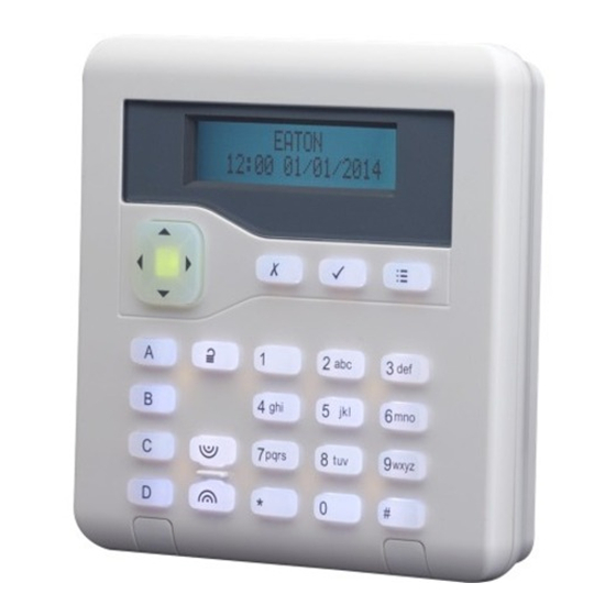
Menvier30 Before You Begin i-kp01 Controls and Displays 1. Central keyhole. 1. LCD display (2 x 20 characters). 2. Rear tamper shroud. 2. Programming keys. 3. Cable entry. 3. Navigation keys 4. Fixing holes. 4. Alert LEDs Figure 7 Keypad Rear Housing 5. -
Page 12: Key-K01/Kp01/Kpz01 Controls And Displays
Before You Begin Menvier30 KEY-K01/KP01/KPZ01 Controls and Displays 1. Central keyhole. 2. Fixing holes. 3. Cable entry. 4. Tamper block 1. LCD display Figure 11 Keypad Rear Housing 2. Programming keys. 3. Navigation keys. This key has built-in alert LEDs. -
Page 13: Expanders
Menvier30 Before You Begin 1. Tamper switch. 2. Sounder. 3. Connector for KEY-EP. 4. Sounder volume control. 5. Connector for control unit bus. 6. Jumpers for: 6a Addressing (not used in New Menvier control units). 6b LED functions and RS485 bus termination. - Page 14 Before You Begin Menvier30 1. Cable entry (also behind PCB). 2. Central keyhole. 3. PCB. 4. Relay card (i-rc01) connector. 5. Aux power. 6. Link to enable/disable front/rear tamper switch. 7. Lid tamper (rear tamper behind pcb). 8. Zone connectors 9.
- Page 15 Menvier30 Before You Begin 1. Cable entry (also behind PCB). 2. Antenna. 3. Central keyhole. 4. PCB. 5. Link to enable/disable front/rear tamper switch. 6. Lid tamper (rear tamper behind PCB). 7. Bus termination jumper. 8. Addressing button. 9. Fixing holes.
-
Page 16: Power Availability
Use one pair for data lines A and B. Use the other The following calculation shows a simplified pair for 12V and 0V. For optimum performance example: in an alarm system with an Menvier30 the voltage at the keypads and expanders should control unit, two i-kp01 keypads, and 15 wired be greater than 12V. -
Page 17: Bus Termination
Menvier30 Figure 18 Bus Wiring Configurations Note: only two expanders can have zones on a Menvier30. For star configurations the cable length from fit the termination jumper at the devices on control unit to the most distant bus device should the end of each arm. - Page 18 Device 3 Remote PSU Device 1 Device 2 Device 4 Control unit Figure 19. Connecting Remote Power Supply Units Note: Only two expanders can have zones on a Menvier30. Page 14...
-
Page 19: Installation
Menvier30 3. Installation Note: The installation steps listed below assume that you have already decided on the required number and location for all keypads, expanders and power supplies. Caution: Static Electricity Like many other electronic products, the control unit, keypads and expanders contain components that are sensitive to static electricity. -
Page 20: Installing The Lid/Back Tamper
Installation Menvier30 Figure 22 Insert Tabs Figure 24 Fit Securing Screw When the PCB is in place, connect the wires from the transformer to the 20Vac connector on the PCB (18 in Figure 3). Installing the Lid/Back Tamper Figure 25 Lid/Back Tamper Fit combined lid/back tamper bracket and switch Figure 23. -
Page 21: Step 2. Run Bus Cable
Menvier30 Installation Connect the lead from the switch to the back tamper connector on the PCB (see 4 in Figure 3). Step 2. Run Bus Cable Please read “Cabling Requirements on page 12. Step 3. Fit and Connect the Keypad(s) -
Page 22: Backlight Control For I-Kp01
Installation Menvier30 during the initial power up. See page 29 for In addition, the local keypad programming mode instructions. allows you to enable or disable the LEDs in the ABCD keys and the Navigation key. Backlight Control for i-KP01 It is possible to enter keypad programming mode... - Page 23 Menvier30 Installation To Leave Local Programming Mode 12 seconds after the last keypress. The action of and Save Changes the backlight depends on EITHER: the programming of the Press control unit (which must have Release 3 software or higher installed).
-
Page 24: Tone Volume - All Keypads
Installation Menvier30 Keep the prox reader cable clear of cables Opening the External Prox Reader supplying sounders or extension loudspeakers. To open the external prox reader (see Figure 30): Figure 32 shows the wiring connections at the 1. Undo the single retaining screw. -
Page 25: Connecting An Expander To The Bus
Menvier30 Installation Connecting an Expander to the Bus Anchor the mains cable with a strain-relief tie. There is a eye located near the mains cable entry Both wired and radio expanders provide a hole for this purpose (6 in Fig 2). -
Page 26: Two-Wire Closed Circuit Connections
Installation Menvier30 Fully Supervised Loop Connections Alarm Zone 0 Figure 39 shows the wiring connections for FSL Tamper Zone 0 zones on the control unit. Note that the resistance values shown are examples. Alarm Zone 1 Wired Expander Tamper Zone 1... - Page 27 Other values will not work (See System Options – Masking in the The allowed values for Alarm Contact/End of Line Menvier30/40/100/300 Engineering Guide). are the same as for the EXP-W10. Figure 42shows the wiring connections for FSL zones on a KEY-KPZ01.
-
Page 28: Step 7. Connect Wired Outputs
For 4-wire CC zones the polarity of this output see Changing the Polarity use the alarm contacts only and link the tamper of a Wired Output in the Menvier30/40/100/300 contacts together with a short length of wire. Engineering Guide. -
Page 29: Remote Loudspeakers (Optional)
Expanders provide connections for other FSL resistor combinations. one loudspeaker each. Do not connect another CC wiring Eaton’s Security Business does NOT loudspeaker in parallel. You may connect another recommend that you use CC wiring for this loudspeaker in series, but this will decrease the application. -
Page 30: Step 8. Connect The Internal Communicator
Communicator individual PSTNs provided in different countries, the approval does not, of itself, give an The Menvier30 has an internal communicator on unconditional assurance of successful operation its main PCB. This is an auto-dialling modem. on every PSTN network termination point. -
Page 31: Connecting The Telephone Line
Fit ADSL Filter If the telephone line is being shared by a broadband service then you should fit a broadband filter to the line. Eaton’s Security Business provides the ADSL01 filter that plugs onto pins provided for the purpose on the main circuit board of the control unit (see 5 on Figure 3). -
Page 32: Step 9. Fit A Plug-By Communicator
Note that the 7. Test communicator operation. output types shown in Figure 54 are the Factory default types. See the Menvier30/40/100/300 Note: You will need to speak to the ARC in order Engineering Guide for details on how to change to confirm that the communicator has worked the defaults. -
Page 33: Step 10. Fit And Connect Battery
Note that the alert LEDs round the navigation will not start the system. (See “Programming key glow red. This is because the control unit Before Installation” in the Menvier30/40/100/300 lid is off and the tamper is active. Engineering Guide.) 6. Press . -
Page 34: Transferring To Another Keypad
- System Options – Set Date & Time. See line of the display shows the first in the list of found and lost devices. Press to see any Menvier30/40/100/300 Engineering Guide for more information. other items in the list. -
Page 35: Important! Saving Changes
Installer Menu and disable the communicator by setting Communications – ARC the bottom line, for example: Reporting – Call Mode to “Disabled”. See the Menvier30/40/100/300 Engineering Guide for more information. You can press or to display the other sub-options. -
Page 36: Restoring Factory Defaults Only
Installation Menvier30 The control unit loads the factory default Access Codes and the Log. access codes: The display briefly shows: User 1=5678, Installer=1234. After a short pause the system starts a a tamper alarm and the display shows the Followed by: words “Please wait...”. -
Page 37: Program The System
Program the System Program the system to suit user requirements. Page 34 is a summary of the Installer Menu on the Menvier30. Please see the Menvier30/40/100/300 Engineering Guide for a more detailed description. Note: make sure that you allocate keypads correctly to wards. -
Page 38: Installer Menu
Menvier30 Installer Menu Part Set B Sounder on Account 1 DETECTORS/ DEVICES Name Siren on Connection Type Detectors Exit Mode Unconfirmed reset Rings to Answer Add/Del Detectors Settle time Confirmed reset Answer on one ring Program Zones Exit time HUA Confirm Time... - Page 39 Appears only if EXP-PSU is fitted. Appears only if Report Mode = Fast Format AND Confirmation Mode = Basic. Shows “None” on Menvier30. (If no communicator module is fitted). Must be activated by a Eaton’s Security Business External Support Manager.
-
Page 40: Maintenance
(allowing it to be used on another system). To replace a keypad: Use the Devices/Detectors-Wired Keypads-Replace Keypad option. This ensures that the replacement keypad will retain the programming of the old keypad. See the Menvier30/40/100/300 Engineering Guide for more details. Page 36... -
Page 41: Technical Specification
Product name Menvier30. (depending on the accuracy of Product 30 zone hybrid endstation with the mains supply frequency). Description remote keypads. Eaton’s Security Business. User Codes 50 (plus installer code) Manufacturer Remote controls 50 (one per user) Environmental Class II. -
Page 42: En50131-6 Ratings
10±0.5V to 13.8V Other voltage range : 12V Aux output 10±0.5V to 13.8V If you wish to connect the Menvier30 control unit voltage range: to a PC using the USB port then make sure that 12V Bell output 10±0.5V to 13.8V... -
Page 43: Compliance Statements
The Menvier30 is compliant with EN50130-5 760ES External Wireless sounder environmental class II. 9040UK-00 Speaker boxed The Menvier30 is suitable for use in systems Setting / Unsetting – Keypads designed to comply with PD 6662: 2010 at grade i-rk01 Radio Keypad i-kp01... - Page 44 Menvier30 www.coopersecurity.co.uk Product Support (UK) Tel: +44 (0) 1594 541978. Available between: 08: 30 to 17:00 Monday to Friday. Product Support Fax: (01594) 545401 email: techsupport@coopersecurity.co.uk Part Number 12375852 10/1/2014 Page 40...
Need help?
Do you have a question about the MENVIER30 and is the answer not in the manual?
Questions and answers