Flavel Windsor Installation, Maintenance And User Instruction
Hide thumbs
Also See for Windsor:
- Installation, maintenance & user instructions (44 pages) ,
- Installation, maintenance & user instructions (46 pages)
Table of Contents
Advertisement
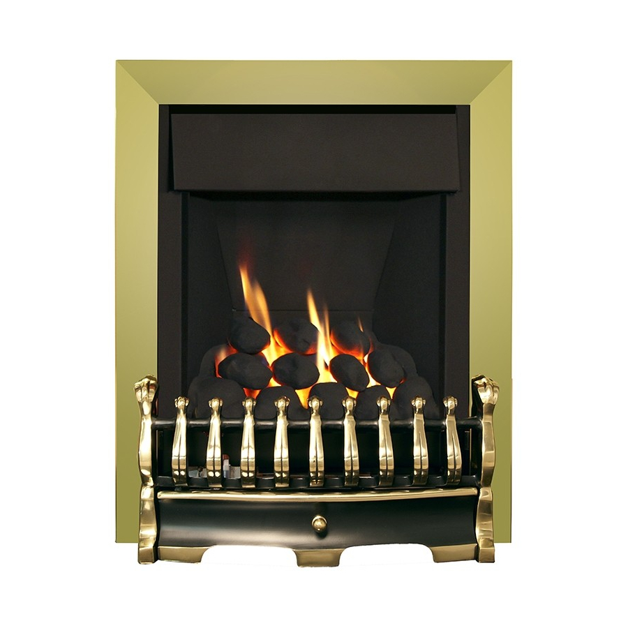
Windsor
DECORATIVE FUEL EFFECT GAS FIRE
Installation, Maintenance & User Instructions
Hand these instructions to the user
Model No's FSRC**MN, FSRP**MN & FSRD**MN are for use on
Natural Gas (G20) at a supply pressure of 20 mbar in G.B. / I.E.
** denotes trim and fret variant fitted to product
Supplied By www.heating spares.co Tel. 0161 620 6677
Advertisement
Table of Contents

Related Manuals for Flavel Windsor


Summary of Contents for Flavel Windsor
- Page 1 Windsor DECORATIVE FUEL EFFECT GAS FIRE Installation, Maintenance & User Instructions Hand these instructions to the user Model No’s FSRC**MN, FSRP**MN & FSRD**MN are for use on Natural Gas (G20) at a supply pressure of 20 mbar in G.B. / I.E.
-
Page 2: Table Of Contents
CONTENTS Section 1 Information and Requirements PAGE Appliance Information Conditions of Installation Flue and chimney suitability Fireplace / surround suitability Shelf position Chimney inspection Fire place opening / catchment space Fitting to Chair bricks Precast Flues Metal Flue boxes 1.10 Hearths 1.11 Spillage Monitoring System... -
Page 3: Information And Requirements Page
SECTION 1 INFORMATION AND REQUIREMENTS APPLIANCE INFORMATION Model FSRC**MN, FSRP**MN & FSRD**MN ** denotes trim & fret variant of product Gas Type Main injector (1 off) Size 440 Burner Type Aeromatic Self Vitiating Tubular Burner Max. Gross Heat Input : 6.5 kW Min. -
Page 4: Conditions Of Installation
INSTALLATION REQUIREMENTS CONDITIONS OF INSTALLATION It is the law that all gas appliances are installed only by a CORGI Registered Installer, in accordance with these installation instructions and the Gas Safety (Installation and Use) Regulations 1998 as amended. Failure to install appliances correctly could lead to prosecution. -
Page 5: Fireplace / Surround Suitability
FIREPLACE / SURROUND SUITABILITY The fire must only be installed on a hearth it must not be installed directly onto carpet or other combustible floor materials. The fire is suitable for fitting to non-combustible fire place surrounds and propri- etary fire place surrounds with a temperature rating of at least 150 o c. If a heating appliance is fitted directly against a wall without the use of a fire surround or fire place all combustible material must be removed from behind the trim. -
Page 6: Fire Place Opening / Catchment Space
There must be no leakage of smoke through the structure of the chimney during or after the smoke pellet test and it is important to check inside upstairs rooms adjacent to the chimney / flue. Check the chimney pot / terminal and general condition of the brickwork or masonry. - Page 7 Table A - Installation Depth Requirements for a Flavel Windsor being installed into a brick built chimney, requiring 12.0 litres of debris collection volume (fig. 2). Opening Width (mm) Minimum Depth Required (mm) 330 (minimum opening width) 440 (maximum opening width) For example, if the appliance was to be fitted into a 400mm wide opening, the depth required would be 135mm.
-
Page 8: Fitting To Chair Bricks
1.7 FITTING TO FIREPLACES WITH EXISTING CHAIRBRICKS AND CONVENTIONAL BRICKBUILT CHIMNEYS This appliance is suitable for use in fireplaces fitted with an existing chairbrick without the need for removal of the chairbrick, providing the minimum depth of the fireplace exceeds 175mm. If the depth is less than 175mm then the chairbrick must be removed. -
Page 9: Hearths
1.10 HEARTHS This appliance must only be installed on to a concrete or non-combustible hearth. The hearth material must be a minimum thickness of 12mm with the top surface at least 50mm above the floor. The hearth must be fitted symmetrically about the fire opening and have a minimum width of 760mm and a minimum projection of 300mm forwards from the fire opening. -
Page 10: Installation Of Fire
SECTION 2 INSTALLATION OF FIRE UNPACKING THE FIRE Carefully lift the fire out of the carton. Remove the loose item packaging carefully from the front of the appliance. Check the contents as listed :- Packing Check List - Coal Fuelbed Models 1off Fire box / burner assembly 1off... - Page 11 Proceed as follows :- Remove the two screws at the bottom of the control panel. See fig. 3 below Fig. 3 2 burner retaining screws The base of the burner unit can now be lifted, lift the two retaining tabs on the burner brackets from the back of the firebox, allowing the burner to be removed.
- Page 12 Whilst the fire box is still in position, decide which side the gas supply is to enter the fire from. If concealed pipe work is required plan the pipe run to enter the fire box through one of the openings in the sides or rear of the fire box below the fuelbed support panel and connect to the isolating / inlet elbow.
- Page 13 There is a choice of methods of fixing the firebox which are provided to enable the installer to deal with any type of installation. The preferred method of fixing which is suitable for almost all situations is the cable fixing method which is described in the following section in detail. The fire may be secured using the cable method as described below, or alternatively, in installations where the cable method is not suitable (eg.
- Page 14 Position the fire carefully on the (protected) surface of the hearth and reach into the fire opening. Thread each of the cables vertically downwards through the pair of fixing eyes on the same side of the fire. Thread the free end of the cables through the corresponding circular hole on each side of the lower rear of the fire.
-
Page 15: Gas Tightness And Burner Pressure
Before making the final gas connection, thoroughly purge the gas supply pipework to remove all foreign matter, otherwise serious damage may be caused to the gas control valve on the fire. The other firebox fixing method is as follows :- In installations where the cable method is not suitable (e.g. -
Page 16: Assembling Fuel Bed And Commissioning
continue to hold the control knob for a few seconds then turn to the full- on position. Check that the gas pressure is 20.0 mbar (+/- 1.0mbar) 8.0 in w.g.(+/- 0.4 in w.g.) Turn off the fire, remove the manometer and refit the pressure test point screw. - Page 17 Position the front row of four loose coals along behind the first row of coals, ensuring that the flame paths as indicated are not interupted. See Fig. 11 below Fig. 11 Fit the remaining three coals onto the ribs in the fuelbed as shown below, ensuring that the rear flame paths as indicated are not interupted See Fig.
-
Page 18: Assembling The Ceramics And Fuelbed (Pebble Models)
The exact position and fit of the coals may be finely adjusted to give the best appearance. Warning : Use only the coal set supplied with the fire. When replacing the coals remove the old coals and discard them. Fit a complete set of coals of the correct type. - Page 19 Position the front row of four large loose pebbles along behind the first row of pebbles, ensuring that the flame paths as indicated are not interupted. See Fig. 14 below Fig. 14 Beige Pebbles to be Positioned as shown Fit the three small pebbles onto the ribs in the fuelbed as shown below, ensuring that the rear flame paths as indicated are not interupted.
-
Page 20: Assembling The Ceramics And Fuelbed (Driftwood Models)
ASSEMBLING THE FUEL-BED - Driftwood Fuelbed Model Place the fuelbed base centrally on to the fuelbed support and push fully backwards to the rear face of the fibre boards Make sure that the fuelbed base is located centrally in the fire box. See Fig. 16 below Fig. - Page 21 Position the piece of driftwood with the letter “B” stamped onto the bottom face of it in the position at the centre of the fuelbed matrix. Ensure the positioning grooves as shown are on the top face of the piece of driftwood. See Fig. 18 below. Fig.
- Page 22 Position the piece of driftwood with the letter “D” stamped onto the bottom face of it in the position at the right-hand side of the fuelbed matrix. Ensure this piece of driftwood is located into the groove in the front right hand side of the fuelbed matrix . See Fig. 20 below. Fig.
- Page 23 Position the piece of driftwood with the letter “F” stamped onto the bottom face of it in the across the centre of the driftwood pieces “A”, “B” & “C”. Ensure this piece of driftwood is located into the groove’s on the top face of driftwood pieces A, B &...
- Page 24 Warning : Use only the driftwood set supplied with the fire. When replacing the driftwood remove the old driftwood pieces and discard them. Fit a complete set of driftwood pieces of the correct type. Do not fit additional driftwood or any driftwood pieces other than a genuine replacement set. This appliance uses fuel effect pieces containing Refractory Ceramic Fibres (R.C.F.), which are man-made vitreous silicate fibres.
- Page 25 IMPORTANT INFORMATION REGARDING FUELBED POSITION ON COAL, PEBBLE & DRIFTWOOD MODELS. Before continuing with the installation, ensure that the fuelbed is located behind the locating tabs as shown below in Fig. 24, not on top of the locating tabs as shown in Fig. 25 Fig.
-
Page 26: Fitting The Trim
The exact position and fit of the pebbles may be finely adjusted to give the best appearance. Warning : Use only the pebble set supplied with the fire. When replacing the pebbles remove the old pebbles and discard them. Fit a complete set of pebbles of the correct type. -
Page 27: Lighting The Appliance
LIGHTING THE APPLIANCE (All models) Turn on the gas isolation tap. Depress the control knob and turn anti-clockwise to the position marked ignition / low rate. Hold in the control knob for a few seconds to purge the pipe work. Continue to hold-in the control knob and press the igniter button. - Page 28 If there is an extractor fan fitted any where in the vicinity of the appliance, or in adjacent rooms the spillage test should be repeated with the fan running on maximum and all interconnecting doors open. After ensuring that the fire is safe to use it should be left on high position to fully warm up.
-
Page 29: Maintenance
Servicing Notes Servicing should be carried out annually by a competent person such as a CORGI registered engineer. This is a condition of the Flavel guarantee schemes. The service should include visually checking the chimney and fire opening for accumulations of debris and a smoke test to check for a positive up-draught in the chimney. -
Page 30: Removal Of The Control Tap
Replacement of any other parts must be carried out by a competent person such as a CORGI registered gas installer. The part numbers of the main replaceable parts are as follows, these are available from your local Flavel Stockist, whose details can be found on the CFM Europe website, in the “stockist” section. -
Page 31: Conditions Of Installation / About Your New Gas Fire
SECTION FIVE - USER INSTRUCTIONS 5.1 Installation Information Conditions of Installation It is the law that all gas appliances are installed only by a competent (e.g. CORGI Registered) Installer, in accordance with the installation instructions and the Gas Safety (Installation and Use) Regulations 1998. Failure to install appliances correctly could lead to prosecution. - Page 32 About your Flavel Windsor The Flavel Windsor range of coal, pebble & driftwood fuel-bed gas fires incorporates a unique and highly developed fuel bed which gives the realism of a loose coal or pebble layout combined with realistic flames and glow. The use of durable ceramic material in the construction of the fuel-bed components ensures long and trouble free operation.
-
Page 33: 5.2 Operating The Fire
The ceramic fuel-bed remains hot for a considerable period after use and sufficient time should be allowed for the fire to cool before cleaning etc. The fire must only be operated with the trim and fret supplied with the fire. 5.2 Operating the Fire The controls are located behind the ashpan cover which is situated below the fret or contemporary ashpan cover. -
Page 34: Assembling The Coal Fuelbed
ASSEMBLING THE FUEL-BED - Coal Fuelbed Model Place the fuelbed base centrally on to the fuelbed support and push fully backwards to the rear face of the fibre boards Make sure that the fuelbed base is located centrally in the fire box. See Fig. 26 below. Fig. - Page 35 Fit the remaining three coals onto the ribs in the fuelbed as shown below, ensuring that the rear flame paths as indicated are not interupted See Fig. 28 below. Fig. 28 The exact position and fit of the coals may be finely adjusted to give the best appearance.
-
Page 36: Assembling The Pebble Fuelbed
ASSEMBLING THE FUEL-BED - Pebble Fuelbed Model Place the fuelbed base centrally on to the fuelbed support and push fully backwards to the rear face of the fibre boards Make sure that the fuelbed base is located centrally in the fire box. See Fig. 29 below Fig. - Page 37 Fit the three small pebbles onto the ribs in the fuelbed as shown below, ensuring that the rear flame paths as indicated are not interupted. See Fig. 31 below. Fig. 31 Beige pebbles to be positioned as indicated The exact position and fit of the pebbles may be finely adjusted to give the best appearance.
-
Page 38: Assembling The Driftwood Fuelbed
ASSEMBLING THE FUEL-BED - Driftwood Fuelbed Model Place the fuelbed base centrally on to the fuelbed support and push fully backwards to the rear face of the fibre boards Make sure that the fuelbed base is located centrally in the fire box. See Fig. 32 below Fig. - Page 39 Position the piece of driftwood with the letter “B” stamped onto the bottom face of it in the position at the centre of the fuelbed matrix. Ensure the positioning grooves as shown are on the top face of the piece of driftwood. See Fig. 34 below. Fig.
- Page 40 Position the piece of driftwood with the letter “D” stamped onto the bottom face of it in the position at the right-hand side of the fuelbed matrix. Ensure this piece of driftwood is located into the groove in the front right hand side of the fuelbed matrix . See Fig. 36 below. Fig.
- Page 41 Position the piece of driftwood with the letter “F” stamped onto the bottom face of it in the across the centre of the driftwood pieces “A”, “B” & “C”. Ensure this piece of driftwood is located into the groove’s on the top face of driftwood pieces A, B &...
- Page 42 Warning : Use only the driftwood set supplied with the fire. When replacing the driftwood remove the old driftwood pieces and discard them. Fit a complete set of driftwood pieces of the correct type. Do not fit additional driftwood or any driftwood pieces other than a genuine replacement set. This appliance uses fuel effect pieces containing Refractory Ceramic Fibres (R.C.F.), which are man-made vitreous silicate fibres.
- Page 43 IMPORTANT INFORMATION REGARDING FUELBED POSITION ON BOTH COAL, PEBBLE & DRIFTWOOD MODELS. Before continuing with the installation, ensure that the fuelbed is located behind the locating tabs as shown below in Fig. 40, not on top of the locating tabs as shown in Fig. 41 Fig.
-
Page 44: Cleaning The Fire
5.6 Cleaning - WARNING Before attempting any cleaning operation ensure that the fire has been allowed to fully cool. The Brass fret that was supplied with the fire (dependent upon model chosen) is real brass and therefore will discolour with use and should be cleaned with a proprietory metal polish. -
Page 45: Cfm Europe Ltd
Removal / Re-fitting of the Fret & Ashpan Cover Remove the fret & ashpan cover from the packaging. Place fret up to the front radiused section of the fuelbed, taking care not to move coal positions. Place ashpan cover under fret assembly and centralise. NOTE : Some models in this range are not supplied with a fret from the factory, therefore please consult your local retailer for fitting... - Page 46 Supplied By www.heating spares.co Tel. 0161 620 6677...
- Page 47 Supplied By www.heating spares.co Tel. 0161 620 6677...
- Page 48 Supplied By www.heating spares.co Tel. 0161 620 6677...
Need help?
Do you have a question about the Windsor and is the answer not in the manual?
Questions and answers