Table of Contents

Related Manuals for Maxview Crank Up B2590/65


Summary of Contents for Maxview Crank Up B2590/65
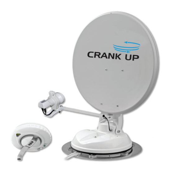
- Page 1 B2590/65 & B2590/85 Crank Up Installation & operating instructions UK contact: Helpline: +44 (0)1553 811000 Email: support@maxview.co.uk Web: www.maxview.co.uk Maxview reserve the right to change specifications without prior notice 9111410 Iss 3...
-
Page 2: Table Of Contents
All instructions and models are subject to change. In accordance with policy of progressive product, the company reserve the right to alter specifications. Copyright© these instructions are the sole property of Maxview Ltd and may not be reproduced. Please keep these instructions safe for future reference. -
Page 3: Safety Precautions
Failure to follow all instructions listed below may result in electric shock, fire and/or serious injury. Maxview declines all responsibility in the event of incident or accident if they are due to a non observation of the installation instructions or the way the product is used. -
Page 4: Application Example
> Deburrer/Round File/Emery paper > Power Drill > Conduit (recommend method for securing cables) > Hacksaw > No.2 Phillips screwdriver *Maxview recommends the following adhesives: > Weather Resistant Elastic Adhesive* and Applicator gun > Sikaflex®-512 Caravan > Surface Cleaner > Geocel® Geobond HM >... -
Page 5: Selecting An Installation Location
> Check for obstructions such as roof lights and vents. > Check for electrical cables beneath screw fixing points. > Check the ‘F’ cables will reach satellite receiver (Maxview can supply extended cables). > Do not allow the dish to overhang the edge of the vehicle >... -
Page 6: Attaching Antenna Mount Plate
Attaching Antenna Mount Plate & LNB Park Plate: Remove antenna unit from wooden transit packaging Remove mounting plate from Antenna Unit by removing 6 x M6 nuts using 10mm spanner Clean roof, Mounting Plate and LNB Park Plate in accordance with adhesive manufacturer’s guidelines Mark a centre line for the antenna making sure dish will not overhang vehicle Align notches on plate with centre line Mark the position of 6 screw fixing holes and centre hole... - Page 7 7 x No. 10 screws (large) Place a small amount of adhesive into each pilot hole before screwing plate to roof. Wipe off excess adhesive with a cloth. Note: > Follow manufacturer’s instructions when applying adhesive. Do not travel until adhesive has cured noting that curing times vary with weather conditions.
-
Page 8: Installing Cables
See below for Cable Entry Cover instructions Application example: Use extra Cable Entry Cover to route 2nd Sat feed to a different location. Available to order from Maxview MXL018 Note: LNB image shows different model. Direction of travel ... -
Page 9: Installing Handle
Installing the handle: Note: LNB image shows different model. Push the aluminium tube into the plastic coupler and insert into the antenna unit through the hole in the ceiling With the plastic coupler pushed up tight to the ceiling, mark the aluminium tube along all four sides. Drilled hole Aluminium tube Coupler... - Page 10 40mm Cut the 20mm square tube with a hacksaw. Now mark and cut the 4mm spindle so that it is Make the cut so that the line is left on the 40mm longer than the tube. discarded part of the tube. With the Coupler Bush aligned to the rear of the vehicle insert the Tube and Coupler Bush through the ceiling hole and into the antenna unit.
- Page 11 Place the Base Plate over the Coupler Bush. Point Take the Dish Direction Unit and turn the azimuth the arrow to the rear of the vehicle. Mark the lock lever to the red position to release the brake. four fixing holes. Drill four 2.5mm pilot holes or use a bradawl.
-
Page 12: Attaching Satellite Dish To Unit
Attaching the Satellite Dish to the Antenna Unit Ensure Antenna Unit is free from obstacles. Turn the azimuth lock lever to the green position (locked for travel) Elevate the antenna to 25 degrees (25 turns = 25 degrees) Azimuth Lock is Green - LOCKED for travel Wind handle clockwise 25 turns to reach 25 degrees Elevation Window... -
Page 13: Finding A Satellite
Finding a Satellite Before starting check there is a clear line of sight to the southern sky. All television broadcasting satellites have a geostationary orbit which means their location is fixed above the earth’s equator. Satellites also have a limited range of transmission so use the Zone maps included in the appendix to check your location is suitable for reception. - Page 14 Now Turn the Azimuth Lock Lever to the RED position to disengage the brake and turn Dish Direction Unit to a South Easterly direction as indicated by the compass. Slowly scan from South East to South whilst checking for a picture on the Television. If no satellite is found adjust the elevation by 2 degrees and repeat the scan.
-
Page 15: Lowering Antenna
Lowering antenna: Arrows align Align Dish Direction for travel Pointer to Base plate Elevation Antenna Down home position Lock Azimuth Lock Rotate the Dish Direction Unit until it aligns with Slowly turn the handle until elevation indicator the Base Plate and Lock Azimuth (green). fully shows the home position and you feel some park resistance. -
Page 16: Skew Adjustment
Skew adjustment: Astra 2 - 28.2° Skew adjustment is required when signal strength is weak at the limit of a given satellites’ reception area. It involves adjusting the angle of the LNB on the roof mounted antenna unit. Caution: Follow general safety advice on page 3 when adjusting Antenna Unit. -
Page 17: Warranty
Maxview is responsible for the cost of a replacement part if the original part is determined to be defective under the terms of guarantee. The customer is responsible for the cost of replacement parts after three years. -
Page 18: Specifications
Specifications: Operating: Low stream line profile, only 17cm in park position Power: Powering: Manual operation no power required System: Elevation Range: 10º to 70º Azimuth Range: 380º Skew Angle: ±45º Cable Type: CAI approved 100 coaxial cable UV Protection: All external plastic parts are UV stabilised Testing: Fully weatherproof and watertight construction System has passed extensive water ingress test... -
Page 19: Quick Reference Table
Quick reference table: Your locations - Add your favourite locations for quick reference for future use Satellite Location Elevation Number Notes (degrees) of turns Astra 28.2E King’s Lynn Crank Up Manufacturer Location Page 19...
Need help?
Do you have a question about the Crank Up B2590/65 and is the answer not in the manual?
Questions and answers