Table of Contents
Advertisement
Quick Links
Advertisement
Table of Contents

Related Manuals for Maxview Connect Sky Q MXL028


Summary of Contents for Maxview Connect Sky Q MXL028
- Page 1 Installation, Satellite Information & Fault Finding Booklet 1 of 2 MXL028/65Q/85Q Connect Sky Q™ & Auto Skew UK contact: Helpline: +44 (0)1553 811000 Email: support@maxview.co.uk Web: www.maxview.co.uk Maxview reserve the right to change specifications without prior notice 9111420SKYQ Iss 3...
-
Page 2: Table Of Contents
All instructions and models are subject to change. In accordance with policy of progressive product, the company reserve the right to alter specifications. Copyright© these instructions are the sole property of Maxview Ltd and may not be reproduced. Please keep these instructions safe for future reference. - Page 3 Failure to follow all instructions listed below may result in electric shock, fire and/or serious injury. Maxview declines all responsibility in the event of incident or accident if they are due to a non observation of the installation instructions or the way the product is used.
-
Page 4: Installation
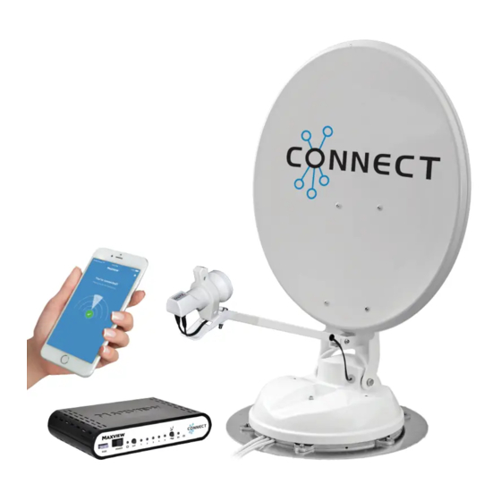
INSTALLATION Application Example A. Antenna The Antenna is mounted to the roof. It uses electric motors to scan for satellite signals. The twin variant has 3 cable connections; 1 for controlling the motors and 2 satellite signal cables from the twin LNB. B. -
Page 5: Connections & Features
> Power Drill > Flylead (for connection to satellite receiver) > No.2 Phillips screwdriver > Weather Resistant Elastic Adhesive* and Applicator gun *Maxview recommends the following adhesives: > Surface Cleaner > Sikaflex®-512 Caravan > 10mm spanner > Geocel® Geobond HM >... -
Page 6: Selecting An Installation Location
> Check for electrical cables beneath screw fixing points > Check Antenna Unit cables will reach Control Box (Maxview can supply extended cables). > Do not allow the dish to overhang the edge of the vehicle > Clearance around antenna system when in use is shown with reference... -
Page 7: Attaching Antenna Mount Cover
Attaching Antenna Mount Plate & LNB Park Plate Remove Antenna Unit from wooden transit packaging Remove mounting plate from Antenna Unit by removing 6 x M6 nuts using 10mm spanner Clean roof, Mounting Plate and LNB Park Plate in accordance with adhesive manufacturer’s guidelines Mark a centre line for the antenna making sure dish will not overhang vehicle Align notches on plate with centre line Mark the position of 6 screw fixing holes... -
Page 8: Electrical Installation
Electrical Installation Whilst the adhesive is curing prepare the electrical connections for the Control Box. The Control Box requires a permanent 12V supply and a secondary 12V supply that provides power when the engine of the vehicle is running. Note: the brake light circuit is not suitable. It is recommended to create a new circuit direct to the battery using a minimum cable cross sectional area of 2.5mm and an inline fuse of 5A. -
Page 9: Attaching Antenna Unit To Mount Plate
2nd cable to route 2nd Sat feed to a entry plate. different location. Available to order from Maxview MXL018 Direction of travel (front of vehicle) Note: To prevent trip hazards it is recommended that cables are concealed in PVCu conduit (not supplied) where access is required to the roof of the vehicle. -
Page 10: Installing Cable Entry Plate
Installing Cable Entry Cover Cable Plan your installation carefully Drill a 32mmø hole in roof Prepare surface for adhesion Hole location Apply sealant as shown in A,B,C tabs (we recommend Sikaflex-512 Caravan)* Top hat Position top hat Position cable entry cover Wipe excess sealant with a dry cloth Vehicle roof Applying sealant example:... -
Page 11: Connection Diagram
Connection diagram: SAT IN 1 (Cable marked V) SAT 2 (Cable marked H) SAT IN 2 SKY Q™ Receiver Splitter 5A Fuse Not required Ignition Attach Satellite Dish to Antenna Unit Ensure Antenna Unit is free from obstacles Press installation button on reverse of Control Box to elevate antenna. -
Page 12: Testing Bluetooth Connectivity & Installing
Explain function of app and Control Box to customer. Date Fitted:..............Was a Software Update Required?: YES/NO Serial Number:............If Yes, Composer Version Number:......Control Box Number:..........Signed:............... Installer Name:............Maxview recommend the above is completed and signed off prior to hand over to the customer. Page 12... -
Page 13: Satellite Information
SATELLITE INFORMATION Finding a Satellite Before starting, check there is a clear line of sight to the southern sky. All television broadcasting satellites have a geostationary orbit which means their location is fixed above the earth’s equator. Satellites also have a limited range of transmission so use the Zone maps included in the appendix to check your location is suitable for reception. -
Page 14: Skew Adjustment
If you have any further questions regarding manual or automatic skew adjustment, please contact Maxview Customer Services on +44 (0)1553 811000 or visit www.maxview.co.uk. Astra 2 - 28.2° Astra 1 - 19.2°... -
Page 15: Fault Finding
FAULT FINDING On Screen Error Modes If your portable device is paired with the control box, error messages will be visible on the App. In any case, the error modes will also be visible on the control box. Elevation Error Azimuth Error Activated when the rotation Activated when the elevation... -
Page 16: Control Box Error Modes
Control Box Error modes: Solid red A. No SAT found. If searching and no satellite found the ‘flashing green’ LED will go solid RED After 5 seconds the dish will then move to park position. Flashes green Solid red B. No SAT found - system parked. - Page 17 All solid red D. Ignition mode parked. When system parked during ignition mode all the SAT LED’s stop flashing green and ALL 5 LED’s go solid RED. During Ignition mode ALL control buttons have no function (locked). Once ‘Ignition off’ last satellite found LED start to flash and ready to search (keys active again). Solid orange E.
-
Page 18: General Faults & Faqs
Check fuse rating is 4A • Check antenna unit is not obstructed • Contact Maxview Customer Service +44 01553 811000 Antenna searching correctly but not locating a satellite • After 15 minutes of searching, the satellite dish will return to the park position. -
Page 19: Portable Connectivity Troubleshooting
Portable Connectivity Troubleshooting Unable to find device during set up • Ensure control box in turned on • Ensure device Bluetooth™ is switched on • Ensure you are within range of Control box. If you are unsure we suggest moving next to the control box No software found 1. -
Page 20: Ignition
Connecting to a Satellite Receiver The satellite cables must connect to the Control Box. The Control Box will then output this signal through the F connector marked ‘RECEIVER’. In order for the satellite signal to pass through the Control Box the power must be Power Consumption The Connect has been designed to minimise power consumption. -
Page 21: Year Guarantee
A guarantee authorisation must be obtained from Maxview prior to work commencing. c) Maxview is responsible for the cost of a replacement part if the original part is determined to be defective under the terms of the guarantee. -
Page 22: Environment
Environment: Information for users on collection and disposal of old electrical equipment and used batteries These symbols on the products, packaging, and/or accompanying documents mean that used electrical and electronic products and batteries should not be mixed with general household waste. For proper treatment, recovery and recycling of old products and used batteries, please take them to applicable collection points, in accordance with your national legislation and the Directives 2002/96/EC and 2006/66/EC. - Page 23 Notes Page 23...
-
Page 24: Specifications
Software Updates: Requires 3G, 4G or WIFI connection Maxview Ltd is a member of the Bluetooth™ special interest group. The Connect is licensed to use Bluetooth™ technology. CE Declaration of Conformity. The Connect Satellite Antenna has been designed, constructed and marketed in compliance with safety requirements of EEC Directive 2006/95/EEC (Low voltage) and requirements of EMC Directive 2004/108/EEC.
Need help?
Do you have a question about the Connect Sky Q MXL028 and is the answer not in the manual?
Questions and answers