
Related Manuals for Edge-Core ECS3610-28T


Summary of Contents for Edge-Core ECS3610-28T
- Page 1 ECS3610-28T 28-Port Layer 3 Installation Guide Fast Ethernet Switch www.edge-core.com...
- Page 3 N S T A L L A T I O N U I D E ECS3610-28T FAST ETHERNET SWITCH Layer 3 Switch with 24 10/100BASE-TX (RJ-45) Ports, 2 Gigabit Combination Ports (RJ-45/SFP), and 2 SFP Slots ECS3610-28T E122010-MW-R01 150200000125A...
-
Page 5: Compliances And Safety Statements
OMPLIANCES AND AFETY TATEMENTS FCC - C LASS This equipment has been tested and found to comply with the limits for a Class A digital device, pursuant to part 15 of the FCC Rules. These limits are designed to provide reasonable protection against harmful interference when the equipment is operated in a commercial environment. - Page 6 OMPLIANCES AND AFETY TATEMENTS CE M (EEC) ECLARATION OF ONFORMANCE FOR AFETY This information technology equipment complies with the requirements of the Council Directive 89/336/EEC on the Approximation of the laws of the Member States relating to Electromagnetic Compatibility and 73/23/EEC for electrical equipment used within certain voltage limits and the Amendment Directive 93/ 68/EEC.
- Page 7 OMPLIANCES AND AFETY TATEMENTS AFETY OMPLIANCE Warning: Fiber Optic Port Safety When using a fiber optic port, never look at the transmit laser while it is powered on. Also, never look directly at the CLASS I fiber TX port and fiber cable ends when they are powered LASER DEVICE Avertissment: Ports pour fibres optiques - sécurité...
- Page 8 OMPLIANCES AND AFETY TATEMENTS OWER AFETY Please read the following safety information carefully before installing the switch: Installation and removal of the unit must be carried out by qualified WARNING: personnel only. The unit must be connected to an earthed (grounded) outlet to comply with ◆...
- Page 9 OMPLIANCES AND AFETY TATEMENTS Power Cord Set U.S.A. and Canada The cord set must be UL-approved and CSA certified. The minimum specifications for the flexible cord are: - No. 18 AWG - not longer than 2 meters, or 16 AWG. - Type SV or SJ - 3-conductor The cord set must have a rated current capacity of at least 10 A...
- Page 10 OMPLIANCES AND AFETY TATEMENTS La prise secteur doit se trouver à proximité de l’appareil et son accès doit ◆ être facile. Vous ne pouvez mettre l’appareil hors circuit qu’en débranchant son cordon électrique au niveau de cette prise. L’appareil fonctionne à une tension extrêmement basse de sécurité qui est ◆...
- Page 11 OMPLIANCES AND AFETY TATEMENTS Bitte unbedingt vor dem Einbauen des Switches die folgenden Sicherheitsanweisungen durchlesen: Die Installation und der Ausbau des Geräts darf nur durch WARNUNG: Fachpersonal erfolgen. Das Gerät sollte nicht an eine ungeerdete Wechselstromsteckdose ◆ angeschlossen werden. Das Gerät muß an eine geerdete Steckdose angeschlossen werden, welche ◆...
- Page 12 OMPLIANCES AND AFETY TATEMENTS ARNINGS AND AUTIONARY ESSAGES This product does not contain any serviceable user parts. ARNING Installation and removal of the unit must be carried out by ARNING qualified personnel only. When connecting this device to a power outlet, connect the ARNING field ground lead on the tri-pole power plug to a valid earth ground line to prevent electrical hazards.
-
Page 13: C Ompliances And S Afety S Tatements
OMPLIANCES AND AFETY TATEMENTS ND OF RODUCT This product is manufactured in such a way as to allow for the recovery and disposal of all included electrical components once the product has reached the end of its life. ANUFACTURING ATERIALS There are no hazardous nor ozone-depleting materials in this product. - Page 14 OMPLIANCES AND AFETY TATEMENTS – 14 –...
-
Page 15: About This Guide
BOUT UIDE URPOSE This guide details the hardware features of the switch, including the physical and performance-related characteristics, and how to install the switch. UDIENCE The guide is intended for use by network administrators who are responsible for installing and setting up network equipment; consequently, it assumes a basic working knowledge of LANs (Local Area Networks). - Page 16 BOUT UIDE EVISION ISTORY This section summarizes the changes in each revision of this guide. 2010 R ECEMBER EVISION This is the first revision of this guide. – 16 –...
-
Page 17: Table Of Contents
ONTENTS OMPLIANCES AND AFETY TATEMENTS BOUT UIDE ONTENTS ABLES IGURES NTRODUCTION Overview Description of Hardware ETWORK LANNING Introduction to Switching Application Examples Application Notes NSTALLING THE WITCH Selecting a Site Ethernet Cabling Equipment Checklist Mounting Installing an Optional SFP Transceiver Connecting to a Power Source Connecting to the Console Port AKING... - Page 18 ONTENTS Fiber Optic SFP Devices Connectivity Rules Cable Labeling and Connection Records ROUBLESHOOTING Diagnosing Switch Indicators Power and Cooling Problems Installation In-Band Access ABLES Twisted-Pair Cable and Pin Assignments Fiber Standards PECIFICATIONS Physical Characteristics Switch Features Management Features Standards Compliances LOSSARY NDEX –...
-
Page 19: Tables
ABLES Table 1: Supported SFP Transceivers Table 2: Port Status LEDs Table 3: System Status LEDs Table 4: Serial Cable Wiring Table 5: Maximum 1000BASE-T Gigabit Ethernet Cable Length Table 6: Maximum 1000BASE-SX Gigabit Ethernet Cable Lengths Table 7: Maximum 1000BASE-LX Gigabit Ethernet Cable Length Table 8: Maximum 1000BASE-LH Gigabit Ethernet Cable Length Table 9:... - Page 20 ABLES – 20 –...
-
Page 21: Figures
IGURES Figure 1: Front and Rear Panels Figure 2: Port LEDs Figure 3: System LEDs Figure 4: Power Supply Sockets Figure 5: Collapsed Backbone Figure 6: Making VLAN Connections Figure 7: IP Routing for Unicast Traffic Figure 8: RJ-45 Connections Figure 9: Attaching Brackets for Rack Mounting Figure 10:... - Page 22 IGURES – 22 –...
-
Page 23: Introduction
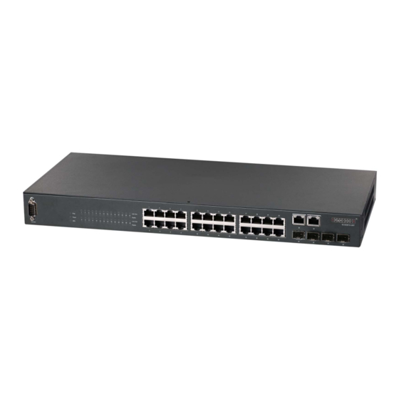
NTRODUCTION VERVIEW This Fast Ethernet Switch is an intelligent multilayer switch (Layer 2/3/4) with 24 10/100BASE-TX ports, two 10/100/1000BASE-T combination ports that are shared with SFP transceiver slots (Ports 25-26), and two SFP slots. This switch can easily tame your network with full support for Spanning Tree Protocol, Multicast Switching, Virtual LANs, and IP routing. - Page 24 | Introduction HAPTER Overview WITCH RCHITECTURE This Fast Ethernet switch employs a wire-speed, non-blocking switching fabric. This permits simultaneous wire-speed transport of multiple packets at low latency on all ports. The switch also features full-duplex capability on all ports, which effectively doubles the bandwidth of each connection. For communications between different VLANs, this switch uses IP routing.
-
Page 25: Description Of Hardware
| Introduction HAPTER Description of Hardware ESCRIPTION OF ARDWARE RJ-45 P ORTS The switch contains 24 100BASE-TX RJ-45 ports that operate at 10/100 Mbps, half or full duplex (Ports 1-24), and two 1000BASE-T RJ-45 ports that operate at 10 Mbps or 100 Mbps, half or full duplex, or at 1000 Mbps, full duplex (Ports 25- 26 with no SFP transceiver inserted). -
Page 26: Table 1: Supported Sfp Transceivers
| Introduction HAPTER Description of Hardware Table 1: Supported SFP Transceivers Media Standard Fiber Diameter Wavelength (nm) Maximum Distance (microns) 1000BASE-SX 50/125 700 m 62.5/125 400 m 1000BASE-LX 50/125 1300 550 m 62.5/125 1300 550 m 9/125 1300 10 km 1000BASE-LH 9/125 1310... -
Page 27: Figure 2: Port Leds
| Introduction HAPTER Description of Hardware ORT AND YSTEM TATUS The switch includes a display panel for key system and port indications that simplify installation and network troubleshooting. The LEDs, which are located on the front panel for easy viewing, are shown below and described in the following tables. -
Page 28: Table 2: Port Status Leds
| Introduction HAPTER Description of Hardware Table 2: Port Status LEDs Condition Status 10/100BASE-TX Ports 21-24 LNK/Act On/Flashing Amber Port has established a valid 10 Mbps network (Link/Activity) connection. Flashing indicates activity. On/Flashing Green Port has established a valid 100 Mbps network connection. -
Page 29: Table 3: System Status Leds
| Introduction HAPTER Description of Hardware Figure 3: System LEDs System Status LEDs Table 3: System Status LEDs Condition Status Diag Flashing Green System self-diagnostic test in progress. Green System self-diagnostic test successfully completed. Amber System self-diagnostic test has detected a fault. Green Internal power is operating normally. -
Page 30: Figure 4: Power Supply Sockets
| Introduction HAPTER Description of Hardware OWER UPPLY OCKETS There are two power sockets on the rear panel of the switch. The standard power socket is for an AC power cord. The socket labeled “RPS” is for the optional Redundant Power Supply (RPS). Figure 4: Power Supply Sockets Redundant Power Socket Power Socket... -
Page 31: Network Planning
ETWORK LANNING NTRODUCTION TO WITCHING A network switch allows simultaneous transmission of multiple packets via non- crossbar switching. This means that it can partition a network more efficiently than bridges or routers. The switch has, therefore, been recognized as one of the most important building blocks for today’s networking technology. -
Page 32: Application Examples
| Network Planning HAPTER Application Examples PPLICATION XAMPLES This Fast Ethernet switch is not only designed to segment your network, but also to provide a wide range of options in setting up network connections and linking VLANs or IP subnets. Some typical applications are described below. OLLAPSED ACKBONE This switch is an excellent choice for mixed Ethernet, Fast Ethernet, and Gigabit... -
Page 33: Figure 6: Making Vlan Connections
| Network Planning HAPTER Application Examples VLAN C AKING ONNECTIONS This switch supports VLANs which can be used to organize any group of network nodes into separate broadcast domains. VLANs confine broadcast traffic to the originating group, and can eliminate broadcast storms in large networks. This provides a more secure and cleaner network environment. -
Page 34: Figure 7: Ip Routing For Unicast Traffic
| Network Planning HAPTER Application Examples SING AYER OUTING VLANs can significantly enhance network performance and security. However, if you use conventional routers to interconnect VLANs, you can lose most of your performance advantage. This device is a routing switch that provides wire-speed routing, which allows you to eliminate your conventional IP routers, except for a router to handle non-IP protocols and a gateway router linked to the WAN. -
Page 35: Application Notes
| Network Planning HAPTER Application Notes PPLICATION OTES Full-duplex operation only applies to point-to-point access (such as when a switch is attached to a workstation, server or another switch). When the switch is connected to a hub, both devices must operate in half-duplex mode. - Page 36 | Network Planning HAPTER Application Notes – 36 –...
-
Page 37: Installing The Switch
NSTALLING THE WITCH ELECTING A Switch units can be mounted in a standard 19-inch equipment rack or on a flat surface. Be sure to follow the guidelines below when choosing a location. The site should: ◆ restrict access to authorized service personnel in accordance with IEC ■... -
Page 38: Ethernet Cabling
| Installing the Switch HAPTER Ethernet Cabling THERNET ABLING To ensure proper operation when installing the switches into a network, make sure that the current cables are suitable for 10BASE-T, 100BASE-TX or 1000BASE-T operation. Check the following criteria against the current installation of your network: Cable type: Unshielded twisted pair (UTP) or shielded twisted pair (STP) ◆... -
Page 39: Equipment Checklist
After unpacking this switch, check the contents to be sure you have received all the components. Then, before beginning the installation, be sure you have all other necessary installation equipment. ACKAGE ONTENTS 28-port Fast Ethernet Switch (ECS3610-28T) ◆ Four adhesive foot pads ◆ Bracket Mounting Kit containing two brackets, various screws for attaching ◆... -
Page 40: Mounting
| Installing the Switch HAPTER Mounting OUNTING The switch can be mounted in a standard 19-inch equipment rack, on a desktop or shelf, or on a wall. Mounting instructions for each type of site follow. OUNTING Before rack mounting the switch, pay particular attention to the following factors: Temperature: Since the temperature within a rack assembly may be higher ◆... -
Page 41: Figure 9: Attaching Brackets For Rack Mounting
| Installing the Switch HAPTER Mounting Figure 9: Attaching Brackets for Rack Mounting Mount the device in the rack, using four rack-mounting screws (not provided). Be sure to secure the lower rack-mounting screws first to prevent the brackets being bent by the weight of the switch. Figure 10: Installing the Switch in a Rack –... -
Page 42: Figure 11: Attaching Brackets For Wall Mounting
| Installing the Switch HAPTER Mounting If installing multiple switches, mount them in the rack, one below the other, in any order. If also installing an RPS, mount it in the rack below the other devices. OUNTING To attach the switch to a vertical surface: Attach the wall-mount brackets to the switch using the screws provided with the Bracket Mounting Kit. -
Page 43: Figure 12: Attaching Brackets For Wall Mounting
| Installing the Switch HAPTER Mounting To mount the switch on a wall, first drill two holes 22 mm deep and 3.5 mm in diameter, and press two wall anchors (provided with the switch) firmly into the drilled holes until they are flush with the surface of the wall. Figure 12: Attaching Brackets for Wall Mounting wall anchor Insert two 6 x 1 inch screws (not provided with the switch) into the wall... -
Page 44: Figure 13: Attaching The Adhesive Feet
| Installing the Switch HAPTER Mounting ESKTOP OR HELF OUNTING Attach the four adhesive feet to the bottom of the first switch. Figure 13: Attaching the Adhesive Feet Set the device on a flat surface near an AC power source, making sure there are at least two inches of space on all sides for proper air flow. -
Page 45: Installing An Optional Sfp Transceiver
| Installing the Switch HAPTER Installing an Optional SFP Transceiver SFP T NSTALLING AN PTIONAL RANSCEIVER Figure 14: Inserting an SFP Transceiver into a Slot The SFP slots support the following optional SFP transceivers: 1000BASE-SX ◆ 1000BASE-LX ◆ 1000BASE-LH ◆ 100BASE- FX ◆... -
Page 46: Connecting To A Power Source
| Installing the Switch HAPTER Connecting to a Power Source SFP transceivers are hot-swappable. The switch does not need to be powered off before installing or removing a transceiver. However, always first disconnect the network cable before removing a transceiver. SFP transceivers are not provided in the switch package. -
Page 47: Connecting To The Console Port
| Installing the Switch HAPTER Connecting to the Console Port If you have purchased a Redundant Power Supply, connect it to the switch and to an AC power source now, following the instructions included with the package. ONNECTING TO THE ONSOLE The DB-9 serial port on the switch’s front panel is used to connect to the switch for out-of-band console configuration. - Page 48 | Installing the Switch HAPTER Connecting to the Console Port The serial port’s configuration requirements are as follows: Default Baud rate—115,200 bps ◆ Character Size—8 Characters ◆ Parity—None ◆ Stop bit—One ◆ Data bits—8 ◆ Flow control—none ◆ – 48 –...
-
Page 49: Making Network Connections
AKING ETWORK ONNECTIONS ONNECTING ETWORK EVICES The switch is designed to be connected to 10 or 100 Mbps network cards in PCs and servers, as well as to other switches and hubs. It may also be connected to remote devices using optional SFP transceivers. WISTED EVICES Each device requires an unshielded twisted-pair (UTP) cable with RJ-45... -
Page 50: Figure 17: Making Twisted-Pair Connections
| Making Network Connections HAPTER Twisted-Pair Devices ONNECTING TO ERVERS UBS AND WITCHES Attach one end of a twisted-pair cable segment to the device’s RJ-45 connector. Figure 17: Making Twisted-Pair Connections If the device is a network card and the switch is in the wiring closet, attach the other end of the cable segment to a modular wall outlet that is connected to the wiring closet. -
Page 51: Figure 18: Network Wiring Connections
| Making Network Connections HAPTER Twisted-Pair Devices ETWORK IRING ONNECTIONS Today, the punch-down block is an integral part of many of the newer equipment racks. It is actually part of the patch panel. Instructions for making connections in the wiring closet with this type of equipment follows. Attach one end of a patch cable to an available port on the switch, and the other end to the patch panel. -
Page 52: Fiber Optic Sfp Devices
| Making Network Connections HAPTER Fiber Optic SFP Devices SFP D IBER PTIC EVICES An optional SFP transceiver (1000BASE-SX/LX/LH or 100BASE-FX) can be used for a backbone connection between switches, or for connecting to a high-speed server. Each single-mode fiber port requires 9/125 micron single-mode fiber optic cable with an LC connector at both ends. -
Page 53: Figure 19: Making Fiber Port Connections
| Making Network Connections HAPTER Fiber Optic SFP Devices Figure 19: Making Fiber Port Connections As a connection is made, check the Link LED on the switch corresponding to the port to be sure that the connection is valid. The 1000BASE-SX/LX/LH fiber optic ports operate at 1 Gbps full duplex. The 100BASE-FX fiber optic ports operate at 100 Mbps full duplex. -
Page 54: Connectivity Rules
| Making Network Connections HAPTER Connectivity Rules ONNECTIVITY ULES When adding hubs (repeaters) to your network, please follow the connectivity rules listed in the manuals for these products. However, note that because switches break up the path for connected devices into separate collision domains, you should not include the switch or connected cabling in your calculations for cascade length involving other devices. -
Page 55: Table 7: Maximum 1000Base-Lx Gigabit Ethernet Cable Length
| Making Network Connections HAPTER Connectivity Rules Table 7: Maximum 1000BASE-LX Gigabit Ethernet Cable Length Fiber Size Fiber Bandwidth Maximum Cable Length Connector 9/125 micron single- 2 m - 5 km (7 ft - 3.2 miles) mode fiber Table 8: Maximum 1000BASE-LH Gigabit Ethernet Cable Length Fiber Size Fiber Bandwidth Maximum Cable Length... -
Page 56: Cable Labeling And Connection Records
| Making Network Connections HAPTER Cable Labeling and Connection Records ABLE ABELING AND ONNECTION ECORDS When planning a network installation, it is essential to label the opposing ends of cables and to record where each cable is connected. Doing so will enable you to easily locate inter-connected devices, isolate faults and change your topology without need for unnecessary time consumption. -
Page 57: A Troubleshooting
ROUBLESHOOTING IAGNOSING WITCH NDICATORS Table 12: Troubleshooting Chart Symptom Action Power LED is Off ◆ Check connections between the switch, the power cord and the wall outlet. ◆ Contact your dealer for assistance. Power LED is Amber ◆ Internal power supply has failed. Contact your dealer for assistance. -
Page 58: Power And Cooling Problems
| Troubleshooting PPENDIX Power and Cooling Problems IAGNOSING OWER ROBLEMS WITH THE The Power and RPS LEDs work in combination to indicate power status as follows. Table 13: Power/RPS LEDs Power LED RPU LED Status Green Green Internal power functioning normally; RPS is present. Green Amber Internal power functioning normally;... -
Page 59: In-Band Access
| Troubleshooting PPENDIX In-Band Access CCESS You can access the management agent in the switch from anywhere within the attached network using Telnet, a web browser, or other network management software tools. However, you must first configure the switch with a valid IP address, subnet mask, and default gateway. - Page 60 | Troubleshooting PPENDIX In-Band Access – 60 –...
-
Page 61: Cables
ABLES WISTED ABLE AND SSIGNMENTS For 10/100BASE-TX connections, the twisted-pair cable must have two pairs of wires. For 1000BASE-T connections the twisted-pair cable must have four pairs of wires. Each wire pair is identified by two different colors. For example, one wire might be green and the other, green with white stripes. -
Page 62: Table 14: 10/100Base-Tx Mdi And Mdi-X Port Pinouts
| Cables PPENDIX Twisted-Pair Cable and Pin Assignments 10BASE-T/100BASE-TX P SSIGNMENTS Use unshielded twisted-pair (UTP) or shielded twisted-pair (STP) cable for RJ-45 connections: 100-ohm Category 3 or better cable for 10 Mbps connections, or 100-ohm Category 5 or better cable for 100 Mbps connections. Also be sure that the length of any twisted-pair connection does not exceed 100 meters (328 feet). -
Page 63: Figure 21: Straight-Through Wiring
| Cables PPENDIX Twisted-Pair Cable and Pin Assignments Figure 21: Straight-through Wiring EIA/TIA 568B RJ-45 Wiring Standard 10/100BASE-TX Straight-through Cable White/Orange Stripe Orange White/Green Stripe End A End B Blue White/Blue Stripe Green White/Brown Stripe Brown ROSSOVER IRING If the twisted-pair cable is to join two ports and either both ports are labeled with an “X”... -
Page 64: Table 15: 1000Base-T Mdi And Mdi-X Port Pinouts
| Cables PPENDIX Twisted-Pair Cable and Pin Assignments 1000BASE-T P SSIGNMENTS All 1000BASE-T ports support automatic MDI/MDI-X operation, so you can use straight-through cables for all network connections to PCs or servers, or to other switches or hubs. The table below shows the 1000BASE-T MDI and MDI-X port pinouts. These ports require that all four pairs of wires be connected. -
Page 65: Fiber Standards
| Cables PPENDIX Fiber Standards 1000BASE-T DJUSTING XISTING ATEGORY ABLING TO If your existing Category 5 installation does not meet one of the test parameters for 1000BASE-T, there are basically three measures that can be applied to try and correct the problem: Replace any Category 5 patch cables with high-performance Category 5e or Category 6 cables. - Page 66 | Cables PPENDIX Fiber Standards Table 16: Fiber Standards (Continued) ITU-T Description Application Standard G.654 1550-nm Loss-Minimized Fiber Extended long-haul applications. Optimized for high-power Single-mode, 9/125-micron core transmission in the 1500 to 1600-nm region, with low loss in the 1550-nm band.
-
Page 67: Specifications
PECIFICATIONS HYSICAL HARACTERISTICS ORTS 24 10/100BASE-TX ports, with auto-negotiation 2 10/100/1000BASE-T ports shared with 2 SFP transceiver slots 2 SFP transceiver slots ETWORK NTERFACE Ports 1-24: RJ-45 connector, auto MDI/X Ports 25-26: RJ-45/SFP combo port, auto-negotiation, auto MDI/X RJ-45 ports 10BASE-T: RJ-45 (100-ohm, UTP cable;... - Page 68 | Specifications PPENDIX Physical Characteristics System: Diag, PWR, RPS Port: Link/Act (link, activity, speed), Duplex EIGHT 1.96 kg (3.67 lbs) 44.0 x 23.0 x 4.4 cm (17.32 x 9.06 x 1.73 in.) EMPERATURE Operating: 0 to 40 °C (32 to 104 °F) Storage: -40 to 70 °C (-40 to 158 °F) UMIDITY Operating: 10% to 90% (non-condensing)
-
Page 69: Switch Features
| Specifications PPENDIX Switch Features AXIMUM URRENT 0.25 A @ 110 VAC 0.12 A @ 240 VAC WITCH EATURES ORWARDING Store-and-forward HROUGHPUT Wire speed ONTROL Full Duplex: IEEE 802.3x Half Duplex: Back pressure ANAGEMENT EATURES ANAGEMENT Web, Telnet, SSH, or SNMP manager ANAGEMENT RS-232 console port OFTWARE... -
Page 70: Standards
| Specifications PPENDIX Standards TANDARDS IEEE 802.3-2005 Ethernet Access Ethernet, Fast Ethernet, Gigabit Ethernet Link Aggregation Control Protocol (LACP) Full-duplex flow control (ISO/IEC 8802-3) IEEE 802.1p priority tags IEEE 802.3ac VLAN tagging OMPLIANCES (Safety and EMC for Europe) CE M MISSIONS FCC Class A EN55022 (CISPR 22) Class A... - Page 71 | Specifications PPENDIX Compliances NVIRONMENTAL IEC 68-2-36, IEC 68-2-6 Vibration IEC 68-2-29 Shock IEC 68-2-32 Drop RoHS compliant WEEE Directive 2002/96/EC – 71 –...
- Page 72 | Specifications PPENDIX Compliances – 72 –...
-
Page 73: Glossary
LOSSARY 10BASE-T IEEE 802.3 specification for 10 Mbps Ethernet over two pairs of Category 3, 4, or 5 UTP cable. 100BASE-TX IEEE 802.3u specification for 100 Mbps Ethernet over two pairs of Category 5 UTP cable. 1000BASE-LH Specification for long-haul Gigabit Ethernet over two strands of 9/125 micron core fiber cable. - Page 74 LOSSARY ANDWIDTH The difference between the highest and lowest frequencies available for network signals. Also synonymous with wire speed, the actual speed of the data transmission along the cable. OLLISION OMAIN Single CSMA/CD LAN segment. CSMA/CD CSMA/CD (Carrier Sense Multiple Access/Collision Detect) is the communication method employed by Ethernet, Fast Ethernet, and Gigabit Ethernet.
- Page 75 LOSSARY IEEE Institute of Electrical and Electronic Engineers. IEEE 802.3 Defines carrier sense multiple access with collision detection (CSMA/CD) access method and physical layer specifications. IEEE 802.3 Defines CSMA/CD access method and physical layer specifications for 1000BASE-T Gigabit Ethernet. (Now incorporated in IEEE 802.3-2005.) IEEE 802.3 Defines CSMA/CD access method and physical layer specifications for 100BASE- TX Fast Ethernet.
- Page 76 LOSSARY (MAC) EDIA CCESS ONTROL A portion of the networking protocol that governs access to the transmission medium, facilitating the exchange of data between network nodes. An acronym for Management Information Base. It is a set of database objects that contains information about the device. ODAL ANDWIDTH Bandwidth for multimode fiber is referred to as modal bandwidth because it...
- Page 77 LOSSARY UDP packets are delivered just like IP packets – connection-less datagrams that may be discarded before reaching their targets. UDP is useful when TCP would be too complex, too slow, or just unnecessary. Unshielded twisted-pair cable. LAN (VLAN) IRTUAL A Virtual LAN is a collection of network nodes that share the same collision domain regardless of their physical location or connection point in the network.
- Page 78 LOSSARY – 78 –...
-
Page 79: Index
NDEX UMERICS 10 Mbps connectivity rules desktop mounting 100 Mbps connectivity rules device connections 1000 Mbps connectivity rules 1000BASE-LH fiber cable Lengths 1000BASE-LX fiber cable Lengths 1000BASE-SX fiber cable Lengths electrical interference, avoiding 1000BASE-T equipment checklist pin assignments Ethernet connectivity rules 100BASE-TX, cable lengths expansion modules 10BASE-T, cable lengths... - Page 80 NDEX switch architecture management agent features Telnet SNMP temperature within a rack mounting the switch troubleshooting in a rack in-band access on a desktop or shelf power and cooling problems multimode fiber optic cables RPS indicators stack troubleshooting twisted-pair connections network connections examples...
- Page 82 ECS3610-28T E122010-MW-R01 150200000125A...
Need help?
Do you have a question about the ECS3610-28T and is the answer not in the manual?
Questions and answers