
Related Manuals for Edge-Core ECS3810-26T


Summary of Contents for Edge-Core ECS3810-26T
- Page 1 ECS3810-26T Installation Guide Managed 26-Port Fast Ethernet Switch www.edge-core.com...
- Page 3 NSTALLATION UIDE ECS3810-26T M 26-P ANAGED THERNET WITCH Layer 2 Switch with 24 Fast Ethernet (RJ-45) Ports, 2 Gigabit Ethernet Combination (RJ-45/SFP) Ports, and 1 Fast Ethernet Management Port ECS3810-26T E092011-CS-R01 150200000309A...
-
Page 5: Compliances And Safety Statements
OMPLIANCES AND AFETY TATEMENTS FCC - C LASS This equipment has been tested and found to comply with the limits for a Class A digital device, pursuant to part 15 of the FCC Rules. These limits are designed to provide reasonable protection against harmful interference when the equipment is operated in a commercial environment. - Page 6 OMPLIANCES AND AFETY TATEMENTS CE M (EEC) ECLARATION OF ONFORMANCE FOR AFETY This information technology equipment complies with the requirements of the Council Directive 89/336/EEC on the Approximation of the laws of the Member States relating to Electromagnetic Compatibility and 73/23/EEC for electrical equipment used within certain voltage limits and the Amendment Directive 93/ 68/EEC.
- Page 7 OMPLIANCES AND AFETY TATEMENTS AFETY OMPLIANCE Warning: Fiber Optic Port Safety When using a fiber optic port, never look at the transmit laser while it is powered on. Also, never look directly at the CLASS I fiber TX port and fiber cable ends when they are powered LASER DEVICE Avertissment: Ports pour fibres optiques - sécurité...
- Page 8 OMPLIANCES AND AFETY TATEMENTS OWER AFETY Please read the following safety information carefully before installing the switch: Installation and removal of the unit must be carried out by qualified WARNING: personnel only. The unit must be connected to an earthed (grounded) outlet to comply with ◆...
- Page 9 OMPLIANCES AND AFETY TATEMENTS Power Cord Set U.S.A. and Canada The cord set must be UL-approved and CSA certified. The minimum specifications for the flexible cord are: - No. 18 AWG - not longer than 2 meters, or 16 AWG. - Type SV or SJ - 3-conductor The cord set must have a rated current capacity of at least 10 A...
- Page 10 OMPLIANCES AND AFETY TATEMENTS La prise secteur doit se trouver à proximité de l’appareil et son accès doit ◆ être facile. Vous ne pouvez mettre l’appareil hors circuit qu’en débranchant son cordon électrique au niveau de cette prise. L’appareil fonctionne à une tension extrêmement basse de sécurité qui est ◆...
- Page 11 OMPLIANCES AND AFETY TATEMENTS Bitte unbedingt vor dem Einbauen des Switches die folgenden Sicherheitsanweisungen durchlesen: Die Installation und der Ausbau des Geräts darf nur durch WARNUNG: Fachpersonal erfolgen. Das Gerät sollte nicht an eine ungeerdete Wechselstromsteckdose ◆ angeschlossen werden. Das Gerät muß an eine geerdete Steckdose angeschlossen werden, welche ◆...
- Page 12 OMPLIANCES AND AFETY TATEMENTS ARNINGS AND AUTIONARY ESSAGES This product does not contain any serviceable user parts. ARNING Installation and removal of the unit must be carried out by ARNING qualified personnel only. When connecting this device to a power outlet, connect the ARNING field ground lead on the tri-pole power plug to a valid earth ground line to prevent electrical hazards.
- Page 13 OMPLIANCES AND AFETY TATEMENTS ND OF RODUCT This product is manufactured in such a way as to allow for the recovery and disposal of all included electrical components once the product has reached the end of its life. ANUFACTURING ATERIALS There are no hazardous nor ozone-depleting materials in this product.
- Page 14 OMPLIANCES AND AFETY TATEMENTS – 14 –...
-
Page 15: About This Guide
BOUT UIDE URPOSE This guide details the hardware features of the switch, including the physical and performance-related characteristics, and how to install the switch. UDIENCE The guide is intended for use by network administrators who are responsible for installing and setting up network equipment; consequently, it assumes a basic working knowledge of LANs (Local Area Networks). - Page 16 BOUT UIDE EVISION ISTORY This section summarizes the changes in each revision of this guide. 2011 R EPTEMBER EVISION This is the first revision of this guide. – 16 –...
-
Page 17: Table Of Contents
ONTENTS OMPLIANCES AND AFETY TATEMENTS BOUT UIDE ONTENTS ABLES IGURES NTRODUCTION Overview Network Management Options Description of Hardware NSTALLING THE WITCH Selecting a Site Ethernet Cabling Equipment Checklist Mounting Installing an Optional SFP Transceiver Connecting to a Power Source Connecting to the Console Port Connecting to the Alarm Port AKING ETWORK... - Page 18 ONTENTS ROUBLESHOOTING Diagnosing Switch Indicators Power and Cooling Problems Installation In-Band Access ABLES Twisted-Pair Cable and Pin Assignments PECIFICATIONS Physical Characteristics Switch Features Management Features Standards Compliances LOSSARY NDEX – 18 –...
-
Page 19: Tables
ABLES Table 1: System Status LEDs Table 2: 100 Mbps Port Status LEDs (1~24) Table 3: 1000 Mbps Port Status LEDs (25~26) Table 4: Serial Cable Wiring Table 5: System Status LEDs Table 6: Maximum 1000BASE-LX5 Gigabit Ethernet Cable Lengths Table 7: Maximum 1000BASE-LX15 Gigabit Ethernet Cable Length Table 8:... - Page 20 ABLES – 20 –...
-
Page 21: Figures
IGURES Figure 1: Deployment Figure 2: Front Panel Figure 3: Side Panel Figure 4: Port and System LEDs Figure 5: Power Supply Socket Figure 6: RJ-45 Connections Figure 7: Attaching the Adhesive Feet Figure 8: Attaching the Brackets Figure 9: Installing the Switch in a Rack Figure 10: Installing an Optional SFP Transceiver... - Page 22 IGURES – 22 –...
-
Page 23: Introduction
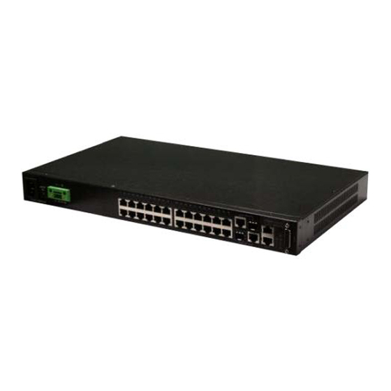
NTRODUCTION VERVIEW The ECS3810-26T is an intelligent Layer 2 switch designed for aggregating broadband traffic from the edge of a service provider’s (CO) network. It aggregates traffic using it's 24 Fast Ethernet ports, and two Gigabit Ethernet combination RJ-45/SFP ports, (see Figure 2 on page 24). -
Page 24: Figure 2: Front Panel
| Introduction HAPTER Overview Figure 2: Front Panel System Status Indicators Port Status Indicators AC Input DC Input Combination Alarm Port RJ-45/SFP Ports RJ-45 Management Power Switch RJ-45 Ports Port and Console Port Figure 3: Side Panel Ventilation WITCH RCHITECTURE This switch employs a wire-speed, non-blocking switching fabric. -
Page 25: Network Management Options
| Introduction HAPTER Network Management Options ETWORK ANAGEMENT PTIONS This switch contains a comprehensive array of LEDs for “at-a-glance” monitoring of network and port status. It also includes a management agent that allows you to configure or monitor the switch using its embedded management software, or through SNMP applications. -
Page 26: Description Of Hardware
| Introduction HAPTER Description of Hardware ESCRIPTION OF ARDWARE SFP S LOTS The two combination Small Form Factor Pluggable (SFP) transceiver slots are shared with two RJ-45 ports. In its default configuration, if an SFP transceiver (purchased separately) is installed in a slot and has a valid link on its port, the associated RJ-45 port is disabled and cannot be used. - Page 27 | Introduction HAPTER Description of Hardware Each port also supports auto-negotiation of flow control, so the switch can automatically prevent port buffers from becoming saturated. 10/100BASE-TX M ANAGEMENT The 10/100BASE-TX port provides a dedicated management interface that is segregated from the data traffic crossing the other ports. This port supports auto-negotiation, so the optimum transmission mode (half or full duplex) and data rate (10, or 100 Mbps) can be selected automatically, if this feature is also supported by the attached device.
-
Page 28: Table 1: System Status Leds
| Introduction HAPTER Description of Hardware ORT AND YSTEM TATUS This switch includes a display panel for key system and port indications that simplifies installation and network troubleshooting. The LEDs, which are located on the front panel for easy viewing, are shown below and described in the following tables. -
Page 29: Table 2: 100 Mbps Port Status Leds (1~24)
| Introduction HAPTER Description of Hardware Table 2: 100 Mbps Port Status LEDs (1~24) Condition Status (1~12) On/Flashing Green Port has established a valid 100 Mbps network connection. Flashing indicates activity. On/Flashing Amber Port has established a valid 10 Mbps network connection. - Page 30 | Introduction HAPTER Description of Hardware – 30 –...
-
Page 31: Installing The Switch
NSTALLING THE WITCH ELECTING A Switch units can be mounted in a standard 19-inch equipment rack or on a flat surface. Be sure to follow the guidelines below when choosing a location. The site should: ◆ be at the center of all the devices you want to link and near a power ■... -
Page 32: Ethernet Cabling
| Installing the Switch HAPTER Ethernet Cabling THERNET ABLING To ensure proper operation when installing the switch into a network, make sure that the current cables are suitable for 10BASE-T, 100BASE-TX or 1000BASE-T operation. Check the following criteria against the current installation of your network: Cable type: Unshielded twisted pair (UTP) or shielded twisted pair (STP) ◆... -
Page 33: Equipment Checklist
After unpacking this switch, check the contents to be sure you have received all the components. Then, before beginning the installation, be sure you have all other necessary installation equipment. ACKAGE ONTENTS Fast Ethernet Switch (ECS3810-26T) ◆ Four adhesive foot pads ◆ Power cord—either US, Continental Europe or UK ◆... -
Page 34: Mounting
| Installing the Switch HAPTER Mounting OUNTING The switch can be mounted on a desktop, shelf, or rack mounted. Mounting instructions follow. ESKTOP OR HELF OUNTING Attach the four adhesive feet to the bottom of the first switch. Figure 7: Attaching the Adhesive Feet Set the device on a flat surface near an AC power source, making sure there are at least two inches of space on all sides for proper air flow. -
Page 35: Figure 8: Attaching The Brackets
| Installing the Switch HAPTER Mounting OUNTING Before rack mounting the switch, pay particular attention to the following factors: Temperature: Since the temperature within a rack assembly may be higher ◆ than the ambient room temperature, check that the rack-environment temperature is within the specified operating temperature range. -
Page 36: Figure 9: Installing The Switch In A Rack
| Installing the Switch HAPTER Mounting Mount the device in the rack, using four rack-mounting screws (not provided). Figure 9: Installing the Switch in a Rack – 36 –... -
Page 37: Installing An Optional Sfp Transceiver
| Installing the Switch HAPTER Installing an Optional SFP Transceiver SFP T NSTALLING AN PTIONAL RANSCEIVER Figure 10: Installing an Optional SFP Transceiver This switch supports 1000BASE-LX5, 1000BASE-LX15, 1000BASE-LHX, 1000BASE-ZX, and 100BASE-FX SFP-compatible transceivers. To install an SFP transceiver, do the following: Consider network and cabling requirements to select an appropriate SFP transceiver type. -
Page 38: Connecting To A Power Source
| Installing the Switch HAPTER Connecting to a Power Source ONNECTING TO A OWER OURCE This switch supports both AC and DC power supplies. The switch is grounded through its AC power cord. When AUTION connecting DC power, always connect the AC power cord. DC P ONNECTING OWER... -
Page 39: Figure 11: Dc Plug Connections
| Installing the Switch HAPTER Connecting to a Power Source Use a wire stripper to carefully strip about a half an inch of the outer insulation off the end of each wire, exposing the copper core. Twist the copper wire strands together to form a tight braid. If possible, solder the exposed braid of wire together for better conductivity. -
Page 40: Figure 12: Ac Power Socket
| Installing the Switch HAPTER Connecting to a Power Source Check the the PWR LED indicator as the switch is powered on. If not, recheck the power supply and power cable connections at the supply source and at power conversion module. AC P ONNECTING OWER... -
Page 41: Connecting To The Console Port
| Installing the Switch HAPTER Connecting to the Console Port Check that the PWR LED indicator on the switch is on. If not, recheck the power supply and power cable connections at the supply source and at power module. ONNECTING TO THE ONSOLE This port is used to connect a console device to the switch through a serial cable. -
Page 42: Connecting To The Alarm Port
| Installing the Switch HAPTER Connecting to the Alarm Port The serial port’s configuration requirements are as follows: Default Baud rate—115,200 bps ◆ Character Size—8 Characters ◆ Parity—None ◆ Stop bit—One ◆ Data bits—8 ◆ Flow control—none ◆ ONNECTING TO THE LARM The DB-15 alarm port on the switch’s front panel is used to provide 4 external customer site alarm inputs. -
Page 43: Table 5: System Status Leds
| Installing the Switch HAPTER Connecting to the Alarm Port Table 5: System Status LEDs Switch’s Alarm Port Function 3 (ALARM_IN3_EXT_P*) External alarm input 3 (external relay dry contact closure to pin 13). 4 (ALARM_IN4_EXT_P) External alarm input 4 (external relay dry contact closure to pin 8). - Page 44 | Installing the Switch HAPTER Connecting to the Alarm Port – 44 –...
-
Page 45: Making Network Connections
AKING ETWORK ONNECTIONS ONNECTING ETWORK EVICES This switch is designed to connect broadband access network devices to aggregation network devices in the service provider CO. It can connect to twisted-pair devices through its RJ-45 ports, or to fiber-optic devices through SFP transceivers. -
Page 46: Fiber Optic Sfp Devices
| Making Network Connections HAPTER Fiber Optic SFP Devices Attach the other end to an available port on the switch. Make sure each twisted pair cable does not exceed 100 meters (328 ft) in length. As each connection is made, the relevant Port LED (on the switch) corresponding to each port will light green or amber to indicate that the connection is valid. -
Page 47: Figure 16: Making Connections To Sfp Transceivers
| Making Network Connections HAPTER Fiber Optic SFP Devices light transmitted through the cable and lead to degraded performance on the port. Connect one end of the cable to the LC port on the switch and the other end to the LC port on the other device. Since LC connectors are keyed, the cable can be attached in only one orientation. -
Page 48: Connectivity Rules
| Making Network Connections HAPTER Connectivity Rules ONNECTIVITY ULES When adding hubs (repeaters) to your network, please follow the connectivity rules listed in the manuals for these products. However, note that because switches break up the path for connected devices into separate collision domains, you should not include the switch or connected cabling in your calculations for cascade length involving other devices. -
Page 49: Table 8: Maximum 1000Base-Lhx Gigabit Ethernet Cable Length
| Making Network Connections HAPTER Connectivity Rules Table 8: Maximum 1000BASE-LHX Gigabit Ethernet Cable Length Fiber Size Fiber Bandwidth Maximum Cable Length Connector 9/125 micron single- 40 km (24.9 miles) mode fiber Table 9: Maximum 1000BASE-ZX Gigabit Ethernet Cable Length Fiber Size Fiber Bandwidth Maximum Cable Length... -
Page 50: Table 13: Maximum Ethernet Cable Length
| Making Network Connections HAPTER Connectivity Rules 10 M THERNET OLLISION OMAIN Table 13: Maximum Ethernet Cable Length Type Cable Type Max. Cable Length Connector 10BASE-T Category 3 or better 100-ohm UTP 100 m (328 ft) RJ-45 PPLICATION OTES Full-duplex operation only applies to point-to-point access (such as when a switch is attached to a workstation, server or another switch). -
Page 51: Cable Labeling And Connection Records
| Making Network Connections HAPTER Cable Labeling and Connection Records ABLE ABELING AND ONNECTION ECORDS When planning a network installation, it is essential to label the opposing ends of cables and to record where each cable is connected. Doing so will enable you to easily locate inter-connected devices, isolate faults and change your topology without need for unnecessary time consumption. - Page 52 | Making Network Connections HAPTER Cable Labeling and Connection Records – 52 –...
-
Page 53: Table 14: Troubleshooting Chart
ROUBLESHOOTING IAGNOSING WITCH NDICATORS Table 14: Troubleshooting Chart Symptom Action PWR LED is Off ◆ Check connections between the switch, the power cord and the wall outlet. ◆ Contact your dealer for assistance. Port LED is Off ◆ Verify that the switch and attached device are powered on. ◆... -
Page 54: Troubleshooting
| Troubleshooting PPENDIX Power and Cooling Problems Table 14: Troubleshooting Chart (Continued) Symptom Action Major LED is Red ◆ One or more major system alarm(s) affecting traffic have occurred. ◆ Check the alarm filter mask to determine potential cause(s) of alarm. Minor LED is Amber ◆... -
Page 55: In-Band Access
| Troubleshooting PPENDIX In-Band Access CCESS You can access the management agent in the switch from anywhere within the attached network using Telnet, a Web browser, or other network management software tools. However, you must first configure the switch with a valid IP address, subnet mask, and default gateway. - Page 56 | Troubleshooting PPENDIX In-Band Access – 56 –...
-
Page 57: Cables
ABLES WISTED ABLE AND SSIGNMENTS For 10/100BASE-TX connections, the twisted-pair cable must have two pairs of wires. For 1000BASE-T connections the twisted-pair cable must have four pairs of wires. Each wire pair is identified by two different colors. For example, one wire might be green and the other, green with white stripes. -
Page 58: Table 15: 10/100Base-Tx Mdi And Mdi-X Port Pinouts
| Cables PPENDIX Twisted-Pair Cable and Pin Assignments 10BASE-T/100BASE-TX P SSIGNMENTS Use unshielded twisted-pair (UTP) or shielded twisted-pair (STP) cable for RJ-45 connections: 100-ohm Category 3 or better cable for 10 Mbps connections, or 100-ohm Category 5 or better cable for 100 Mbps connections. Also be sure that the length of any twisted-pair connection does not exceed 100 meters (328 feet). -
Page 59: Figure 18: Straight-Through Wiring
| Cables PPENDIX Twisted-Pair Cable and Pin Assignments Figure 18: Straight-through Wiring EIA/TIA 568B RJ-45 Wiring Standard 10/100BASE-TX Straight-through Cable White/Orange Stripe Orange White/Green Stripe End A End B Blue White/Blue Stripe Green White/Brown Stripe Brown ROSSOVER IRING If the twisted-pair cable is to join two ports and either both ports are labeled with an “X”... -
Page 60: Table 16: 1000Base-T Mdi And Mdi-X Port Pinouts
| Cables PPENDIX Twisted-Pair Cable and Pin Assignments 1000BASE-T P SSIGNMENTS All 1000BASE-T ports support automatic MDI/MDI-X operation, so you can use straight-through cables for all network connections to PCs or servers, or to other switches or hubs. The table below shows the 1000BASE-T MDI and MDI-X port pinouts. These ports require that all four pairs of wires be connected. -
Page 61: Table 17: 1000Base-T Mdi And Mdi-X Port Pinouts
| Cables PPENDIX Twisted-Pair Cable and Pin Assignments 1000BASE-T DJUSTING XISTING ATEGORY ABLING TO If your existing Category 5 installation does not meet one of the test parameters for 1000BASE-T, there are basically three measures that can be applied to try and correct the problem: Replace any Category 5 patch cables with high-performance Category 5e or Category 6 cables. - Page 62 | Cables PPENDIX Twisted-Pair Cable and Pin Assignments Table 17: 1000BASE-T MDI and MDI-X Port Pinouts (Continued) ITU-T Description Application Standard G.654 1550-nm Loss-Minimized Extended long-haul applications. FiberSingle-mode, 9/125- Optimized for high-power micron core transmission in the 1500 to 1600-nm region, with low loss in the 1550-nm band.
-
Page 63: Specifications
PECIFICATIONS HYSICAL HARACTERISTICS ORTS 24 RJ-45 ports, 10/100 Mbps, with auto-negotiation, 2 combination RJ-45/SFP ports, 10/100/1000 Mbps, with auto-negotiation, 1 100BASE-TX management port ETWORK NTERFACE Ports 1-24: RJ-45 connector, auto MDI/X 10BASE-T: RJ-45 (100-ohm, UTP cable; Category 3 or better) 100BASE-TX: RJ-45 (100-ohm, UTP cable;... - Page 64 | Specifications PPENDIX Physical Characteristics System: PWR, DIAG, MGMT, ALM/MJR, ALM/MIN Port: Status (link, speed, and activity) EIGHT 3.2 kg (7.05 lbs) (W x D x H): 252 mm x 440 mm x 44 mm (9.92 x 17.32 x 1.73 inches) EMPERATURE Operating: 0°C to 60°C (32°F to 140°F) Storage: -40°C to 70°C (-40°F to 158°F)
-
Page 65: Switch Features
| Specifications PPENDIX Switch Features AXIMUM URRENT 0.31 A @ 100 VAC 0.15 A @ 240 VAC WITCH EATURES ORWARDING Store-and-forward HROUGHPUT Wire speed ONTROL Full Duplex: IEEE 802.3x Half Duplex: Back pressure ANAGEMENT EATURES ANAGEMENT Web, Telnet, SSH, or SNMP manager ANAGEMENT RS-232 RJ-45 console port OFTWARE... -
Page 66: Standards
| Specifications PPENDIX Standards TANDARDS IEEE 802.3-2005 Ethernet, Fast Ethernet, Gigabit Ethernet Full-duplex flow control IEEE 802.1D Spanning Tree Protocol IEEE 802.1w Rapid Spanning Tree Protocol IEEE 802.1s Multiple Spanning Tree Protocol IEEE 802.1Q Virtual LAN ISO/IEC 8802-3 CSMA/CD OMPLIANCES MISSIONS EN 55022:2007, Class A/B EN 61000-3-2:2006, Class A... -
Page 67: Glossary
LOSSARY 10BASE-T IEEE 802.3 specification for 10 Mbps Ethernet over two pairs of Category 3, 4, or 5 UTP cable. 100BASE-FX Medium-haul Gigabit Ethernet over two strands of 9/125 micron, or 62.5/125 or 50/125 multimode fiber core fiber cable. 100BASE-TX IEEE 802.3u specification for 100 Mbps Ethernet over two pairs of Category 5 UTP cable. - Page 68 LOSSARY 1000BASE-T IEEE 802.3ab specification for Gigabit Ethernet over 100-ohm Category 5, 5e or 6 twisted-pair cable (using all four wire pairs). EGOTIATION Signalling method allowing each node to select its optimum operational mode (e.g., speed and duplex mode) based on the capabilities of the node to which it is connected.
- Page 69 LOSSARY UPLEX Transmission method that allows two network devices to transmit and receive concurrently, effectively doubling the bandwidth of that link. IGABIT THERNET A 1000 Mbps network communication system based on Ethernet and the CSMA/ CD access method. IEEE Institute of Electrical and Electronic Engineers. IEEE 802.3 Defines carrier sense multiple access with collision detection (CSMA/CD) access method and physical layer specifications.
- Page 70 LOSSARY Light emitting diode used for monitoring a device or network condition. (LAN) OCAL ETWORK A group of interconnected computer and support devices. (MAC) EDIA CCESS ONTROL A portion of the networking protocol that governs access to the transmission medium, facilitating the exchange of data between network nodes. An acronym for Management Information Base.
- Page 71 LOSSARY (TCP/IP) RANSMISSION ONTROL ROTOCOL NTERNET ROTOCOL Protocol suite that includes TCP as the primary transport protocol, and IP as the network layer protocol. (UDP) ATAGRAM ROTOCOL provides a datagram mode for packet-switched communications. It uses IP as the underlying transport mechanism to provide access to IP-like services. UDP packets are delivered just like IP packets –...
- Page 72 LOSSARY – 72 –...
-
Page 73: Index
NDEX UMERICS 10 Gbps connectivity rules electrical interference, avoiding 10 Mbps connectivity rules equipment checklist 100 Mbps connectivity rules Ethernet connectivity rules 1000 Mbps connectivity rules 1000BASE-LH fiber cable Lengths 1000BASE-LX fiber cable Lengths 1000BASE-SX fiber cable Lengths Fast Ethernet connectivity rules 1000BASE-T front panel of switch pin assignments... - Page 74 NDEX pin assignments 1000BASE-T 10BASE-T/100BASE-TX ports, connecting to power, connecting to rack mounting rear panel of switch RJ-45 port connections pinouts rubber foot pads, attaching serial cable wiring map SFP transceiver slots site selelction specifications compliances environmental power standards compliance IEEE status LEDs surge suppressor, using...
- Page 76 ECS3810-26T E092011-CS-R01 150200000309A...
Need help?
Do you have a question about the ECS3810-26T and is the answer not in the manual?
Questions and answers