Table of Contents
Advertisement
Quick Links
Wireless Video Intercom
IVP-GU(G)
(Gateway Chime Unit)
Installation Instructions
1.
IMPORTANT NOTICE
Operations under harsh environments such as out of warranted temperature,
rapid temperature change, high humidity, constant moisturization may cause the
unit to malfunction.
Electronic device such as TVs, Radios, PCs, Microwave ovens or any other device
with an electric motor may cause the unit to malfunction.
Impact or shocks can cause severe damage to the unit. Please handle the unit
with care and operate without exerting strong forces.
Transmission range of communication between units may decrease under
the following conditions.
- Any unit is installed on a metal surface.
- Presence of reinforced concrete, steel doors or other metal construction
materials between units.
- Places near strong radio sources such as broadcast stations or substations.
While installing/using a Gateway Chime Unit
- Do not install/use in damp, steamy or dusty environments.
- Do not hold the Gateway Chime Unit to your ear - your hearing could be damaged.
- Do not install in an unstable location or where subject to strong vibration.
3.
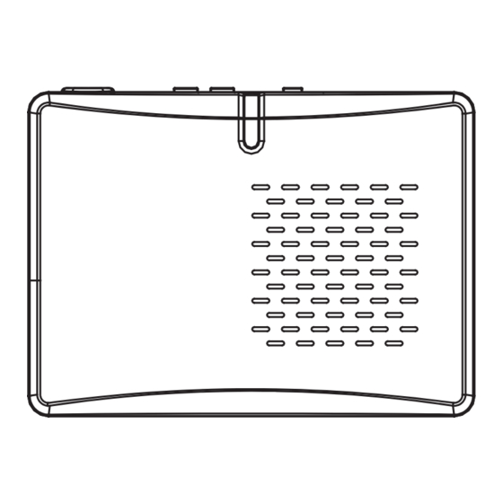
PARTS IDENTIFICATION
LED Indicator
Relay output
Speaker
Power input
Gateway Chime Unit (Front)
5.
INSTALLATION
One iVISION+ system can host up to 2 units of Gateway Chime Unit (IVP-GU).
If "OPEN DOOR" Relay Output function is used, please carefully choose a location for each of IVP-GU to secure a physical access to the IVP-GU.
For the optimal radio performance, mount IVP-GUs high on a wall and in an open area avoiding a metal surface and surrounding.
21mm / 0.83
Mounting Screw
Mounting Plate
(1) Fix a Mounting Plate on a feasible location
Pairing button A& B
Chime ON/OFF switch
Mounting Screw
Mounting Plate
Fixing Screw
Gateway Chime Unit (Back)
to Relay output
to a third party
(optional)
equipment
to Power input
to a power source
(2) Run a power cable to the location
and connect to the Power input.
If applicable, also run a relay connection
from the Relay output to the third
party equipment.
ATTENTION:
Thank you for purchasing the iVISION+ wireless video intercom.
Before installation and usage, please read this instruction manual thoroughly
and keep this safe for future reference.
IVP-GU(G) features
"OPEN DOOR" Relay Output Function
AC/DC (10~24V) Adaptable
Chime On-Off Mode
* Relay Output function must meet other requirements dependent on the third party equipment.
OPTEX will not be held responsible for any damage or injuries caused due to using this function.
2.
CHOOSING LOCATION
If there is a pre-existing door bell inside the house, a Gateway Chime Unit (IVP-GU)
may be capable of adapting the pre-existing power wires (AC/DC 10-24V 3 Wmax).
IVP-GU should be located in a place where the unit has a clear signal reception
and transmission availability.
The performance of a IVP-GU is dependent on the transmission environment of radio
signals from locations of connecting units. A communication range will be significantly
reduced by more number and thickness of walls which the signal is required to pass.
For iVISION+ system, maximum communication range is around 300ft (100m)
in an open air environment. Following materials may decrease the maximum
communication range and may potentially cause loss of transmission signals.
• Metal barricades such as metal doors and shutters.
• Walls with aluminium foil insulation.
• Concrete or galvanized metal walls.
Gateway Chime Unit uses 2.4GHz radio frequency for iVISION+ system.
4.
POWERING THE UNIT
The Gateway Chime Unit needs to be powered from an AC/DC 10-24V 3W(max)
power source. An open ended third party power adapter may be available from
local electronics stores. Power input has no polarity. Please make sure to tighten
terminal screws to avoid loose ends.
If applicable, configure all pairing setup and carry out feasibility study before
mounting on a wall.
N.C.
COM
N.O.
Relay output
Power input
AC/DC
10-24V
Slide on
Tighten a screw
(3) Slide the IVP-GU onto
the Mounting Plate and
tighten the Fixing Screw
at the bottom.
Advertisement
Table of Contents

Related Manuals for Optex iVISION+ IVP-GU


Summary of Contents for Optex iVISION+ IVP-GU
-
Page 1: Installation Instructions
Chime On-Off Mode (Gateway Chime Unit) * Relay Output function must meet other requirements dependent on the third party equipment. OPTEX will not be held responsible for any damage or injuries caused due to using this function. Installation Instructions IMPORTANT NOTICE... - Page 2 To completely turn off the chime, set Sound ON/OFF Switch to OFF. SPECIFICATION Dimensions Specification Table MODEL NAME: OPTEX iVISION+ (IVP-GU) Gateway Chime Unit Operating Temperature 0 to 40 degC (32 to 104 degF) Operating Humidity < 90% RH (no condensation)
Need help?
Do you have a question about the iVISION+ IVP-GU and is the answer not in the manual?
Questions and answers