Advertisement
Quick Links
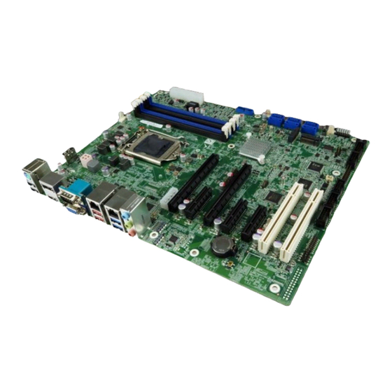
ATX motherboard supports 14nm LGA1151 Intel® Xeon® E, 8th/9th
Gen Intel® Core™ i9/i7/i5/i3, Celeron® and Pentium® processor,
DDR4, triple independent display, dual GbE LAN, M.2, USB 3.2,
Quick Installation Guide
Package List
IMBA-C2460 package includes the following items:
1 x IMBA-C2460 single board computer
1 x I/O shielding
2 x SATA cable
1 x QIG
SATA 6Gb/s, HD Audio and RoHS
IMBA-C2460
Version 1.0
November 2, 2020
©2020 Copyright by IEI Integration Corp.
All rights reserved.
Advertisement

Related Manuals for IEI Technology IMBA-C2460


Summary of Contents for IEI Technology IMBA-C2460
- Page 1 SATA 6Gb/s, HD Audio and RoHS IMBA-C2460 Quick Installation Guide Version 1.0 November 2, 2020 Package List IMBA-C2460 package includes the following items: 1 x IMBA-C2460 single board computer 1 x I/O shielding 2 x SATA cable ...
-
Page 2: Specifications
Specifications CPU: LGA1151 socket supports Intel® Xeon® E, 8th/9th Gen Intel® Core™ i9/i7/i5/i3, Pentium® or Celeron® processor System Chipset: Intel® C246 Memory: Four 288-pin 2666/2400 MHz dual-channel DDR4 SDRAM unbuffered DIMMs supported up to 64GB BIOS: AMI UEFI BIOS ... - Page 3 2 x USB 3.2 Gen 1 (2x10 pin, p=2.0) 3 x RS-232 (2x5 pin, p=2.54) 2 x RS-232/422/485 (2x5 pin, p=2.54) 1 x KB/MS (1x6 pin, p=2.0) SMBus: 1 x SMBus (1x4 pin) I²C: 1 x I²C (1x4 pin) ...
- Page 4 IEI Resource Download Center IMBA-C2460 are available on IEI https://download.ieiworld.com Resource Download Center. Type IMBA-C2460 and press Enter to find all the relevant software, utilities, and documentation. To install software from the downloaded ISO file, mount the file as a virtual drive to view its content.
-
Page 5: Ordering Information
Ordering Information IMBA-C2460-R10: ATX motherboard supports 14nm LGA1151 Intel® Xeon® E, 8th/9th Gen. Intel® Core™ i9/i7/i5/i3, Celeron® and Pentium® processor, DDR4, triple independent displays, dual GbE LAN, M.2, USB 3.2, SATA 6Gb/s, HD Audio and RoHS 19800-000075-RS: PS/2 KB/MS cable with bracket, 220mm, P=2.0 ... -
Page 6: Jumpers Setting And Connectors
Jumpers setting and connectors LABEL FUNCTION J_CMOS1 Clear CMOS SW_BIOS1_2 Switch BIOS1 or BIOS2 (optional function) J_ATX_AT1 AT/ATX Power Mode Setting USB SW1 Power USB Power Setting (via BIOS) USB SW2 Power J_FLASH1 Flash Descriptor Security Override F_PANEL1 PWR & RST Buttons and Indicators KB_MS1 Internal Keyboard &... - Page 7 CHASSIS1 Chassis Intrustion Connector AUDIO_CV1 External HD Audio Connector External VGA Connector and Serial Port VGACOM1 Connector HDMI_DP1 HDMI Connector and DisplayPort++ Connector LAN1_USB1 RJ-45 LAN and USB 3.2 Gen 2 Connector LAN2_USB2 RJ-45 LAN and USB 3.2 Gen 1 Connector K/M_USB1 Keyboard &...
- Page 8 USB SW1 Power, USB SW2 Power: USB Power Setting USB SW1 DESCRIPTION +5V DUAL 5V DUAL (Default) Aptio Setup Utility – Copyright (C) 2012 American Megatrends, Inc. Chipset Auto Power Button Status [Disabled(ATX)] Restore AC Power Loss [Last State] ------------------ >...
- Page 9 USB1, USB2: Internal USB 2.0 Connectors PIN NO. DESCRIPTION PIN NO. DESCRIPTION USB_DATA- USB_DATA+ USB_DATA+ USB_DATA- USB3 ‐1 : Internal USB 3.2 Gen 1 Connector PIN NO. DESCRIPTION PIN NO. DESCRIPTION USB_DATA+ USB3_RX ‐ USB_DATA ‐ USB3_RX+ USB3_TX+ USB3_TX ‐ USB3_TX ‐...
- Page 10 M2_A1: M.2 A-Key Connector PIN NO. DESCRIPTION PIN NO. DESCRIPTION +3.3V USB2_DP +3.3V USB2_DN PETP0 PETN0 PERP0 PERN0 PCIE_CLK+ PCIE_CLK- PLT_RST PCIE_WAKE W_DIS...
- Page 11 CLK_REQ +3.3V +3.3V +3.3V COM2, COM3, COM4: Internal RS-232 Serial Port Connectors PIN NO. DESCRIPTION PIN NO. DESCRIPTION COM5, COM6: Internal RS-232/422/485 Serial Port Connectors PIN NO. DESCRIPTION PIN NO. DESCRIPTION...
- Page 12 FRONT-PANEL1 : Front Panel Audio Connector PIN NO. DESCRIPTION PIN NO. DESCRIPTION MIC2 AUD_GND ‐L MIC2 PRESENCE# ‐R LINE2 MIC2 ‐R ‐JD FRONT ‐IO LINE2 LINE2 ‐L ‐JD SATA1, SATA2, SATA3, SATA4, SATA5, SATA6: SATA 6Gb/s Connectors PIN NO. DESCRIPTION PIN NO.
- Page 13 PETP0 PETN0 PERP0 PERN0 PCIE_CLK+ PCIE_CLK- PLT_RST PCIE_WAKE W_DIS CLK_REQ +3.3V +3.3V +3.3V CPU_FAN1: CPU Fan Connector PIN NO. DESCRIPTION PIN NO. DESCRIPTION +12V FANIO SYS_FAN1: System Fan Connector PIN NO. DESCRIPTION PIN NO. DESCRIPTION FANIO...
- Page 14 SYS_FAN2: System Fan Connector PIN NO. DESCRIPTION PIN NO. DESCRIPTION +12V DIO1 : Digital Input/Output Connector PIN NO. DESCRIPTION PIN NO. DESCRIPTION Output 3 Output 2 Output 1 Output 0 Input 3 Input 2 Input 1 Input 0 ATX1: 24-pin ATX Power Source Connector PIN NO.
- Page 15 ATXPWR1: PCIe Power Connector PIN NO. DESCRIPTION PIN NO. DESCRIPTION +12V TPM1: Trusted Platform Module Connector PIN NO. DESCRIPTION PIN NO. DESCRIPTION LCLK LFRAME# LRERST# LAD3 LAD2 +3.3V LAD1 LAD0 SB3V SERIRQ GLKRUN# LPCPD# LDRQ# CN1: EC Debug Connector PIN NO. DESCRIPTION PIN NO.
- Page 16 JSPI1: Flash SPI ROM Connector PIN NO. DESCRIPTION PIN NO. DESCRIPTION +3.3V SPI_CS SPI_CLK SPI_SO SPI_SI JSPI2: Flash EC ROM Connector PIN NO. DESCRIPTION PIN NO. DESCRIPTION +3.3V SPI_CS SPI_CLK SPI_SO SPI_SI SMB1: SMBus Connector PIN NO. DESCRIPTION PIN NO. DESCRIPTION SMB_DATA SMB_CLK...
- Page 17 CHASSIS1: Chassis Intrusion Connector DESCRIPTION DESCRIPTION +3.3VSB CHASSIS OPEN AUDIO_CV1 : Audio Line-In/Out MIC Connector PIN NO. DESCRIPTION Line-in CD/DVD or other audio source input port (Blue) Line-out Connect this port to headphone or speaker (Green) Microphone Connect this port to microphone (Pink) VGACOM1: External VGA Connector and Serial Port Connector 15-pin VGA Female Connector...
- Page 18 HDMI_DP1: HDMI Connector and DisplayPort Connector HDMI Connector PIN NO. DESCRIPTION PIN NO. DESCRIPTION HDMI_DATA2 HDMI_DATA2# HDMI_SCL HDMI_DATA1 HDMI_SDA HDMI_DATA1# HDMI_DATA0 HDMI_HPD HDMI_GND HDMI_DATA0# HDMI_GND HDMI_CLK HDMI_GND HDMI_GND HDMI_CLK# DisplayPort++ Connector PIN NO. DESCRIPTION PIN NO. DESCRIPTION HDMI_DATA2 HDMI_DATA2# HDMI_SCL HDMI_DATA1 HDMI_SDA HDMI_DATA1#...
- Page 19 LAN1_USB1: Ethernet and USB 3.2 Gen 2 Connectors External USB 3.2 Gen 2 Connectors PIN NO. DESCRIPTION PIN NO. DESCRIPTION USB_DATA- USB_DATA- USB_DATA+ USB_ DATA+ USB3_RX- USB3_RX- USB3_RX+ USB3_ RX+ USB3_TX- USB3_TX- USB3_TX+ USB3_TX+ RJ-45 LAN Connector (LAN1) PIN NO. DESCRIPTION PIN NO.
- Page 20 LAN2_USB2: Ethernet and USB 3.2 Gen 1 Connectors External USB 3.2 Gen 1 Connectors PIN NO. DESCRIPTION PIN NO. DESCRIPTION USB_DATA- USB_DATA- USB_DATA+ USB_ DATA+ USB3_RX- USB3_RX- USB3_RX+ USB3_ RX+ USB3_TX- USB3_TX- USB3_TX+ USB3_TX+ RJ-45 LAN Connector (LAN2) PIN NO. DESCRIPTION PIN NO.
- Page 21 Board Layout: Jumper and Connector Locations (Unit: mm)
Need help?
Do you have a question about the IMBA-C2460 and is the answer not in the manual?
Questions and answers