Table of Contents
Advertisement
Quick Links
IMBA-C2060 ATX Motherboard
MODEL:
IMBA-C2060
ATX LGA1155 Motherboard for Intel® Core™ i3 Quad/Dual Core
CPU, Intel® C206 Chipset, DDR3, VGA/DVI/HDMI,
Dual Intel® PCIe GbE, Intel® AMT 7.0 Support, Two USB 3.0
Ports, Five COM Ports, Two SATA 6Gb/s Ports and RoHS
User Manual
Page i
Rev. 2.01 – 23 April, 2014
Advertisement
Table of Contents

Related Manuals for IEI Technology IMBA-C2060


Summary of Contents for IEI Technology IMBA-C2060
-
Page 1: User Manual
IMBA-C2060 ATX Motherboard MODEL: IMBA-C2060 ATX LGA1155 Motherboard for Intel® Core™ i3 Quad/Dual Core CPU, Intel® C206 Chipset, DDR3, VGA/DVI/HDMI, Dual Intel® PCIe GbE, Intel® AMT 7.0 Support, Two USB 3.0 Ports, Five COM Ports, Two SATA 6Gb/s Ports and RoHS... - Page 2 IMBA-C2060 ATX Motherboard Revision Date Version Changes 2.01 Modified Table 3-24: LAN Pinouts 23 April, 2014 2.00 Updated for R20 version 9 December, 2013 1.03 Added Appendix F: Intel® Matrix Storage Manager 9 November, 2012 1.02 Modified Section4.3.1: AT/ATX Power Select Jumper 9 September, 2011 ®...
- Page 3 IMBA-C2060 ATX Motherboard Copyright COPYRIGHT NOTICE The information in this document is subject to change without prior notice in order to improve reliability, design and function and does not represent a commitment on the part of the manufacturer. In no event will the manufacturer be liable for direct, indirect, special, incidental, or consequential damages arising out of the use or inability to use the product or documentation, even if advised of the possibility of such damages.
-
Page 4: Table Of Contents
PTIONAL TEMS 3 CONNECTORS ......................14 3.1 P ..............15 ERIPHERAL NTERFACE ONNECTORS 3.1.1 IMBA-C2060 Layout..................15 3.1.2 Peripheral Interface Connectors ..............16 3.1.3 External Interface Panel Connectors............... 17 3.2 I ..............18 NTERNAL ERIPHERAL ONNECTORS 3.2.1 ATX Power Connector ..................18 3.2.2 Battery Connectors .................. - Page 5 IMBA-C2060 ATX Motherboard 3.2.11 Keyboard/Mouse Connector................28 3.2.12 Parallel Port Connector ................29 3.2.13 PCI Slots ......................30 3.2.14 PCIe x4 Slots....................31 3.2.15 PCIe x8 Slot ....................32 3.2.16 PCI Express x16/x8 Slot................. 32 3.2.17 SATA 3Gb/s Drive Connector ................ 33 3.2.18 SATA 6Gb/s Drive Connector ................
- Page 6 IMBA-C2060 ATX Motherboard 4.5 E ........... 63 XTERNAL ERIPHERAL NTERFACE ONNECTION 4.5.1 Audio Connector ....................63 4.5.2 DVI Display Device Connection..............64 4.5.3 HDMI Connection.................... 65 4.5.4 LAN Connection....................66 4.5.5 PS/2 Keyboard and Mouse Connection ............66 4.5.6 Serial Device Connection ................67 4.5.7 USB Connection (Dual Connector) ..............
- Page 7 IMBA-C2060 ATX Motherboard 5.4.1 North Bridge Configuration................102 5.4.2 South Bridge Configuration................104 5.4.3 Integrated Graphics ..................108 5.4.4 ME Subsystem ....................110 5.5 B ........................111 5.6 S ........................113 ECURITY 5.7 E ........................114 6 SOFTWARE DRIVERS .....................116 6.1 A ................117 VAILABLE...
- Page 8 IMBA-C2060 ATX Motherboard B.4.3 Restore Your Last Backup................171 B.4.4 Manual......................172 B.5 O .................... 173 THER NFORMATION B.5.1 Using AHCI Mode or ALi M5283 / VIA VT6421A Controller....... 173 B.5.2 System Memory Requirement ................ 175 C TERMINOLOGY ..................... 176 D DIGITAL I/O INTERFACE..................
- Page 9 IMBA-C2060 ATX Motherboard List of Figures Figure 1-1: IMBA-C2060 .........................2 Figure 1-2: Connectors ........................4 Figure 1-3: IMBA-C2060 Dimensions (mm)..................5 Figure 1-4: Data Flow Diagram......................6 Figure 3-1: Connectors and Jumpers..................15 Figure 3-2: ATX Power Connector Pinout Location..............18 Figure 3-3: Battery Connector Locations...................20 Figure 3-4: CPU Power Connector Location................21...
- Page 10 IMBA-C2060 ATX Motherboard Figure 3-27: External Peripheral Interface Connector ..............43 Figure 3-28: Audio Connector .....................44 Figure 3-29: Ethernet Connector....................44 Figure 3-30: Serial Port Connector Pinouts................47 Figure 3-31: VGA Connector .......................48 Figure 4-1: Disengage the CPU Socket Load Lever..............52 Figure 4-2: Remove Protective Cover..................53 Figure 4-3: Insert the Socket LGA1155 CPU................54...
- Page 11 IMBA-C2060 ATX Motherboard Figure 6-11: Graphics Driver Setup Operations ..............124 Figure 6-12: Graphics Driver Installation Finish Screen ............124 Figure 6-13: Intel® Network Connection Menu............... 125 Figure 6-14: LAN Driver Welcome Screen ................126 Figure 6-15: LAN Driver License Agreement ................126 Figure 6-16: LAN Driver Setup Options...................
- Page 12 IMBA-C2060 ATX Motherboard Figure B-8: Build-up Recovery Partition ................. 158 Figure B-9: Press any key to continue ..................158 Figure B-10: Press F3 to Boot into Recovery Mode............... 159 Figure B-11: Recovery Tool Menu ................... 159 Figure B-12: About Symantec Ghost Window ................ 160 Figure B-13: Symantec Ghost Path ..................
- Page 13 IMBA-C2060 ATX Motherboard List of Tables Table 1-1: IMBA-C2060 Specifications ..................8 Table 2-1: Packing List.........................12 Table 2-2: Optional Items......................13 Table 3-1: Peripheral Interface Connectors ................17 Table 3-2: Rear Panel Connectors ....................17 Table 3-3: ATX Power Connector Pinouts .................19 Table 3-4: Battery Connector (BT2) Pinouts................20 Table 3-5: CPU Power Connector Pinouts .................21...
- Page 14 IMBA-C2060 ATX Motherboard Table 3-28: PS/2 Connector Pinouts...................46 Table 3-29: Serial Port Connector Pinouts ................47 Table 3-30: VGA Connector Pinouts...................47 Table 3-31: DVI Connector Pinouts.....................48 Table 4-1: Jumpers ........................58 Table 4-2: AT/ATX Power Mode Jumper Settings ..............59 Table 4-3: Clear BIOS Jumper Settings..................59 Table 4-4: Wake-on LAN Connector Pinouts ................60...
- Page 15 IMBA-C2060 ATX Motherboard BIOS Menus BIOS Menu 1: Main ........................75 BIOS Menu 2: Advanced ......................77 BIOS Menu 3: ACPI Configuration ....................77 BIOS Menu 4: TPM Configuration ....................78 BIOS Menu 5: CPU Configuration ....................79 BIOS Menu 6: CPU Configuration ....................80 BIOS Menu 7: SATA Configuration .....................82 BIOS Menu 8: Intel TXT(LT) Configuration ................84...
-
Page 17: Introduction
IMBA-C2060 ATX Motherboard Chapter Introduction Page 1... -
Page 18: Introduction
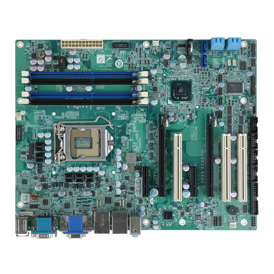
1.1 Introduction Figure 1-1: IMBA-C2060 The IMBA-C2060 is an ATX motherboard. It accepts a Socket LGA1155 Intel® Xeon® or Core™ i3 processor with quad or dual core and supports four 240-pin 1333/1066 MHz dual-channel DDR3 DIMM modules up to 32.0 GB maximum. The IMBA-C2060 includes a VGA, HDMI, and DVI-D port. -
Page 19: Features
IMBA-C2060 ATX Motherboard 1.3 Features Some of the IMBA-C2060 motherboard features are listed below: ATX form factor RoHS compliant LGA1155 CPU socket Three PCI card expansion slots Multiple PCIe expansion card configurations: Slot PCIe x16 PCIe x8 PCIe x4 Configuration 1... -
Page 20: Connectors
IMBA-C2060 ATX Motherboard 1.4 Connectors The connectors on the IMBA-C2060 are shown in the figure below. Figure 1-2: Connectors Page 4... -
Page 21: Dimensions
IMBA-C2060 ATX Motherboard 1.5 Dimensions The main dimensions of the IMBA-C2060 are shown in the diagram below. Figure 1-3: IMBA-C2060 Dimensions (mm) Page 5... -
Page 22: Data Flow
IMBA-C2060 ATX Motherboard 1.6 Data Flow F igure 1-4 shows the data flow between the system chipset, the CPU and other components installed on the motherboard. Figure 1-4: Data Flow Diagram Page 6... -
Page 23: Technical Specifications
IMBA-C2060 ATX Motherboard 1.7 Technical Specifications IMBA-C2060 technical specifications are listed below. Specification/Model IMBA-C2060 Form Factor LGA1155 Intel® Xeon® or Core™ i3 processor with quad/dual core CPU Supported Intel® C206 Chipset Integrated Graphics Supports DirectX 10.1/OpenGL 3.0 Full MPEG2, VC1, AVC Decode... -
Page 24: Table 1-1: Imba-C2060 Specifications
(3.40 GHz Intel® Xeon® E3-1275 CPU with four 1333 MHz 2GB DDR3 memory) -10ºC–60ºC Operating Temperature -20ºC–70ºC Storage Temperature 5%–95% (non-condensing) Operating Humidity Physical Specifications 244 mm x 305 mm Dimensions 1200 g / 700 g Weight GW/NW Table 1-1: IMBA-C2060 Specifications Page 8... -
Page 25: Packing List
IMBA-C2060 ATX Motherboard Chapter Packing List Page 9... -
Page 26: Anti-Static Precautions
Only handle the edges of the PCB: Don't touch the surface of the motherboard. Hold the motherboard by the edges when handling. 2.2 Unpacking Precautions When the IMBA-C2060 is unpacked, please do the following: Follow the antistatic guidelines above. Make sure the packing box is facing upwards when opening. -
Page 27: Packing List
If any of the components listed in the checklist below are missing, do not proceed with the installation. Contact the IEI reseller or vendor the IMBA-C2060 was purchased from or contact an IEI sales representative directly by sending an email to ales@ieiworld.com.tw. -
Page 28: Optional Items
IMBA-C2060 ATX Motherboard Quantity Item and Part Number Image Quick Installation Guide Table 2-1: Packing List 2.4 Optional Items The following are optional components which may be separately purchased: Item and Part Number Image Dual ports USB cable with bracket... -
Page 29: Table 2-2: Optional Items
IMBA-C2060 ATX Motherboard Item and Part Number Image LGA1155/LGA1156 cooler kit (95W) (P/N: CF-1156E-R11) 20-pin Infineon TPM module, S/W management tool, firmware v3.17 (P/N: TPM-IN01-R11) Table 2-2: Optional Items Page 13... -
Page 30: Connectors
IMBA-C2060 ATX Motherboard Chapter Connectors Page 14... -
Page 31: Peripheral Interface Connectors
IMBA-C2060 ATX Motherboard 3.1 Peripheral Interface Connectors This chapter details all the jumpers and connectors. 3.1.1 IMBA-C2060 Layout The figures below show all the connectors and jumpers. Figure 3-1: Connectors and Jumpers Page 15... -
Page 32: Peripheral Interface Connectors
IMBA-C2060 ATX Motherboard 3.1.2 Peripheral Interface Connectors The table below lists all the connectors on the board. Connector Type Label ATX Power connector 24-pin ATX ATX1 Battery connector 2-pin wafer Battery holder CR2032 battery holder BAT1 CPU power connector 4-pin Molex... -
Page 33: External Interface Panel Connectors
IMBA-C2060 ATX Motherboard Connector Type Label Serial port, RS-422/485 4-pin wafer COM4 Serial port, RS-232 10-pin box header COM1, COM2, COM3, COM5 SMBus connector 4-pin wafer SMBUS_1 SPDIF connector 5-pin header SPDIF1 SPI ROM connector 8-pin header JSPI1 TPM connector... -
Page 34: Internal Peripheral Connectors
IMBA-C2060 ATX Motherboard 3.2 Internal Peripheral Connectors The section describes all of the connectors on the IMBA-C2060. 3.2.1 ATX Power Connector CN Label: ATX1 24-pin ATX CN Type: CN Location: See Figure 3-2 CN Pinouts: See Table 3-3 The ATX power connector connects to an ATX power supply. -
Page 35: Battery Connectors
IMBA-C2060 ATX Motherboard Description Description +12V +12V +3.3V Table 3-3: ATX Power Connector Pinouts 3.2.2 Battery Connectors CAUTION: Risk of explosion if battery is replaced by an incorrect type. Only certified engineers should replace the on-board battery. Dispose of used batteries according to instructions and local regulations. -
Page 36: Cpu Power Connector
IMBA-C2060 ATX Motherboard Figure 3-3: Battery Connector Locations Description Battery+ Table 3-4: Battery Connector (BT2) Pinouts 3.2.3 CPU Power Connector CN Label: CPU12V1 CN Type: 4-pin Molex CN Location: See Figure 3-4 CN Pinouts: See Table 3-5 The CPU power input connector provides power to the CPU. -
Page 37: Ddr3 Dimm Slots
IMBA-C2060 ATX Motherboard Figure 3-4: CPU Power Connector Location PIN NO. DESCRIPTION +12V +12V Table 3-5: CPU Power Connector Pinouts 3.2.4 DDR3 DIMM Slots CN Label: CHA_DIMM1, CHA_DIMM2, CHB_DIMM1, CHB_DIMM2 DDR3 DIMM slot CN Type: CN Location: F igure 3-5 The DIMM slots are for DDR3 DIMM memory modules. -
Page 38: Digital I/O Connector
IMBA-C2060 ATX Motherboard Figure 3-5: DDR3 DIMM Slot Locations 3.2.5 Digital I/O Connector CN Label: DIO1 CN Type: 10-pin header CN Location: See Figure 3-6 CN Pinouts: See Table 3-6 The digital I/O connector provides programmable input and output for external devices. -
Page 39: Fan Connector (Cpu)
IMBA-C2060 ATX Motherboard Figure 3-6: Digital I/O Connector Location PIN NO. DESCRIPTION PIN NO. DESCRIPTION Output 3 Output 2 Output 1 Output 0 Input 3 Input 2 Input 1 Input 0 Table 3-6: Digital I/O Connector Pinouts 3.2.6 Fan Connector (CPU) -
Page 40: Fan Connector (System)
IMBA-C2060 ATX Motherboard Figure 3-7: CPU Fan Connector Location PIN NO. DESCRIPTION +12 V FANIO1 Table 3-7: CPU Fan Connector Pinouts 3.2.7 Fan Connector (System) CN Label: SYS_FAN1, SYS_FAN2 CN Type: 3-pin wafer CN Location: See Figure 3-8 CN Pinouts: See Table 3-8 The fan connector attaches to a cooling fan. -
Page 41: Front Panel Audio Connector
IMBA-C2060 ATX Motherboard Figure 3-8: System Fan Connector Location PIN NO. DESCRIPTION FANIO +12 V (PWM) Table 3-8: System Fan Connector Pinouts 3.2.8 Front Panel Audio Connector CN Label: FP_AUDIO1 10-pin header CN Type: CN Location: See Figure 3-9 CN Pinouts: See Table 3-9 This connector connects to speakers, a microphone and an audio input. -
Page 42: Front Panel Connector
IMBA-C2060 ATX Motherboard Figure 3-9: Front Panel Audio Connector Location Description Description LMIC2_L AUD GND LMIC2_R PRESENCE# LLINE2-R MIC2-JD F_SENSE LLINE2-L LINE2-JD Table 3-9: Front Panel Audio Connector Pinouts 3.2.9 Front Panel Connector CN Label: F_PANEL1 CN Type: 14-pin header... -
Page 43: I2C Connector
IMBA-C2060 ATX Motherboard Figure 3-10: Front Panel Connector Location FUNCTION DESCRIPTION FUNCTION DESCRIPTION Power LED ACPILED Speaker Beep Power Power Button PWRBT_SW#_C PC Beep Reset HDD LED HDDLED EXTRST- HDDLED- Table 3-10: Front Panel Connector Pinouts 3.2.10 I2C Connector CN Label:... -
Page 44: Keyboard/Mouse Connector
IMBA-C2060 ATX Motherboard Figure 3-11: I2C Connector Location Description +5V_DUAL PCH_GP38_PU PCH_GP39_PU Table 3-11: I2C Connector Pinouts 3.2.11 Keyboard/Mouse Connector CN Label: KB_MS1 6-pin wafer CN Type: See Figure 3-12 CN Location: CN Pinouts: See Table 3-12 The keyboard/mouse connector connects to a PS/2 Y-cable that can be connected to a PS/2 keyboard and mouse. -
Page 45: Parallel Port Connector
IMBA-C2060 ATX Motherboard Figure 3-12: Keyboard/Mouse Connector Location Description +5 V KB DATA MS DATA MS CLK KB DATA KB CLK GROUND Table 3-12: Keyboard/Mouse Connector Pinouts 3.2.12 Parallel Port Connector CN Label: LPT1 CN Type: 26-pin box header CN Location:... -
Page 46: Pci Slots
IMBA-C2060 ATX Motherboard Figure 3-13: Parallel Port Connector Location Description Description RSTROBE# RPD0 RPD1 RPD2 RPD3 RPD4 RPD5 RPD6 RPD7 SIO_ACK# SIO_BUSY SIO_PE SIO_SLCT SIO_AFD# SIO_ERR# SIO_INIT# SIO_SLIN# Table 3-13: Parallel Port Connector Pinouts 3.2.13 PCI Slots CN Label: PCI1, PCI2, PCI3... -
Page 47: Pcie X4 Slots
IMBA-C2060 ATX Motherboard The PCI slot enables a PCI expansion module to be connected to the board. Figure 3-14: PCI Slot Locations 3.2.14 PCIe x4 Slots CN Label: PCIEX4_1, PCIEX4_2 CN Type: PCIe x4 slot CN Location: See Figure 3-18 The PCIe x4 slot is for PCIe x4 expansion cards. -
Page 48: Pcie X8 Slot
IMBA-C2060 ATX Motherboard 3.2.15 PCIe x8 Slot CN Label: PCIEX8_1 PCIe x16 slot CN Type: CN Location: See Figure 3-18 The PCIe x8 slot provide PCIe x8 signal for PCIe expansion cards. Figure 3-16: PCIe x8 Slot Location 3.2.16 PCI Express x16/x8 Slot... -
Page 49: Sata 3Gb/S Drive Connector
IMBA-C2060 ATX Motherboard Figure 3-17: PCIe x16 Slot Location 3.2.17 SATA 3Gb/s Drive Connector CN Label: SATA34, SATA56 CN Type: 14-pin SATA connector CN Location: See Figure 3-18 See Table 3-14 CN Pinouts: The SATA drive connectors can be connected to SATA drives and support up to 3Gb/s data transfer rate. -
Page 50: Sata 6Gb/S Drive Connector
IMBA-C2060 ATX Motherboard Figure 3-18: SATA 3Gb/s Drive Connector Location Description Description SATATXP_A SATATXP_B SATATXN_A SATATXN_B SATARXN_A SATARXN_B SATARXP_A SATARXP_B Table 3-14: SATA 3Gb/s Drive Connector Pinouts 3.2.18 SATA 6Gb/s Drive Connector CN Label: SATA1, SATA2 CN Type: 7-pin SATA drive connectors... -
Page 51: Serial Port Connector, Rs-422/485
IMBA-C2060 ATX Motherboard Figure 3-19: SATA 6Gb/s Drive Connector Location Description SATATXP SATATXN SATARXN SATARXP Table 3-15: SATA 6Gb/s Drive Connector Pinouts 3.2.19 Serial Port Connector, RS-422/485 CN Label: COM4 CN Type: 4-pin wafer CN Location: See Figure 3-20 CN Pinouts:... -
Page 52: Figure 3-20: Rs-422/485 Connector Location
IMBA-C2060 ATX Motherboard This connector provides RS-422 or RS-485 communications. Figure 3-20: RS-422/485 Connector Location PIN NO. DESCRIPTION RXD422- RXD422+ TXD422+/TXD485+ TXD422-/TXD485- Table 3-16: RS-422/485Connector Pinouts Use the optional RS-422/485 cable to connect to a serial device. The pinouts of the D-sub 9 connector are listed below. -
Page 53: Serial Port Connectors, Rs-232
IMBA-C2060 ATX Motherboard 3.2.20 Serial Port Connectors, RS-232 CN Label: COM1, COM2, COM3, COM5 10-pin box header CN Type: CN Location: See Figure 3-21 CN Pinouts: See Table 3-18 Each of these connectors provides RS-232 connections. Figure 3-21: Serial Port Connector Location PIN NO. -
Page 54: Spdif Connector
IMBA-C2060 ATX Motherboard CN Pinouts: See Table 3-19 The SMBus (System Management Bus) connector provides low-speed system management communications. Figure 3-22: SMBus Connector Location Description +5V_DUAL SMBCLK SMBDATA Table 3-19: SMBus Connector Pinouts 3.2.22 SPDIF Connector CN Label: SPDIF1 CN Type:... -
Page 55: Spi Rom Connector
IMBA-C2060 ATX Motherboard Figure 3-23: SPDIF Connector Location DESCRIPTION SPDIFOUT SPDIFIN Table 3-20: SPDIF Connector Pinouts 3.2.23 SPI ROM Connector CN Label: JSPI1 CN Type: 8-pin header CN Location: See Figure 3-8 CN Pinouts: See Table 3-8 The SPI connector is used to flash the BIOS. -
Page 56: Tpm Connector
IMBA-C2060 ATX Motherboard Figure 3-24: SPI Connector Location PIN NO. DESCRIPTION PIN NO. DESCRIPTION +3.3V SPI_CS0 SPI_CLK SPI_SO0 SPI_SI Table 3-21: SPI Connector Pinouts 3.2.24 TPM Connector CN Label: TPM1 CN Type: 20-pin header CN Location: See Figure 3-8 CN Pinouts: See Table 3-8 The TPM connector connects to a TPM module. -
Page 57: Usb Connectors
IMBA-C2060 ATX Motherboard Figure 3-25: TPM Connector Location PIN NO. DESCRIPTION PIN NO. DESCRIPTION LCLK GND2 LERAME# LRESRT# LAD3 LAD2 LAD1 LAD0 GND3 SB3V SERIRQ GND1 GLKRUN# LPCPD# LDRQ# Table 3-22: TPM Connector Pinouts 3.2.25 USB Connectors CN Label: USB1, USB2, USB3, USB4... -
Page 58: Figure 3-26: Usb Connector Pinout Locations
IMBA-C2060 ATX Motherboard Figure 3-26: USB Connector Pinout Locations PIN NO. DESCRIPTION PIN NO. DESCRIPTION DATA- DATA+ DATA+ DATA- Table 3-23: USB Port Connector Pinouts Page 42... -
Page 59: External Peripheral Interface Connector Panel
IMBA-C2060 ATX Motherboard 3.3 External Peripheral Interface Connector Panel The figure below shows the external peripheral interface connector (EPIC) panel. The EPIC panel consists of the following: Figure 3-27: External Peripheral Interface Connector 3.3.1 Audio Connector CN Label: AUDIO_CV1 CN Type:... -
Page 60: Ethernet And Usb Connector
IMBA-C2060 ATX Motherboard Figure 3-28: Audio Connector 3.3.2 Ethernet and USB Connector CN Label: LAN1_USB01, LAN2_USB23 CN Type: RJ-45, USB 2.0 and USB 3.0 connectors CN Location: See Figure 3-27 See Table 3-24 CN Pinouts: The LAN connector connects to a local network. -
Page 61: Hdmi Port Connector
IMBA-C2060 ATX Motherboard Description Description on: linked off: 10 Mb/s blinking: data is being sent/received green: 100 Mb/s orange: 1000 Mb/s Table 3-25: Connector LEDs The USB connector can be connected to a USB device. The USB 2.0 ports are labeled as USB01 and the USB 3.0 ports are labels as USB23. -
Page 62: Keyboard/Mouse Connector
IMBA-C2060 ATX Motherboard PIN NO. DESCRIPTION PIN NO. DESCRIPTION HDMI_DATA0# HDMI_GND HDMI_CLK HDMI_GND HDMI_GND HDMI_CLK# Table 3-27: HDMI Connector Pinouts 3.3.4 Keyboard/Mouse Connector CN Label: KB_MS2 Dual PS/2 CN Type: CN Location: See Figure 3-27 CN Pinouts: See Table 3-28 The PS/2 ports are for connecting a PS/2 mouse and a PS/2 keyboard. -
Page 63: Vga And Dvi Connector
IMBA-C2060 ATX Motherboard PIN NO. DESCRIPTION PIN NO. DESCRIPTION NDCD NDSR NRXD NRTS NTXD NCTS NDTR Table 3-29: Serial Port Connector Pinouts Figure 3-30: Serial Port Connector Pinouts 3.3.6 VGA and DVI Connector CN Label: VIDEO1 15-pin Female, 24-pin header... -
Page 64: Figure 3-31: Vga Connector
IMBA-C2060 ATX Motherboard Figure 3-31: VGA Connector The DVI connector connects to a monitor that supports DVI video input. DESCRIPTION DESCRIPTION DVI_TMDS_C_DATA2# DVI_TMDS_C_DATA2 DVI_DDC_SCLK DVI_DDC_SDATA DVI_TMDS_C_DATA1# DVI_TMDS_C_DATA1 +5V_DVI DVI_HPD DVI_TMDS_C_DATA0# DVI_TMDS_C_DATA0 DVI_TMDS_C_CLK DVI_TMDS_C_CLK# Table 3-31: DVI Connector Pinouts Page 48... -
Page 65: Installation
IMBA-C2060 ATX Motherboard Chapter Installation Page 49... -
Page 66: Anti-Static Precautions
Electrostatic discharge (ESD) can cause serious damage to electronic components, including the IMBA-C2060. Dry climates are especially susceptible to ESD. It is therefore critical that whenever the IMBA-C2060 or any other electrical component is handled, the following anti-static precautions are strictly adhered to. - Page 67 This helps to prevent potential ESD damage. Turn all power to the IMBA-C2060 off: When working with the IMBA-C2060, make sure that it is disconnected from all power supplies and that no electricity is being fed into the system.
-
Page 68: Socket Lga1155 Cpu Installation
IMBA-C2060 ATX Motherboard 4.2.1 Socket LGA1155 CPU Installation WARNING: CPUs are expensive and sensitive components. When installing the CPU please be careful not to damage it in anyway. Make sure the CPU is installed properly and ensure the correct cooling kit is properly installed. -
Page 69: Figure 4-2: Remove Protective Cover
IMBA-C2060 ATX Motherboard Figure 4-2: Remove Protective Cover Step 3: Inspect the CPU socket. Make sure there are no bent pins and make sure the socket contacts are free of foreign material. If any debris is found, remove it with compressed air. -
Page 70: Figure 4-3: Insert The Socket Lga1155 Cpu
IMBA-C2060 ATX Motherboard Figure 4-3: Insert the Socket LGA1155 CPU Step 8: Close the CPU socket. Close the load plate and pull the load lever back a little to have the load plate be able to secure to the knob. Engage the load lever by pushing it back to its original position (Figure 4-4). -
Page 71: Socket Lga1155 Cooling Kit Installation
IMBA-C2060 ATX Motherboard 4.2.2 Socket LGA1155 Cooling Kit Installation WARNING: DO NOT attempt to install a push-pin cooling fan. The pre-installed support bracket prevents the board from bending and is ONLY compatible with captive screw type cooling fans. Figure 4-5: Cooling Kits (CF-1156A-RS and CF-1156E-RS) The cooling kit can be bought from IEI. -
Page 72: Figure 4-6: Cooling Kit Support Bracket
Secure the cooling kit by fastening the four retention screws of the cooling kit. Step 5: Connect the fan cable. Connect the cooling kit fan cable to the fan connector on the IMBA-C2060. Carefully route the cable and avoid heat generating chips and fan blades.Step 0:... -
Page 73: Dimm Installation
IMBA-C2060 ATX Motherboard 4.2.3 DIMM Installation To install a DIMM, please follow the steps below and refer to Figure 4-7. Figure 4-7: DIMM Installation Step 1: Open the DIMM socket handles. Open the two handles outwards as far as they can. See Figure 4-7. -
Page 74: Jumper Settings
IMBA-C2060 ATX Motherboard 4.3 Jumper Settings NOTE: A jumper is a metal bridge used to close an electrical circuit. It consists of two or three metal pins and a small metal clip (often protected by a plastic cover) that slides over the pins to connect them. To... -
Page 75: Clear Cmos Jumper
IMBA-C2060 ATX Motherboard Setting Description Closed ATX power (Default) Open AT power Table 4-2: AT/ATX Power Mode Jumper Settings Figure 4-8: AT/ATX Power Mode Jumper Location 4.3.2 Clear CMOS Jumper Jumper Label: J_CMOS1 3-pin header Jumper Type: Jumper Settings: See Table 4-3... -
Page 76: Wake-On Lan Jumper
IMBA-C2060 ATX Motherboard Figure 4-9: Clear BIOS Jumper Location 4.3.3 Wake-on LAN Jumper CN Label: WOL_SEL1 3-pin header CN Type: CN Location: See Figure 4-10 CN Pinouts: See Table 4-4 The Wake-on LAN connector allows the user to enable or disable the Wake-on LAN (WOL) function. -
Page 77: Internal Peripheral Device Connections
This section outlines the installation of peripheral devices to the onboard connectors. 4.4.1 SATA Drive Connection The IMBA-C2060 is shipped with four SATA drive cables. To connect the SATA drives to the connectors, please follow the steps below. Step 1: Locate the connectors. -
Page 78: Figure 4-11: Sata Drive Cable Connection
IMBA-C2060 ATX Motherboard Figure 4-11: SATA Drive Cable Connection Step 3: Connect the cable to the SATA disk. Connect the connector on the other end of the cable to the connector at the back of the SATA drive. See Figure 4-12. -
Page 79: External Peripheral Interface Connection
This section describes connecting devices to the external connectors on the IMBA-C2060. 4.5.1 Audio Connector The audio jacks on the external audio connector enable the IMBA-C2060 to be connected to a stereo sound setup. Each jack supports both input and output. When connecting a device, the High Definition Audio utility will automatically detect input or output. -
Page 80: Dvi Display Device Connection
IMBA-C2060 ATX Motherboard 4.5.2 DVI Display Device Connection The IMBA-C2060 has a single female DVI-I connector on the external peripheral interface panel. The DVI-I connector is connected to a digital display device. To connect a digital display device to the IMBA-C2060, please follow the instructions below. -
Page 81: Hdmi Connection
IMBA-C2060 ATX Motherboard 4.5.3 HDMI Connection The HDMI connector transmits a digital signal to compatible HDMI display devices such as a TV or computer screen. To connect the HDMI cable to the IMBA-C2060, follow the steps below. Step 1: Locate the HDMI connector. The location is shown in a previous section. -
Page 82: Lan Connection
Step 0: 4.5.5 PS/2 Keyboard and Mouse Connection The IMBA-C2060 has a dual PS/2 connector on the external peripheral interface panel. The dual PS/2 connector is used to connect to a keyboard and mouse to the system. Follow the steps below to connect a keyboard and mouse to the IMBA-C2060. -
Page 83: Serial Device Connection
Figure 4-17: PS/2 Keyboard/Mouse Connector 4.5.6 Serial Device Connection The IMBA-C2060 has a single male D-sub 9 connector on the external peripheral interface panel for a serial device. Follow the steps below to connect a serial device to the IMBA-C2060. -
Page 84: Usb Connection (Dual Connector)
IMBA-C2060 ATX Motherboard Figure 4-18: Serial Device Connector Step 3: Secure the connector. Secure the serial device connector to the external interface by tightening the two retention screws on either side of the connector. Step 0: 4.5.7 USB Connection (Dual Connector) The external USB Series "A"... -
Page 85: Vga Monitor Connection
Figure 4-19: USB Connector 4.5.8 VGA Monitor Connection The IMBA-C2060 has a single female D-sub 15 connector on the external peripheral interface panel. The D-sub 15 connector is connected to a CRT or VGA monitor. To connect a monitor to the IMBA-C2060, please follow the instructions below. -
Page 86: Intel ® Amt Setup Procedure
® 4.6 Intel AMT Setup Procedure The IMBA-C2060 is featured with the Intel® Active Management Technology (AMT). To enable the Intel® AMT function, follow the steps below. Step 1: Make sure the CHA_DIMM1 socket is installed with one DDR3 DIMM. - Page 87 IMBA-C2060 ATX Motherboard process. Enter the Intel® current ME password as it requires (the Intel® default password is admin). NOTE: To change the password, enter a new password following the strong password rule (containing at least one upper case letter, one lower case letter, one digit and one special character, and be at least eight characters).
-
Page 88: Bios
IMBA-C2060 ATX Motherboard Chapter BIOS Page 72... -
Page 89: Introduction
IMBA-C2060 ATX Motherboard 5.1 Introduction The BIOS is programmed onto the BIOS chip. The BIOS setup program allows changes to certain system settings. This chapter outlines the options that can be changed. NOTE: Some of the BIOS options may vary throughout the life cycle of the product and are subject to change without prior notice. -
Page 90: Getting Help
IMBA-C2060 ATX Motherboard Function Increase the numeric value or make changes Decrease the numeric value or make changes Page Up key Increase the numeric value or make changes Page Dn key Decrease the numeric value or make changes Esc key Main Menu –... -
Page 91: Main
IMBA-C2060 ATX Motherboard Security – Sets User and Supervisor Passwords. Save & Exit – Selects exit options and loads default settings The following sections completely describe the configuration options found in the menu items at the top of the BIOS screen and listed above. -
Page 92: Advanced
IMBA-C2060 ATX Motherboard Memory Information The Memory Information lists a brief summary of the on-board memory. The fields in Memory Information cannot be changed. Total Memory: Displays the auto-detected system memory size and type. The System Overview field also has two user configurable fields: System Date [xx/xx/xx] Use the System Date option to set the system date. -
Page 93: Acpi Settings
IMBA-C2060 ATX Motherboard Aptio Setup Utility – Copyright (C) 2011 American Megatrends, Inc. Main Advanced Chipset Boot Security Save & Exit > ACPI Settings System ACPI Parameters > Trusted Computing > CPU Configuration > SATA Configuration > Intel TXT(LT) Configuration ---------------------- >... -
Page 94: Trusted Computing
IMBA-C2060 ATX Motherboard ACPI Sleep State [S1 (CPU Stop Clock)] Use the ACPI Sleep State option to specify the sleep state the system enters when it is not being used. Suspend Disabled The system enters S1(POS) sleep state. The (CPU... -
Page 95: Cpu Configuration
IMBA-C2060 ATX Motherboard TPM Support [Disable] Use the TPM Support option to configure support for the TPM. TPM support is disabled. Disable EFAULT Enable TPM support is enabled. 5.3.3 CPU Configuration Use the CPU Configuration menu (BIOS Menu 5) to enter the CPU Information submenu or enable Intel Virtualization Technology. -
Page 96: Cpu Information
IMBA-C2060 ATX Motherboard Intel Virtualization Technology [Disabled] Use the Intel Virtualization Technology option to enable or disable virtualization on the system. When combined with third party software, Intel® Virtualization technology allows several OSs to run on the same system at the same time. - Page 97 IMBA-C2060 ATX Motherboard Processor Cores: Lists the number of the processor core Intel HT Technology: Indicates if Intel HT Technology is supported by the CPU. Intel VT-x Technology: Indicates if Intel VT-x Technology is supported by the CPU. Intel SMX Technology: Indicates if Intel SMX Technology is supported by the CPU.
-
Page 98: Sata Configuration
IMBA-C2060 ATX Motherboard 5.3.4 SATA Configuration Use the SATA Configuration menu (BIOS Menu 7) to change and/or set the configuration of the SATA devices installed in the system. Aptio Setup Utility – Copyright (C) 2011 American Megatrends, Inc. Advanced SATA Configuration (1) IDE Mode. -
Page 99: Intel Txt(Lt) Configuration
IMBA-C2060 ATX Motherboard Disable Disables SATA devices. Configures SATA devices as normal IDE device. IDE Mode AHCI Mode Configures SATA devices as AHCI device. EFAULT RAID Mode Configures SATA devices as RAID device. Staggered Spin-up [Disabled] Staggered Spin-up allows the system to power up one drive at a time to prevent excess power consumption. -
Page 100: Usb Configuration
IMBA-C2060 ATX Motherboard Aptio Setup Utility – Copyright (C) 2011 American Megatrends, Inc. Advanced Intel Trusted Execution Technology Configuration Intel TXT support only can be enabled/disabled if SMX is enabled. VT and VT-d support must also be enabled prior --------------------- to TXT. - Page 101 IMBA-C2060 ATX Motherboard USB Support [Enabled] Use the USB Support option to enable or disable USB support on the system. USB support disabled Disabled Enabled USB support enabled EFAULT Legacy USB Support [Enabled] Use the Legacy USB Support BIOS option to enable USB mouse and USB keyboard support.
-
Page 102: Super Io Configuration
IMBA-C2060 ATX Motherboard 5.3.7 Super IO Configuration Use the Super IO Configuration menu (BIOS Menu 10) to set or change the configurations for the FDD controllers, parallel ports and serial ports. Aptio Setup Utility – Copyright (C) 2011 American Megatrends, Inc. -
Page 103: Serial Port N Configuration
IMBA-C2060 ATX Motherboard 5.3.7.1 Serial Port n Configuration Use the Serial Port n Configuration menu (BIOS Menu 11) to configure the serial port n. Aptio Setup Utility – Copyright (C) 2011 American Megatrends, Inc. Advanced Serial Port n Configuration Enable or Disable Serial... - Page 104 IMBA-C2060 ATX Motherboard IO=3F8h; Serial Port I/O port address is 3F8h and the interrupt IRQ=3, 4 address is IRQ3, 4 Serial Port I/O port address is 2F8h and the interrupt IO=2F8h; address is IRQ3, 4 IRQ=3, 4 IO=2C0h; Serial Port I/O port address is 2C0h and the interrupt...
- Page 105 IMBA-C2060 ATX Motherboard IO=2C8h; Serial Port I/O port address is 2C8h and the interrupt IRQ=3, 4 address is IRQ3, 4 5.3.7.1.3 Serial Port 3 Configuration Serial Port [Enabled] Use the Serial Port option to enable or disable the serial port.
- Page 106 IMBA-C2060 ATX Motherboard 5.3.7.1.4 Serial Port 4 Configuration Serial Port [Enabled] Use the Serial Port option to enable or disable the serial port. Disabled Disable the serial port Enable the serial port Enabled EFAULT Change Settings [Auto] Use the Change Settings option to change the serial port IO port address and interrupt address.
- Page 107 IMBA-C2060 ATX Motherboard 5.3.7.1.5 Serial Port 5 Configuration Serial Port [Enabled] Use the Serial Port option to enable or disable the serial port. Disabled Disable the serial port Enable the serial port Enabled EFAULT Change Settings [Auto] Use the Change Settings option to change the serial port IO port address and interrupt address.
- Page 108 IMBA-C2060 ATX Motherboard Disabled Disable the serial port Enable the serial port Enabled EFAULT Change Settings [Auto] Use the Change Settings option to change the serial port IO port address and interrupt address. Auto The serial port IO port address and interrupt address EFAULT are automatically detected.
-
Page 109: Parallel Port Configuration
IMBA-C2060 ATX Motherboard 5.3.7.2 Parallel Port Configuration Use the Parallel Port Configuration menu (BIOS Menu 11) to configure the serial port n. Aptio Setup Utility – Copyright (C) 2010 American Megatrends, Inc. Advanced Parallel Port Configuration Change the Printer Port... -
Page 110: H/W Monitor
IMBA-C2060 ATX Motherboard IO=3BCh; Parallel Port I/O port address is 3BCh and the IRQ=7 interrupt address is IRQ7 Device Mode [Printer Mode] Use the Device Mode option to select the mode the parallel port operates in. Configuration options are listed below. -
Page 111: Fan 1 Configuration
IMBA-C2060 ATX Motherboard PC Health Status The following system parameters and values are shown. The system parameters that are monitored are: System Temperatures: CPU Temperature System Temperature Fan Speeds: CPU Fan Speed System Fan Speed Voltages: VCC3V Vcore +1.05V VDDR... -
Page 112: Bios Menu 14: Fan 1 Configuration
IMBA-C2060 ATX Motherboard Aptio Setup Utility – Copyright (C) 2011 American Megatrends, Inc. Advanced PC Health Status CPU Smart Fan control [Auto by RPM] Target Temp Sensor [CPU Temperature] Temperature Bound 1 Temperature Bound 2 Temperature Bound 3 Temperature Bound 4... -
Page 113: Fan 2 Configuration
IMBA-C2060 ATX Motherboard System Sets the target temperature sensor to the System Temperature1 Temperature1 setting. Sets the target temperature sensor to the System System Temperature2 setting. Temperature2 Temperature Bound n Use the + or – key to change the fan Temperature Bound n value. Enter a decimal number between 0 and 127. -
Page 114: Bios Menu 15: Fan 2 Configuration
IMBA-C2060 ATX Motherboard Aptio Setup Utility – Copyright (C) 2011 American Megatrends, Inc. Advanced PC Health Status CPU Smart Fan control [Auto by Duty-Cycle] Target Temp Sensor [CPU Temperature] Temperature Bound 1 Temperature Bound 2 Temperature Bound 3 Temperature Bound 4... -
Page 115: Serial Port Console Redirection
IMBA-C2060 ATX Motherboard System Sets the target temperature sensor to the System Temperature1 Temperature1 setting. Sets the target temperature sensor to the System System Temperature2 setting. Temperature2 Temperature Bound n Use the + or – key to change the fan Temperature Bound n value. Enter a decimal number between 0 and 127. -
Page 116: Bios Menu 16: Serial Port Console Redirection
IMBA-C2060 ATX Motherboard Aptio Setup Utility – Copyright (C) 2011 American Megatrends, Inc. Advanced COM1 Console Redirection Console Redirection [Disabled] Enable or Disable > Console Redirection Settings COM2 Console Redirection [Disabled] > Console Redirection Settings COM3 Console Redirection [Disabled] > Console Redirection Settings... -
Page 117: Chipset
IMBA-C2060 ATX Motherboard ANSI The target terminal type is ANSI Bits per second [115200] Use the Bits per second option to specify the serial port transmission speed. The speed must match the other side. Long or noisy lines may require lower speeds. -
Page 118: North Bridge Configuration
IMBA-C2060 ATX Motherboard Aptio Setup Utility – Copyright (C) 2011 American Megatrends, Inc. Main Advanced Chipset Boot Security Save & Exit > North Bridge North Bridge Parameters > South Bridge > Integrated Graphics > ME Subsystem --------------------- : Select Screen ↑... - Page 119 IMBA-C2060 ATX Motherboard Initiate Graphic Adapter [PEG/IGD] Use the Initiate Graphic Adapter option to select the graphics controller used as the primary boot device. Select either an integrated graphics controller (IGD) or a combination of PCI graphics controller, a PCI express (PEG) controller or an IGD. Configuration...
-
Page 120: South Bridge Configuration
IMBA-C2060 ATX Motherboard 288 M 288 MB of memory used by internal graphics device 320 MB of memory used by internal graphics 320 M device 352 M 352 MB of memory used by internal graphics device 384 M 384 MB of memory used by internal graphics... -
Page 121: Bios Menu 19: Southbridge Chipset Configuration
IMBA-C2060 ATX Motherboard Aptio Setup Utility – Copyright (C) 2011 American Megatrends, Inc. Chipset Auto Power Button Status [OFF] Enabled/Disabled GbE Controller. Before On-Chip GbE Configuration disabling GbE, AMT GbE Controller [Enabled] function must be GbE PXE Boot [Disabled] disabled. - Page 122 IMBA-C2060 ATX Motherboard Restore on AC Power Loss [Power Off] Use the Restore on AC Power Loss BIOS option to specify what state the system returns to if there is a sudden loss of power to the system. Power Off...
- Page 123 IMBA-C2060 ATX Motherboard Disabled Disables Resume on PS/2 option Enables Resume on PS/2 option Enabled EFAULT Azalia HD Audio [Enabled] Use the Azalia HD Audio option to enable or disable the High Definition Audio controller. Disabled The onboard High Definition Audio controller is disabled...
-
Page 124: Integrated Graphics
IMBA-C2060 ATX Motherboard PCIe LAN PXE Boot [Disabled] Use the PCIe LAN PXE Boot option to enable or disable the boot option for the PCIe LAN PXE. Disabled Disables PCIe LAN PXE Boot option EFAULT Enables PCIe LAN PXE Boot option Enabled PCIe USB3.0 Controller [Enabled]... -
Page 125: Bios Menu 20: Integrated Graphics
IMBA-C2060 ATX Motherboard Aptio Setup Utility – Copyright (C) 2011 American Megatrends, Inc. Advanced Intel IGD SWSCI OpRegion Configuration Select DVMT Mode used by Internal Graphics Device DVMT Mode Select [DVMT Mode] DVMT Memory [Maximum] --------------------- IGD - Boot Type... -
Page 126: Me Subsystem
IMBA-C2060 ATX Motherboard AUTO EFAULT HDMI 5.4.4 ME Subsystem Use the ME Subsystem menu (BIOS Menu 21) to configure the Intel® Management Engine (ME) configuration options. Aptio Setup Utility – Copyright (C) 2011 American Megatrends, Inc. Chipset Intel ME Subsystem Configuration... -
Page 127: Boot
IMBA-C2060 ATX Motherboard Unconfigure AMT/ME [Disabled] Use the Unconfigure AMT/ME option to perform AMT/ME unconfigure without password operation. Disabled Disable AMT/ME unconfigure EFAULT Enable AMT/ME unconfigure Enabled 5.5 Boot Use the Boot menu (BIOS Menu 22) to configure system boot options. - Page 128 IMBA-C2060 ATX Motherboard Does not enable the keyboard Number Lock automatically. To use the 10-keys on the keyboard, press the Number Lock key located on the upper left-hand corner of the 10-key pad. The Number Lock LED on the keyboard lights up when the Number Lock is engaged.
-
Page 129: Security
IMBA-C2060 ATX Motherboard 5.6 Security Use the Security menu (BIOS Menu 23) to set system and user passwords. Aptio Setup Utility – Copyright (C) 2011 American Megatrends, Inc. Main Advanced Chipset Boot Security Save & Exit Password Description Set Setup Administrator Password If ONLY the Administrator’s password is set,... -
Page 130: Exit
IMBA-C2060 ATX Motherboard 5.7 Exit Use the Exit menu (BIOS Menu 24) to load default BIOS values, optimal failsafe values and to save configuration changes. Aptio Setup Utility – Copyright (C) 2011 American Megatrends, Inc. Main Advanced Chipset Boot Security Save &... - Page 131 IMBA-C2060 ATX Motherboard Save as User Defaults Use the Save as User Defaults option to save the changes done so far as user defaults. Restore User Defaults Use the Restore User Defaults option to restore the user defaults to all the setup options.
-
Page 132: Software Drivers
IMBA-C2060 ATX Motherboard Chapter Software Drivers Page 116... -
Page 133: Available Software Drivers
Intel® IT Director application Installation instructions are given below. 6.2 Software Installation All the drivers for the IMBA-C2060 are on the CD that came with the system. To install the drivers, please follow the steps below. Step 1: Insert the CD into a CD drive connected to the system. -
Page 134: Figure 6-1: Introduction Screen
IMBA-C2060 ATX Motherboard Figure 6-1: Introduction Screen Step 3: Click IMBA-C2060. Step 4: A new screen with a list of available drivers appears (Figure 6-2). Figure 6-2: Available Drivers Step 5: Install all of the necessary drivers in this menu. -
Page 135: Chipset Driver Installation
IMBA-C2060 ATX Motherboard 6.3 Chipset Driver Installation To install the chipset driver, please do the following. Step 1: Access the driver list. (See Section 6.2) Step 2: Click “Chipset”. Step 3: Locate the setup file and double click on it. -
Page 136: Figure 6-4: Chipset Driver Welcome Screen
IMBA-C2060 ATX Motherboard Figure 6-4: Chipset Driver Welcome Screen Step 7: The license agreement in Figure 6-5 appears. Step 8: Read the License Agreement. Step 9: Click Yes to continue. Figure 6-5: Chipset Driver License Agreement Step 10: The Read Me file in Figure 6-6 appears. -
Page 137: Figure 6-6: Chipset Driver Read Me File
IMBA-C2060 ATX Motherboard Step 11: Click Next to continue. Figure 6-6: Chipset Driver Read Me File Step 12: Setup Operations are performed as shown in Figure 6-7. Step 13: Once the Setup Operations are complete, click Next to continue. Figure 6-7: Chipset Driver Setup Operations... -
Page 138: Graphics Driver Installation
IMBA-C2060 ATX Motherboard Step 14: The Finish screen in Figure 6-8 appears. Step 15: Select “Yes, I want to restart this computer now” and click Finish.Step 0: Figure 6-8: Chipset Driver Installation Finish Screen 6.4 Graphics Driver Installation To install the Graphics driver, please do the following. -
Page 139: Figure 6-9: Graphics Driver Welcome Screen
IMBA-C2060 ATX Motherboard Figure 6-9: Graphics Driver Welcome Screen Step 6: The License Agreement in Figure 6-10 appears. Step 7: Click Yes to accept the agreement and continue. Figure 6-10: Graphics Driver License Agreement Step 8: Setup Operations are performed as shown in Figure 6-11. -
Page 140: Figure 6-11: Graphics Driver Setup Operations
IMBA-C2060 ATX Motherboard Step 9: Once the Setup Operations are complete, click Next to continue. Figure 6-11: Graphics Driver Setup Operations Step 10: The Finish screen in Figure 6-12 appears. Step 11: Select “Yes, I want to restart this computer now” and click Finish.Step 0:... -
Page 141: Lan Driver Installation
IMBA-C2060 ATX Motherboard 6.5 LAN Driver Installation To install the LAN driver, please do the following. Step 1: Access the driver list. (See Section 6.2) Step 2: Click “LAN”. Step 3: Locate the Autorun file and double click it. Step 4: The Intel®... -
Page 142: Figure 6-14: Lan Driver Welcome Screen
IMBA-C2060 ATX Motherboard Figure 6-14: LAN Driver Welcome Screen Step 7: Click Next to continue. Step 8: The License Agreement in Figure 6-15 appears. Step 9: Accept the agreement by selecting “I accept the terms in the license agreement”. Step 10: Click Next to continue. -
Page 143: Figure 6-16: Lan Driver Setup Options
IMBA-C2060 ATX Motherboard Step 11: The Setup Options screen in Figure 6-16 appears. Step 12: Select program features to install. Step 13: Click Next to continue. Figure 6-16: LAN Driver Setup Options Step 14: The Ready to Install the Program screen in Figure 6-17 appears. -
Page 144: Figure 6-17: Lan Driver Installation
IMBA-C2060 ATX Motherboard Figure 6-17: LAN Driver Installation Step 16: The program begins to install. Step 17: When the driver installation is complete, the screen in Figure 6-18 appears. Step 18: Click Finish to exit. Figure 6-18: LAN Driver Installation Complete... -
Page 145: Audio Driver Installation
IMBA-C2060 ATX Motherboard 6.6 Audio Driver Installation To install the audio driver, please do the following. Step 1: Access the driver list. (See Section 6.2) Step 2: Click “Audio” and select the folder which corresponds to the operating system. Step 3: Double click the setup file. -
Page 146: Figure 6-20: Audio Driver Welcome Screen
IMBA-C2060 ATX Motherboard Figure 6-20: Audio Driver Welcome Screen Step 7: The audio driver installation begins. See Figure 6-21. Figure 6-21: Audio Driver Installation Step 8: When the installation is complete, the screen in Figure 6-22 appears. Step 9: Select “Yes, I want to restart my computer now” and click Finish. -
Page 147: Usb 3.0 Driver Installation
IMBA-C2060 ATX Motherboard 6.7 USB 3.0 Driver Installation To install the touch panel software driver, please follow the steps below. Step 1: Access the driver list. (See Section 6.2) Step 2: Click “USB 3.0”. Step 3: Locate the setup file and double click on it. -
Page 148: Figure 6-24: Usb 3.0 Driver License Agreement
IMBA-C2060 ATX Motherboard Figure 6-24: USB 3.0 Driver License Agreement Step 8: The Install screen appears and displays the progress of the installation F igure 6-25). Figure 6-25: USB 3.0 Driver Installation Screen Step 9: When the installation is complete, click F to exit setup. -
Page 149: Intel® Amt Driver And Application
IMBA-C2060 ATX Motherboard Figure 6-26: USB 3.0 Driver Update Complete 6.8 Intel® AMT Driver and Application 6.8.1 Intel® Management Engine Components Installation The package of the Intel® ME components includes Intel® Management Engine Interface (Intel® ME Interface) Serial Over LAN (SOL) driver... -
Page 150: Figure 6-27: Intel® Me Driver Welcome Screen
IMBA-C2060 ATX Motherboard Step 4: Locate the setup file and double click it. Step 5: When the setup files are completely extracted the Welcome Screen in Figure 6-27 appears. Step 6: Click Next to continue. Figure 6-27: Intel® ME Driver Welcome Screen Step 7: The license agreement in Figure 6-28 appears. -
Page 151: Figure 6-28: Intel® Me Driver License Agreement
IMBA-C2060 ATX Motherboard Figure 6-28: Intel® ME Driver License Agreement Step 10: The Read Me file in Figure 6-29 appears. Step 11: Click Next to continue. Figure 6-29: Intel® ME Driver Read Me File Page 135... -
Page 152: Figure 6-30: Intel® Me Driver Setup Operations
IMBA-C2060 ATX Motherboard Step 12: Setup Operations are performed as shown in Figure 6-30. Step 13: Once the Setup Operations are complete, click Next to continue. Figure 6-30: Intel® ME Driver Setup Operations Step 14: The Finish screen in Figure 6-31 appears. -
Page 153: Intel® It Director Application Installation
IMBA-C2060 ATX Motherboard Figure 6-31: Intel® ME Driver Installation Finish Screen 6.8.2 Intel® IT Director Application Installation Intel® IT Director is an application that helps address key IT security, data protection and network health concerns of small businesses. To install the Intel® IT Director application, please do the following. -
Page 154: Figure 6-32: It Director Welcome Screen
IMBA-C2060 ATX Motherboard Step 5: The Welcome Screen in Figure 6-32 appears. Step 6: Click Next to continue. Figure 6-32: IT Director Welcome Screen Step 7: The license agreement in Figure 6-33 appears. Step 8: Accept the agreement by selecting “I accept the terms in the license agreement”. -
Page 155: Figure 6-33: It Director License Agreement
IMBA-C2060 ATX Motherboard Figure 6-33: IT Director License Agreement Step 10: Continue to choose the installation type and the destination folder for the IT Director application. Step 11: The Ready to Install the Program screen in Figure 6-34 appears. Step 12: Click Install to proceed with the installation. -
Page 156: Figure 6-35: It Director Installation Complete
IMBA-C2060 ATX Motherboard Step 13: The program begins to install. Step 14: When the driver installation is complete, the screen in Figure 6-35 appears. Step 15: Click Next to configure the system for remote monitoring or Cancel to exit the program and configure the system later. -
Page 157: Figure 6-36: It Director Configuration Tool Welcome Screen
IMBA-C2060 ATX Motherboard Figure 6-36: IT Director Configuration Tool Welcome Screen NOTE: It is recommended to open the Intel® IT Director Getting Started Guide shown in Figure 6-36 to fully understand the configuration process. Step 17: Select whether this is the first computer you are creating a password for IT Director. -
Page 158: Figure 6-37: It Director - Creating Password
IMBA-C2060 ATX Motherboard Figure 6-37: IT Director – Creating Password Step 18: Follow the instructions to create a new password or enter the password created previously. Step 19: When the configuration is complete, the screen in Figure 6-38 appears. Step 20: Click Finish to exit. - Page 159 IMBA-C2060 ATX Motherboard Step 0: NOTE: If the network connection doesn’t work after installing the Intel® IT Director in a Windows Vista system, please install the network adapter driver. The driver is located at \7-iAMT, iTPM Driver & Utility\AMT Hot Fix\V1.0C0206 of the driver CD.
-
Page 160: Abios Options
IMBA-C2060 ATX Motherboard Appendix BIOS Options Page 144... - Page 161 IMBA-C2060 ATX Motherboard Below is a list of BIOS configuration options in the BIOS chapter. System Overview .........................75 Memory Information ......................76 System Date [xx/xx/xx] ......................76 System Time [xx:xx:xx] .......................76 ACPI Sleep State [S1 (CPU Stop Clock)] ................78 ...
- Page 162 IMBA-C2060 ATX Motherboard CPU Smart Fan control [Auto by RPM]................96 Target Temp. Sensor [CPU Temperature] .................96 Temperature Bound n......................97 Segment n Speed (%) ......................97 Full Speed Count .........................97 CPU Smart Fan control [Auto by Duty-Cycle]..............98 ...
- Page 163 IMBA-C2060 ATX Motherboard Bootup NumLock State [On].................... 111 Quiet Boot [Enabled] ......................112 Option ROM Messages [Keep Current] ................112 Administrator Password ....................113 User Password ........................113 Save Changes and Reset ....................114 ...
-
Page 164: B One Key Recovery
IMBA-C2060 ATX Motherboard Appendix One Key Recovery Page 148... -
Page 165: One Key Recovery Introduction
IMBA-C2060 ATX Motherboard B.1 One Key Recovery Introduction The IEI one key recovery is an easy-to-use front end for the Norton Ghost system backup and recovery tool. The one key recovery provides quick and easy shortcuts for creating a backup and reverting to that backup or for reverting to the factory default settings. -
Page 166: System Requirement
IMBA-C2060 ATX Motherboard B.1.1 System Requirement NOTE: The recovery CD can only be used with IEI products. The software will fail to run and a warning message will appear when used on non-IEI hardware. To create the system backup, the main storage device must be split into two partitions (three partitions for Linux). -
Page 167: Supported Operating System
IMBA-C2060 ATX Motherboard NOTE: Specialized tools are required to change the partition size if the operating system is already installed. B.1.2 Supported Operating System The recovery CD is compatible with both Microsoft Windows and Linux operating system (OS). The supported OS versions are listed below. -
Page 168: Setup Procedure For Windows
IMBA-C2060 ATX Motherboard NOTE: Installing unsupported OS versions may cause the recovery tool to fail. B.2 Setup Procedure for Windows Prior to using the recovery tool to backup or restore Windows system, a few setup procedures are required. Step 1: Hardware and BIOS setup (see Section B .2.1) -
Page 169: Create Partitions
IMBA-C2060 ATX Motherboard Step 4: Turn on the system. Step 5: Press the <DELETE> key as soon as the system is turned on to enter the BIOS. Step 6: Select the connected optical disk drive as the 1 boot device. (Boot... -
Page 170: Figure B-3: Recovery Tool Setup Menu
IMBA-C2060 ATX Motherboard Step 3: The recovery tool setup menu is shown as below. Figure B-3: Recovery Tool Setup Menu Step 4: Press <5> then <Enter>. Figure B-4: Command Mode Step 5: The command prompt window appears. Type the following commands (marked in red) to create two partitions. -
Page 171: Figure B-5: Partition Creation Commands
IMBA-C2060 ATX Motherboard system32>format F: /fs:ntfs /q /v:Recovery /y system32>exit Figure B-5: Partition Creation Commands Page 155... -
Page 172: Install Operating System, Drivers And Applications
IMBA-C2060 ATX Motherboard NOTE: Use the following commands to check if the partitions were created successfully. Step 6: Press any key to exit the recovery tool and automatically reboot the system. Please continue to the following procedure: Build-up Recovery Partition.S t e p 0 : B.2.3 Install Operating System, Drivers and Applications... -
Page 173: Build-Up Recovery Partition
IMBA-C2060 ATX Motherboard B.2.4 Build-up Recovery Partition Step 1: Put the recover CD in the optical drive. Step 2: Start the system. Step 3: Boot the system from recovery CD. When prompted, press any key to boot from the recovery CD. It will take a while to launch the recovery tool. Please be... -
Page 174: Figure B-8: Build-Up Recovery Partition
IMBA-C2060 ATX Motherboard recovery files in Section B .2.2 is hidden and the recovery tool is saved in this partition. Figure B-8: Build-up Recovery Partition Step 6: After completing the system configuration, press any key in the following window to reboot the system. -
Page 175: Create Factory Default Image
IMBA-C2060 ATX Motherboard B.2.5 Create Factory Default Image NOTE: Before creating the factory default image, please configure the system to a factory default environment, including driver and application installations. To create a factory default image, please follow the steps below. -
Page 176: Figure B-12: About Symantec Ghost Window
IMBA-C2060 ATX Motherboard Figure B-12: About Symantec Ghost Window Step 4: Use mouse to navigate to the option shown below ( F igure B-13). Figure B-13: Symantec Ghost Path Step 5: Select the local source drive (Drive 1) as shown in F igure B-14. -
Page 177: Figure B-14: Select A Local Source Drive
IMBA-C2060 ATX Motherboard Figure B-14: Select a Local Source Drive Step 6: Select a source partition (Part 1) from basic drive as shown in F igure B-15. Then click OK. Figure B-15: Select a Source Partition from Basic Drive Step 7: Select 1.2: [Recovery] NTFS drive and enter a file name called... -
Page 178: Figure B-16: File Name To Copy Image To
IMBA-C2060 ATX Motherboard Figure B-16: File Name to Copy Image to Step 8: When the Compress Image screen in F igure B-17 prompts, click High to make the image file smaller. Figure B-17: Compress Image Page 162... -
Page 179: Figure B-18: Image Creation Confirmation
IMBA-C2060 ATX Motherboard Step 9: The Proceed with partition image creation window appears, click Yes to continue. Figure B-18: Image Creation Confirmation Step 10: The Symantec Ghost starts to create the factory default image ( F igure B-19). Figure B-19: Image Creation Process... -
Page 180: Setup Procedure For Linux
IMBA-C2060 ATX Motherboard Step 12: The recovery tool main menu window is shown as below. Press any key to reboot the system. S t e p 0 : Figure B-21: Press Any Key to Continue B.3 Setup Procedure for Linux The initial setup procedures for a Linux system are mostly the same with the procedure for Microsoft Windows. -
Page 181: Figure B-22: Partitions For Linux
IMBA-C2060 ATX Motherboard NOTE: Please reserve enough space for partition 3 for saving recovery images. Figure B-22: Partitions for Linux Step 3: Create a recovery partition. Insert the recovery CD into the optical disk drive. Follow Step 1 Step 3 described in Section B .2.2. -
Page 182: Figure B-23: System Configuration For Linux
IMBA-C2060 ATX Motherboard Figure B-23: System Configuration for Linux Step 5: Access the recovery tool main menu by modifying the “menu.lst”. To first access the recovery tool main menu, the menu.lst must be modified. In Linux system, enter Administrator (root). When prompt appears, type: cd /boot/grub vi menu.lst... -
Page 183: Recovery Tool Functions
IMBA-C2060 ATX Motherboard Step 7: The recovery tool menu appears. ( F igure B-25) Figure B-25: Recovery Tool Menu Step 8: Create a factory default image. Follow Step 2 Step 12 described in Section B .2.5 to create a factory default image. -
Page 184: Figure B-26: Recovery Tool Main Menu
IMBA-C2060 ATX Motherboard Figure B-26: Recovery Tool Main Menu The recovery tool has several functions including: 1. Factory Restore: Restore the factory default image (iei.GHO) created in Section B .2.5. 2. Backup system: Create a system backup image (iei_user.GHO) which will be saved in the hidden partition. -
Page 185: Factory Restore
IMBA-C2060 ATX Motherboard B.4.1 Factory Restore To restore the factory default image, please follow the steps below. Step 1: Type <1> and press <Enter> in the main menu. Step 2: The Symantec Ghost window appears and starts to restore the factory default. A factory default image called iei.GHO is created in the hidden Recovery partition. -
Page 186: Backup System
IMBA-C2060 ATX Motherboard B.4.2 Backup System To backup the system, please follow the steps below. Step 1: Type <2> and press <Enter> in the main menu. Step 2: The Symantec Ghost window appears and starts to backup the system. A backup image called iei_user.GHO is created in the hidden Recovery partition. -
Page 187: Restore Your Last Backup
IMBA-C2060 ATX Motherboard B.4.3 Restore Your Last Backup To restore the last system backup, please follow the steps below. Step 1: Type <3> and press <Enter> in the main menu. Step 2: The Symantec Ghost window appears and starts to restore the last backup image (iei_user.GHO). -
Page 188: Manual
IMBA-C2060 ATX Motherboard B.4.4 Manual To restore the last system backup, please follow the steps below. Step 1: Type <4> and press <Enter> in the main menu. Step 2: The Symantec Ghost window appears. Use the Ghost program to backup or recover the system manually. -
Page 189: Other Information
IMBA-C2060 ATX Motherboard B.5 Other Information B.5.1 Using AHCI Mode or ALi M5283 / VIA VT6421A Controller When the system uses AHCI mode or some specific SATA controllers such as ALi M5283 or VIA VT6421A, the SATA RAID/AHCI driver must be installed before using one key recovery. - Page 190 IMBA-C2060 ATX Motherboard Step 5: When the following window appears, press <S> to select “Specify Additional Device”. Step 6: In the following window, select a SATA controller mode used in the system. Then press <Enter>. The user can now start using the SATA HDD.
-
Page 191: System Memory Requirement
IMBA-C2060 ATX Motherboard Step 7: After pressing <Enter>, the system will get into the recovery tool setup menu. Continue to follow the setup procedure from Step 4 in Section B .2.2 Create Partitions to finish the whole setup process. B.5.2 System Memory Requirement To be able to access the recovery tool by pressing <F3>... -
Page 192: C Terminology
IMBA-C2060 ATX Motherboard Appendix Terminology Page 176... - Page 193 IMBA-C2060 ATX Motherboard AC ’97 Audio Codec 97 (AC’97) refers to a codec standard developed by Intel® in 1997. ACPI Advanced Configuration and Power Interface (ACPI) is an OS-directed configuration, power management, and thermal management interface. AHCI Advanced Host Controller Interface (AHCI) is a SATA Host controller register-level interface.
- Page 194 IMBA-C2060 ATX Motherboard DIMM Dual Inline Memory Modules are a type of RAM that offer a 64-bit data bus and have separate electrical contacts on each side of the module. The digital inputs and digital outputs are general control signals that control the on/off circuit of external devices or TTL devices.
- Page 195 IMBA-C2060 ATX Motherboard LVDS Low-voltage differential signaling (LVDS) is a dual-wire, high-speed differential electrical signaling system commonly used to connect LCD displays to a computer. POST The Power-on Self Test (POST) is the pre-boot actions the system performs when the system is turned-on.
-
Page 196: D Digital I/O Interface
IMBA-C2060 ATX Motherboard Appendix Digital I/O Interface Page 180... -
Page 197: Introduction
IMBA-C2060 ATX Motherboard D.1 Introduction The DIO connector on the IMBA-C2060 is interfaced to GPIO ports on the Super I/O chipset. The DIO has both 4-bit digital inputs and 4-bit digital outputs. The digital inputs and digital outputs are generally control signals that control the on/off circuit of external devices or TTL devices. -
Page 198: Enable The Dio Output Function
IMBA-C2060 ATX Motherboard D.3.2 Enable the DIO Output Function The BIOS interrupt call INT 15H controls the digital I/O. An assembly program to enable digital I/O output functions is listed below. AX, 6F09H Sets the digital port as output BL, 09H... -
Page 199: E Watchdog Timer
IMBA-C2060 ATX Motherboard Appendix Watchdog Timer Page 183... - Page 200 IMBA-C2060 ATX Motherboard NOTE: The following discussion applies to DOS environment. Contact IEI support or visit the IEI website for specific drivers for other operating systems. The Watchdog Timer is provided to ensure that standalone systems can always recover from catastrophic conditions that cause the CPU to crash. This condition may have occurred by external EMIs or a software bug.
- Page 201 IMBA-C2060 ATX Motherboard NOTE: When exiting a program it is necessary to disable the Watchdog Timer, otherwise the system resets. EXAMPLE PROGRAM: ; INITIAL TIMER PERIOD COUNTER W_LOOP: AX, 6F02H ;setting the time-out value BL, 30 ;time-out value is 48 seconds ;...
-
Page 202: F Intel® Matrix Storage Manager
IMBA-C2060 ATX Motherboard Appendix Intel® Matrix Storage Manager Page 186... -
Page 203: Introduction
IMBA-C2060 ATX Motherboard F.1 Introduction The IMBA-C2060 can provide data protection for serial ATA (SATA) disks via the Intel® Matrix Storage Manager using one of three fault-tolerant RAID levels: RAID 1, 5 or 10. When using two hard drives, matrix RAID allows RAID 0 and RAID 1 functions to be combined, where critical files can be stored on RAID 1, and RAID 0 can be used for non-critical items such as software. -
Page 204: Features And Benefits
IMBA-C2060 ATX Motherboard CAUTION! Do not accidentally disconnect the SATA drive cables. Carefully route the cables within the chassis to avoid system down time. F.2 Features and Benefits Supports RAID levels 0, 1, 5 and 10 Supports connectivity to two or more disk drives... -
Page 205: Installing The Operating System To The Raid Array
IMBA-C2060 ATX Motherboard appear during the POST. Refer to the applicable BIOS configuration section in this user manual. Step 4: Save and Exit BIOS. After the SATA support option is enabled, save and exit the BIOS. Step 5: Reboot the system. Reboot the system after saving and exiting the BIOS. -
Page 206: G Hazardous Materials Disclosure
IMBA-C2060 ATX Motherboard Appendix Hazardous Materials Disclosure Page 190... -
Page 207: Hazardous Materials Disclosure Table For Ipb Products Certified As Rohs Compliant Under 2002/95/Ec Without Mercury
IMBA-C2060 ATX Motherboard G.1 Hazardous Materials Disclosure Table for IPB Products Certified as RoHS Compliant Under 2002/95/EC Without Mercury The details provided in this appendix are to ensure that the product is compliant with the Peoples Republic of China (China) RoHS standards. The table below acknowledges the presences of small quantities of certain materials in the product, and is applicable to China RoHS only. - Page 208 IMBA-C2060 ATX Motherboard Part Name Toxic or Hazardous Substances and Elements Lead Mercury Cadmium Hexavalent Polybrominated Polybrominated Biphenyls Diphenyl (Pb) (Hg) (Cd) Chromium (CR(VI)) (PBB) Ethers (PBDE) Housing Display Printed Circuit Board Metal Fasteners Cable Assembly Fan Assembly Power Supply...
- Page 209 IMBA-C2060 ATX Motherboard 此附件旨在确保本产品符合中国 RoHS 标准。以下表格标示此产品中某有毒物质的含量符 合中国 RoHS 标准规定的限量要求。 本产品上会附有”环境友好使用期限”的标签,此期限是估算这些物质”不会有泄漏或突变”的 年限。本产品可能包含有较短的环境友好使用期限的可替换元件,像是电池或灯管,这些元 件将会单独标示出来。 部件名称 有毒有害物质或元素 铅 汞 镉 六价铬 多溴联苯 多溴二苯 醚 (Pb) (Hg) (Cd) (CR(VI)) (PBB) (PBDE) 壳体 显示 印刷电路板 金属螺帽 电缆组装 风扇组装 电力供应组装 电池 O: 表示该有毒有害物质在该部件所有物质材料中的含量均在 SJ/T11363-2006 标准规定的限量要求以下。 X: 表示该有毒有害物质至少在该部件的某一均质材料中的含量超出 SJ/T11363-2006 标准规定的限量要求。...
Need help?
Do you have a question about the IMBA-C2060 and is the answer not in the manual?
Questions and answers