Sign In
Upload
Manuals
Brands
IEI Technology Manuals
Motherboard
IMBA-C604EN
IEI Technology IMBA-C604EN Manuals
Manuals and User Guides for IEI Technology IMBA-C604EN. We have
1
IEI Technology IMBA-C604EN manual available for free PDF download: User Manual
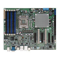
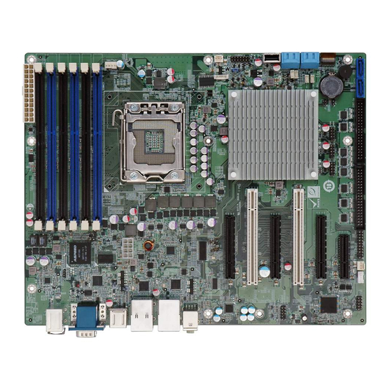
IEI Technology IMBA-C604EN User Manual (198 pages)
ATX server board supports 32nm LGA1356 Intel Xeon0 E5-2400 s eries up to 8 cores CPU with Intel C604, DDR3, VGA, PCIe Gen 3.0, Four SAS 3Gb/s , Two SATA 6Gb/s , Two SATA 6Gb/s , Ten COM and RoHS
Brand:
IEI Technology
| Category:
Motherboard
| Size: 8 MB
Table of Contents
Table of Contents
4
Introduction
16
1 Introduction
17
Introduction
17
Figure 1-1: IMBA-C604EN
17
Benefits
18
Features
18
Connectors
19
Figure 1-2: Connectors
19
Dimensions
20
Figure 1-3: IMBA-C604EN Dimensions (MM)
20
Data Flow
21
Figure 1-4: Data Flow Diagram
21
Technical Specifications
22
Table 1-1: IMBA-C604EN Specifications
23
2 Packing List
24
Anti Static Precautions
25
Unpacking Precautions
25
Packing List
26
Optional Items
27
Table 2-1: Packing List
27
Table 2-2: Optional Items
28
Connectors
29
3 Connectors
30
Peripheral Interface Connectors
30
IMBA-C604EN Layout
30
Figure 3-1: Connectors and Jumpers
30
Peripheral Interface Connectors
31
External Interface Panel Connectors
32
Table 3-1: Peripheral Interface Connectors
32
Table 3-2: Rear Panel Connectors
32
Internal Peripheral Connectors
33
ATX Power Connector
33
Figure 3-2: ATX Power Connector Pinout Location
33
Battery Connector
34
Chassis Intrusion Connector
34
Figure 3-3: Battery Connector Locations
34
Table 3-3: ATX Power Connector Pinouts
34
CPU Power Connector
35
Figure 3-4: Chassis Intrusion Connector Location
35
Table 3-4: Chassis Intrusion Connector Pinouts
35
DDR3 DIMM Slots
36
Figure 3-5: CPU Power Connector Location
36
Table 3-5: CPU Power Connector Pinouts
36
Digital I/O Connector
37
Figure 3-6: DDR3 DIMM Slot Locations
37
Figure 3-7: Digital I/O Connector Location
37
Fan Connector (CPU)
38
Figure 3-8: CPU Fan Connector Location
38
Table 3-6: Digital I/O Connector Pinouts
38
Fan Connector (System)
39
Figure 3-9: System Fan Connector Location
39
Table 3-7: CPU Fan Connector Pinouts
39
Table 3-8: System Fan Connector Pinouts (SYS_FAN1, SYS_FAN2)
39
Front Panel Audio Connector
40
Figure 3-10: Front Panel Audio Connector Location
40
Table 3-9: System Fan Connector Pinouts (SYS_FAN3, SYS_FAN4)
40
Table 3-10: Front Panel Audio Connector Pinouts
40
Front Panel Connector
41
Figure 3-11: Front Panel Connector Location
41
Table 3-11: Front Panel Connector Pinouts
41
I2C Connector
42
Figure 3-12: I2C Connector Location
42
Table 3-12: I2C Connector Pinouts
42
PCI Slots
43
Pcie X4 Slot
43
Figure 3-13: PCI Slot Locations
43
Pcie X8 Slot
44
SAS 3Gb/S Drive Connectors
44
Figure 3-14: Pcie X4 Slot Locations
44
Figure 3-15: Pcie X8 Slot Location
44
SAS LED Connector
45
Figure 3-16: SAS 3Gb/S Drive Connector Location
45
Table 3-13: SAS 3Gb/S Drive Connector Pinouts
45
SAS Smbus Connector
46
Figure 3-17: SAS LED Connector Location
46
Table 3-14: SAS LED Connector Pinouts
46
SATA 3Gb/S Drive Connectors
47
Figure 3-18: SAS Smbus Connector Location
47
Table 3-15: SAS Smbus Connector Pinouts
47
SATA 6Gb/S Drive Connectors
48
Figure 3-19: SATA 3Gb/S Drive Connector Location
48
Table 3-16: SATA 3Gb/S Drive Connector Pinouts
48
Serial Port Connector, RS-422/485
49
Figure 3-20: SATA 6Gb/S Drive Connector Location
49
Table 3-17: SATA 6Gb/S Drive Connector Pinouts
49
Serial Port Connectors, RS-232
50
Figure 3-21: RS-422/485 Connector Location
50
Table 3-18: RS-422/485Connector Pinouts
50
Figure 3-22: Serial Port Connector Location
51
Table 3-19: Serial Port Connector Pinouts
51
Smbus Connector
52
SPI ROM Connector
52
Figure 3-23: Smbus Connector Location
52
Table 3-20: Smbus Connector Pinouts
52
TPM Connector
53
Figure 3-24: SPI Connector Location
53
Table 3-21: SPI Connector Pinouts
53
USB Connectors
54
Figure 3-25: TPM Connector Location
54
Table 3-22: TPM Connector Pinouts
54
USB Connector (Type A)
55
Figure 3-26: USB Connector Pinout Locations
55
Table 3-23: USB Port Connector Pinouts( USB3, USB4, USBAB1)
55
External Peripheral Interface Connector Panel
56
Figure 3-27: USB Connector Pinout Locations
56
Figure 3-28: External Peripheral Interface Connector
56
Table 3-24: USB Port Connector Pinouts
56
Audio Connector
57
Ethernet and USB Connector
57
Figure 3-29: Audio Connector
57
Figure 3-30: Ethernet Connector
57
Table 3-25: Connector Leds
58
Table 3-26: LAN and USB Connector Pinouts (LAN1_USB3_1)
58
Keyboard/Mouse Connector
59
Table 3-27: LAN and USB Connector Pinouts (LAN2_USB01)
59
Table 3-28: USB Connector Pinouts (USB1)
59
Figure 3-31: Serial Port Connector Pinouts
60
Serial Port Connector
60
Table 3-29: PS/2 Connector Pinouts
60
Table 3-30: Serial Port Connector Pinouts
60
Figure 3-32: VGA Connector
61
Table 3-31: VGA Connector Pinouts
61
VGA Connector
61
4 Installation
62
Anti - Static Precautions
63
Installation Considerations
63
Socket LGA1356 CPU Installation
65
Figure 4-1: Disengage the CPU Socket Load Lever
65
Figure 4-2: Remove Protective Cover
66
Figure 4-3: Insert the Socket LGA1356 CPU
67
Figure 4-4: Close the Socket LGA1356
67
Socket LGA1356 Cooling Kit Installation
68
Figure 4-5: Cooling Kits (CF-1356A-RS, CF-1356B-RS)
68
Figure 4-6: Cooling Kit Support Bracket
69
DIMM Installation
70
Figure 4-7: DIMM Installation
70
Jumper Settings
71
AT/ATX Power Select Jumper
71
Table 4-1: Jumpers
71
Clear CMOS Jumper
72
Figure 4-8: AT/ATX Power Mode Jumper Location
72
Table 4-2: AT/ATX Power Mode Jumper Settings
72
Table 4-3: Clear BIOS Jumper Settings
72
Internal Peripheral Device Connections
73
SATA Drive Connection
73
Figure 4-9: Clear BIOS Jumper Location
73
Figure 4-10: SATA Drive Cable Connection
74
External Peripheral Interface Connection
75
Audio Connection
75
Figure 4-11: SATA Power Drive Connection
75
LAN Connection
76
Figure 4-12: Audio Connector
76
PS/2 Keyboard and Mouse Connection
77
Figure 4-13: LAN Connection
77
Serial Device Connection
78
Figure 4-14: PS/2 Keyboard/Mouse Connector
78
USB Connection
79
Figure 4-15: Serial Device Connector
79
VGA Monitor Connection
80
Figure 4-16: USB Connector
80
Figure 4-17: VGA Connector
81
Bios
82
5 Bios
83
Introduction
83
Starting Setup
83
Using Setup
83
Getting Help
84
Unable to Reboot after Configuration Changes
84
BIOS Menu Bar
84
Table 5-1: BIOS Navigation Keys
84
Main
85
Advanced
86
BIOS Menu 2: Advanced
86
ACPI Settings
87
RTC Wake Settings
87
BIOS Menu 3: ACPI Configuration
87
BIOS Menu 4: RTC Wake Settings
88
Trusted Computing
89
CPU Configuration
89
BIOS Menu 5: Trusted Computing
89
CPU Information
90
BIOS Menu 6: CPU Configuration
90
Runtime Error Logging
91
BIOS Menu 7: CPU Information
91
BIOS Menu 8: Runtime Error Logging
92
SATA Configuration
93
BIOS Menu 9: SATA Configuration
93
SAS Configuration
95
BIOS Menu 10: SAS Configuration
95
USB Configuration
96
BIOS Menu 11: USB Configuration
96
F81216 Second Super IO Configuration
97
Serial Port 7 Configuration
97
BIOS Menu 12: Secondary Super IO Configuration
97
Serial Port 8 Configuration
98
Serial Port 9 Configuration
98
Serial Port 10 Configuration
99
F81866 Super IO Configuration
100
BIOS Menu 13: Super IO Configuration
100
Serial Port N Configuration
101
BIOS Menu 14: Serial Port N Configuration Menu
101
F81866 H/W Monitor
106
BIOS Menu 15: Hardware Health Configuration
106
Smart Fan Mode Configuration
107
BIOS Menu 16: FAN 1 Configuration
108
Serial Port Console Redirection
110
BIOS Menu 17: Serial Port Console Redirection
111
Chipset
112
BIOS Menu 18: Chipset
112
North Bridge
113
BIOS Menu 19: Northbridge Chipset Configuration
113
South Bridge
114
BIOS Menu 20: Southbridge Chipset Configuration
114
ME Subsystem
115
Chipset Reference Board
116
BIOS Menu 21: ME Subsystem
116
BIOS Menu 22: Chipset Reference Board
117
Boot
118
BIOS Menu 23: Boot
118
Security
120
BIOS Menu 24: Security
120
Exit
121
BIOS Menu 25: Exit
121
6 Software Drivers
123
Available Software Drivers
124
Software Installation
124
Figure 6-1: Introduction Screen
125
Figure 6-2: Available Drivers
125
Chipset Driver Installation
126
Figure 6-3: Chipset Driver Screen
126
Figure 6-4: Chipset Driver Welcome Screen
127
Figure 6-5: Chipset Driver License Agreement
127
Figure 6-6: Chipset Driver Read Me File
128
Figure 6-7: Chipset Driver Setup Operations
128
Graphics Driver Installation
129
Figure 6-8: Chipset Driver Installation Finish Screen
129
Figure 6-9: Graphics Driver Welcome Screen
130
Figure 6-10: Graphics Driver License Agreement
130
Figure 6-11: Graphics Driver Setup Operations
131
Figure 6-12: Graphics Driver Installation Finish Screen
131
Lan Driver Installation
132
Figure 6-13: Windows Control Panel
132
Figure 6-14: System Control Panel
132
Figure 6-15: Device Manager List
133
Figure 6-16: Update Driver Software Window
134
Figure 6-17: Locate Driver Files
134
Figure 6-18: LAN Driver Installation
135
Figure 6-19: LAN Driver Installation Complete
135
Audio Driver Installation
136
Figure 6-20: Installshield Wizard Welcome Screen
136
Figure 6-21: Audio Driver Software Configuration
137
Figure 6-22: Restart the Computer
137
Sata Driver Installation
138
Figure 6-23: SATA RAID Driver Welcome Screen
138
Figure 6-24: SATA RAID Driver License Agreement
139
Figure 6-25: SATA RAID Driver Read Me File
139
Figure 6-26: SATA RAID Driver Setup Operations
140
Figure 6-27: SATA RAID Driver Installation Finish Screen
140
Usb 3.0 Driver Installation
140
Figure 6-28: USB 3.0 Driver Welcome Screen
141
Figure 6-29: USB 3.0 Driver License Agreement
142
Figure 6-30: USB 3.0 Driver Choose Install Location
142
Figure 6-31: USB 3.0 Driver Installation
143
Figure 6-32: USB 3.0 Driver Update Complete
143
A Bios Options
144
B One Key Recovery
147
One Key Recovery Introduction
148
Figure B-1: IEI One Key Recovery Tool Menu
148
System Requirement
149
Supported Operating System
150
Setup Procedure for Windows
151
Create Partitions
152
Hardware and BIOS Setup
152
Figure B-2: Launching the Recovery Tool
153
Figure B-3: Recovery Tool Setup Menu
153
Figure B-4: Command Prompt
154
Figure B-5: Partition Creation Commands
155
Install Operating System, Drivers and Applications
156
Building the Recovery Partition
157
Figure B-6: Launching the Recovery Tool
157
Figure B-7: Manual Recovery Environment for Windows
157
Figure B-8: Building the Recovery Partition
158
Figure B-9: Press any Key to Continue
158
Create Factory Default Image
159
Figure B-10: Press F3 to Boot into Recovery Mode
159
Figure B-11: Recovery Tool Menu
159
Figure B-12: about Symantec Ghost Window
160
Figure B-13: Symantec Ghost Path
160
Figure B-14: Select a Local Source Drive
161
Figure B-15: Select a Source Partition from Basic Drive
161
Figure B-16: File Name to Copy Image to
162
Figure B-17: Compress Image
162
Figure B-18: Image Creation Confirmation
163
Figure B-19: Image Creation Complete
163
Figure B-20: Image Creation Complete
163
Auto Recovery Setup Procedure
164
Figure B-21: Press any Key to Continue
164
Figure B-22: Auto Recovery Utility
165
Figure B-23: Launching the Recovery Tool
165
Figure B-24: Auto Recovery Environment for Windows
165
Figure B-25: Building the Auto Recovery Partition
166
Figure B-26: Factory Default Image Confirmation
166
Figure B-27: Image Creation Complete
167
Figure B-28: Press any Key to Continue
167
Setup Procedure for Linux
168
BIOS Menu 26: IEI Feature
168
Figure B-29: Partitions for Linux
169
Figure B-30: Manual Recovery Environment for Linux
170
Figure B-31: Access Menu.lst in Linux (Text Mode)
171
Figure B-32: Recovery Tool Menu
171
Recovery Tool Functions
172
Figure B-33: Recovery Tool Main Menu
172
Factory Restore
173
Figure B-34: Restore Factory Default
173
Backup System
174
Figure B-35: Recovery Complete Window
174
Figure B-36: Backup System
174
Figure B-37: System Backup Complete Window
175
Figure B-38: Restore Backup
175
Restore Your Last Backup
175
B.5.4 Manual
176
Figure B-39: Restore System Backup Complete Window
176
Figure B-40: Symantec Ghost Window
176
Manual
176
Restore Systems from a Linux Server through Lan
177
Configure DHCP Server Settings
178
Configure TFTP Settings
179
Configure One Key Recovery Server Settings
180
B.6.4 Start the DHCP, TFTP and HTTP
181
Create Shared Directory
181
Start the DHCP, TFTP and HTTP
181
Setup a Client System for Auto Recovery
182
Other Information
185
B.7 O Ther I Nformation
185
Using AHCI Mode or Ali M5283 / VIA VT6421A Controller
185
System Memory Requirement
187
C Terminology
188
D Watchdog Timer
192
E Hazardous Materials Disclosure
195
Hazardous Materials Disclosure Table for Ipb Products Certified as R Ohs Compliant under 2002/95/Ec Without Mercury
196
P a G E X
198
Advertisement
Advertisement
Related Products
IEI Technology IMBA-C2160
IEI Technology IMBA-C2060
IEI Technology IMBA-C604EP
IEI Technology IMBA-C2260-i2
IEI Technology IMBA-C2360-i2
IEI Technology IMBA-C2460
IEI Technology IMBA-C2160-R10
IEI Technology IMBA-C2260
iEi Technology IMBA-Q454-R10
IEI Technology IMBA-ADL-H610
IEI Technology Categories
Motherboard
Touch Panel
Computer Hardware
Single board computers
Desktop
More IEI Technology Manuals
Login
Sign In
OR
Sign in with Facebook
Sign in with Google
Upload manual
Upload from disk
Upload from URL