
Related Manuals for R.V.R. Electronica TEX30LCD

Summary of Contents for R.V.R. Electronica TEX30LCD
- Page 1 TEX30LCD TEX50LCD TEX100LCD TEX150LCD TEX300LCD USER MANUAL VOLUME1 Manufactured by R.V.R ELETTRONICA S.p.A. Italy...
- Page 2 File Name: TEX30_50_100_150_300-LCD_ING_1.0.indb Version: Date: 29/11/2012 Revision History Date Version Reason Editor 29/11/2012 First Version J. H. Berti TEX30LCD TEX50LCD TEX100LCD TEX150LCD TEX300LCD - User Manual Version 1.0 © Copyright 2012 R.V.R. Elettronica SpA Via del Fonditore 2/2c - 40138 - Bologna (Italia) Telephone: +39 051 6010506 Fax: +39 051 6011104 Email: info@rvr.it Web: www.rvr.it All rights reserved Printed and bound in Italy. No part of this manual may be reproduced, memorized or transmitted in any form or by any means, electronic or mechanic, including photocopying, recording or by any informa- tion storage and retrieval system, without written permission of the ...
-
Page 3: Table Of Contents
Quick guide for installation and use 5.1 Preparation 5.2 First power-on and setup 5.3 Operation 5.4 Management Firmware 5.5 Optional Function 6. Identification and Access to the Modules 6.1 Identification of the Modules Working Principles 7.1 TEX30/50/00/50/300LCD Common Parts 7.2 TEX30LCD Different Parts 7.3 TEX50/100/50LCD Different Parts 7.4 TEX300LCD Different Parts User Manual Rev. 1.0 - 29/11/12... - Page 4 TEX30/50/100/150/300LCD ELETTRONICA This page was intentionally left blank User Manual Rev. 1.0 - 29/11/12...
-
Page 5: Preliminary Instructions
TEX30/50/100/150/300LCD ELETTRONICA IMPORTANT The symbol of lightning inside a triangle placed on the product, evidences the operations for which is necessary gave it full attention to avoid risk of electric shocks. The symbol of exclamation mark inside a triangle placed on the product, informs the user about the presence of instructions inside the manual that accompanies the equipment, im- portant for the efficacy and the maintenance (repairs). Make sure both are properly connected. 1. Preliminary Instructions Operation of this equipment in a residential area may cause radio interference, in which case the user may be required • General Warnings to take adequate measures. This equipment should only be operated, installed and The specifications and data contained herein are provided maintained by “trained” or “qualified” personnel who are familiar for information only and are subject to changes without prior with risks involved in working on electric and electronic circuits. notice. R.V.R. Elettronica S.p.A. disclaims all warranties, “Trained” means personnel who have technical knowledge of express or implied.While R.V.R. Elettronica S.p.A. equipment operation and who are responsible for their own attempts to provide accurate information, it cannot accept safety and that of other unqualified personnel placed under... -
Page 6: First Aid
TEX30/50/100/150/300LCD ELETTRONICA Units returned without a return authorisation may be rejected and sent back to the sender. • Do not stop chest compressions while giving artificial breathing. 4 Be sure to include a detailed report mentioning all problems you have found and copy of your original • Call for medical help as soon as possible. invoice (to show when the warranty period began) with the shipment. 3.1.2 If the victim is conscious Please send spare and warranty replacement parts orders to • Cover victim with a blanket. the address provided below. Make sure to specify equipment model and serial number, as well as part description and • Try to reassure the victim. quantity. •... -
Page 7: General Description
TEX30/50/100/150/300LCD ELETTRONICA 4. General Description The TEX30/50/100/150/300LCD, manufactured by R.V.R. Elettronica SpA, are exciters for Frequency Modulated audio broadcasting in a frequency modulation able to transmit in the band between 87.5 and 108 MHz, in step of 10 KHz, with an RF output power adjustable up to a maximum of 30, 50, 100, 150 and 300 W respectively into a 50 Ohm standard load. The TEX30/50/100/150/300LCD are designed to being contained into a 19” rack box of 2HE. 4.1 Unpacking The package contains: 1 TEX30LCD, TEX50LCD, TEX100LCD, TEX150LCD or TEX300LCD 1 User Manual 1 Mains power cables The following accessories are also available from Your R.V.R. Dealer: • Accessories, spare parts and cables 4.2 Features These exciters contain a low-pass filter that reduces the harmonic emission to provided for by international standards (CCIR, FCC or ETSI) and can be connected directly to the antenna. Two major features of TEX30/50/100/150/300LCD are compact design and user- friendliness. Design is based on a modular concept: the different functions are performed by modules that, for the most part, are connected through male and facilitates maintenance and module replacement. The RF power section of the TEX30LCD features a MOSFET module delivering up to 30W output power, the TEX50/100/150LCD features a MOSFET module delivering up to 150W output power, the TEX300LCD features a MOSFET module delivering up to 300W output power. - Page 8 TEX30/50/100/150/300LCD ELETTRONICA An LCD on the front panel and a push-button board provide for user interfacing with the microprocessor control system, which offers the following features: • Output power setup. • Operating frequency setup. • Power output enable/disable. • Power Good feature (User-selectable output power alarm threshold). • Measurement and display of transmitter operating parameters. • Communication with external devices such as programming or telemetry systems via RS232 serial interface or I Four LEDs on the front panel provide the following status indications: ON, LOCK, FOLDBACK and RF MUTE. The exciters have an input for the external 24 Vcc supply. This auxiliary supply source, that can be realized by the user with the help of rescue batteries, is automatically used in case of AC voltage absence.
-
Page 9: Frontal Panel Description
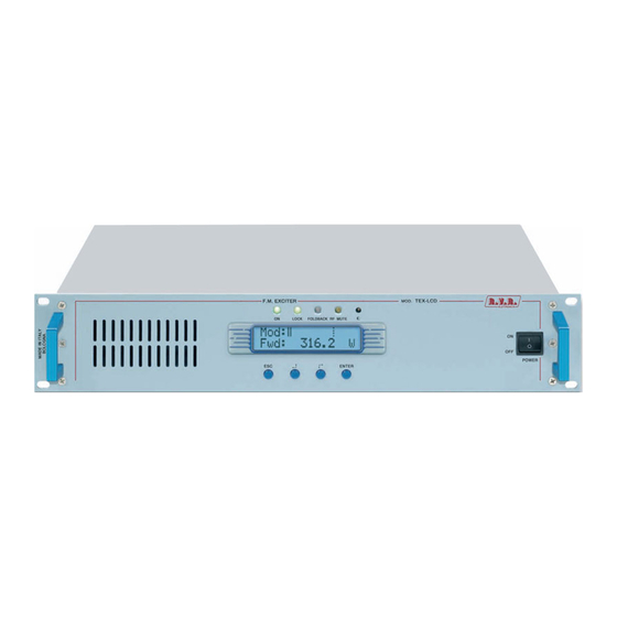
TEX30/50/100/150/300LCD ELETTRONICA 4.3 Frontal Panel Description [1] AIR FLOW Air flow for the forced ventilation. [2] ON Green LED, lit when the exciter is working. [3] LOCK Green led, lit when the PLL is locked on the working frequency. [4] FOLDBACK Yellow LED, lit when the foldback function is operating (automatic reduction of the delivered RF power). [5] R.F. MUTE Yellow LED, lit when the exciter’s power output is inhibited by an external interlock command. [6] CONTRAST Display contrast adjusting trimmer (on the top of the equipment). [7] ESC Push button to exit from a menu. [8] Push button to move in the menu system and to modify the parameters. [9] Push button to move in the menu system and to modify the parameters. [10] ENTER Push button to confirm a parameter and to enter in a menu. [11] DISPLAY Liquid crystals display. -
Page 10: Rear Panel Description
TEX30/50/100/150/300LCD ELETTRONICA 4.4 Rear Panel Description [1] PLUG VDE plug for mains supply. [2] VENTOLA Fan for the forced ventilation of the exciter. [3] R.F. OUTPUT RF output connector, N-type, 50Ω. [4] 24 VDC IN- External 24Vdc supply input. Negative (black). Only for TEX30/50/100/150LCD. [5] 24 VDC IN- External 24Vdc supply input. Positive (red). Only for TEX30/ 50/100/150LCD. [6] INTERLOCK OUT Connettore BNC di interlock in uscita: quando l’eccitatore entra in modalità stand-by, il conduttore centrale, normalmente flottante, viene posto a massa [7] FWD EXT. AGC Trimmer for the control of the delivered power in function of the FWD fold input. [8] RFL EXT. AGC Trimmer for the control of the delivered power in function of the RFL fold input. [9] REMOTE DB15 connector for telemetry of the machine. [10] GSM ANT Reserved for Future Uses - SMA connector for GSM Antenna. -
Page 11: Connectors Description
TEX30/50/100/150/300LCD ELETTRONICA while MPX input is unaffected by this setting. [27] 19 kHz PILOT OUT BNC output for the 19 kHz pilot tone. This can be used for external devices (e.g. RDS coders) synchronization. [28] SCA2 BNC connector, SCA2 unbalanced input. [29] SCA2 ADJ Adjustment trimmer for SCA2 input. [30] LEFT-MONO ADJ Adjustment trimmer for Left-Mono channel input. [31] LEFT-MONO XLR connector, balanced Left-Mono channel input. [32] IMPEDANCE Dip-switch to set the balanced input impedance, 600Ω or 10kΩ. 4.5 Connectors Description 4.5.1 RS232 Type: Female DB9 4.5.2 Service (for programming of factory parameters) Type: Female DB9 TX_D RX_D Internally connected with 6 Internally connected with 4 Internally connected with 8 Internally connected with 7 4.5.3 I C Bus Type: Male DB9 TX_D RX_D Internally connected with 6... - Page 12 TEX30/50/100/150/300LCD ELETTRONICA 4.5.4 Left (MONO) / Right Type: Female XLR Positive Negative 4.5.5 Remote Type: Female DB15 Pin Name Type Meaning Interlock By passes power if closed at GND Ext AGC FWD Ext. signal,1-12V, for power limitation (AGC) GND Ground SDA IIC I/O IIC communication serial data VPA Tlm ANL OUT PA power supply voltage 3,9V F.S. FWD Tlm ANL OUT Forward power 3,9V F.S. Power Good DIG OUT Open collector, enabled whenpower exceeds the set threshold GND Ground GND Ground 10 Ext AGC RFL Ext. signal.,1-12V, for power limitation (AGC) 11 SCL IIC...
-
Page 13: Technical Description
TEX30/50/100/150/300LCD ELETTRONICA 4.6 Technical Description TEX30LCD TEX50LCD TEX100LCD TEX150LCD TEX300LCD Parameters GENERALS Rated output power 100W 150W 300W Frequency range FCC -CCIR - OIRT - JPN Operational Mode Mono, Stereo, Multiplex Modulation type Primary Power 80 ÷ 260 Vac or 24 Vdc 115 / 230 ±15% or 28 Vdc... -
Page 14: Quick Guide For Installation And Use
5.1 Prepation 5.1.1 Preliminary checks Unpack the exciter and immediately inspect it for transport damage. Ensure that all connectors are in perfect condition. The main fuse can be accessed from the outside on the rear panel. Extract the fuse carrier with a screwdriver to check its integrity or for replacement, if necessary. The fuse to be used is this type: Fusibile principale TEX30LCD (1x) 3.15A tipo 5x20 @ 90÷260 Vac TEX50/100/150LCD (1x) 6.3A tipo 5x20 @ 230 Vac/115 Vac TEX300LCD (1x) 8A tipo 5x20 @ 230 Vac/115 Vac Table 5.1: Fuses... - Page 15 TEX30/50/100/150/300LCD ELETTRONICA √ For operating tests only: dummy load with 50 Ohm impedance and adequate capacity (30W for TEX30LCD, 50W for TEX50LCD, 100W for TEX100LCD, 150W for TEX150LCD or 300W for TEX300LCD as a minimum). √ Connection cable kit including: • Mains power cable • Coaxial cable with BNC connectors for interlock signal connection • RF cable for output to load / antenna (50 Ohm coaxial cable with N-type connector) • Audio cables between transmitter and audio sources. 5.1.2 Connections Connect the RF output of the transmitter to the antenna cable or a dummy load capable of dissipating amplifier output power. To begin with, set exciter to minimum output power and switch it off. Connect the transmitter INTERLOCK IN input to the matching INTERLOCK OUT output fitted on R.V.R. Elettronica equipment to act as hybrid couplers. If your equipment is a different brand, identify an equivalent output.
-
Page 16: First Power-On And Setup
TEX30/50/100/150/300LCD ELETTRONICA The exciter has two switches: one is embedded in VDE socket for mains power cord and interrupts all mains power supply of the machine, while the second is on the front panel and acts by inhibiting the switching power supply of the machine. Connect the mains power cable to the MAINS connector on the rear panel. Note: the mains must be equipped with adequate earth connection properly connected to the equipment. This is a pre-requisite for ensuring operator safety and correct operation. Connect the audio and RDS/SCA signals from user’s sources to the transmitter input connectors. 5.2 First power-on and setup Seguire le istruzioni riportate di seguito nel caso di prima accensione o dopo aver effettuato un cambiamento alla configurazione dell’eccitatore nel quale questo componente è integrato. - Page 17 TEX30/50/100/150/300LCD ELETTRONICA 5.2.4 Controllo del livello di potenza di uscita Note: The exciter incorporates Automatic Gain Control (AGC) and output power is modulated based on the power level set by the user and actual operating conditions, such as temperature, reflected power and other parameters. Please read section 5.3 for more details of RF power modulation.
-
Page 18: Operation
TEX30/50/100/150/300LCD ELETTRONICA Input sensitivity: Input Figure 6.2 Trimmer Sensitivity Notes SCA1/ [13] [16] - 8 ÷ +13 dBu Input level for 7,5 kHz overall deviation (- 20 dB) SCA2 [28] [29] - 8 ÷ +13 dBu MPX [14] [15] -13 ÷ +13 dBu Input level for 75 kHz overall deviation Left/ [31] [30] -13 ÷ +13 dBu Mono (0 dB) Right [18] [17] -13 ÷ +13 dBu When setting input sensitivity, please consider that the default menu reports instantaneous modulation level and an indicator provides a 75 kHz reading. To ensure correct adjustment, apply a signal with the same level as user’s audio broadcast maximum level and then adjust using the trimmer until instantaneous... - Page 19 (mod.TEX150LCD) ≅ 100W in uscita 100% potenza di uscita Barra piena (mod.TEX100LCD) ≅ 50W in uscita (mod.TEX50LCD) ≅ 30W in uscita (mod.TEX30LCD) ≅ 75W in uscita (mod.TEX300LCD) ≅ 700W in uscita (mod.TEX702LCD) ≅ 37,5W in uscita (mod.TEX150LCD) 1/4 della barra 25% potenza di uscita ≅...
-
Page 20: Management Firmware
TEX30/50/100/150/300LCD ELETTRONICA NOTE: This feature prevents the equipment from delivering maximum power as soon as output is enabled from menu 4, or in the event the equipment is already set to ON when you energise it. 2) Ensure that the equipment is not in a locked-out state. Press ESC to call up the selection screen (menu 3). Highlight Fnc and press ENTER to confirm and access the selected menu (menu 4). If PWR is set to OFF, i.e. power output is disabled, move cursor to PWR. Press ENTER and label will switch to ON, i.e. power output is enabled. Press ESC twice to go back to the default menu (menu 1). 3) Fine tune power setting from menu 2 (see description of item 1b) until achieving the desired value. WARNING: Equipment is capable of delivering more than rated output power (30/50/100/150/300 W for TEX30/50/100/150/300LCD respectively); however, never exceed the specified power rating. NOTE: If power is set to 0 W in the Power Setup Menu, the INTERLOCK OUT contact is activated and any external appliances connected to it are immediately inhibited. Next, you can review all operating parameters of the equipment through the management firmware. Normally, the equipment can run unattended. Any alarm condition is handled automatically by the safety system or is signalled by the LED indicators on the panel or by display messages. - Page 21 TEX30/50/100/150/300LCD ELETTRONICA Menu 2 Menu 1 Predefined menu Power Adjustment Menu Menu 3 Selection Menu Menu 4 Operation Menu Menu 5 Power Menu Menu 6 Power Amplifier Menu Menu 7 Settings Menu Menu 8 Miscellaneous Menu Menu 9 Versions Menu Menu 10 Channels Menu Figure 5.2 When the display is off, touching any key will turn on backlighting. When the display is on, pressing the ESC button from the default menu (menu 1) calls up the selection screen (menu 3), which gives access to all other menus: Menù 3 If the temperature alarm is enabled and the alarm threshold is exceeded, the following screen will be displayed (only if you are in the default screen): State 1 User Manual...
- Page 22 TEX30/50/100/150/300LCD ELETTRONICA As soon as operating conditions are restored, power output is re-enabled with the same settings in use prior to the alarm condition. Under 20kHz, no modulation occurs. After a preset time of about 5 minutes (not editable), a NO AUDIO condition is indicated in the main screen, but power is not inhibited. State 2 To gain access to a submenu, select menu name (name is highlighted by cursor) using button or and press the ENTER button. To return to the default menu (menu 1), simply press ESC again. 5.4.1 Operation Menu (Fnc) In this menu, you can toggle exciter power output On/Off, set deviation display mode and the threshold rate for Forward (PgD) or Reflected (PgR) Power Good. To edit an item, highlight the appropriate line using the and buttons and then press and hold the ENTER button until the command is accepted.
- Page 23 TEX30/50/100/150/300LCD ELETTRONICA Modifies modulation display (toggles between “x1” and “x10”). In “x10” mode, instantaneous deviation indication is multiplied by a factor of 10, and the bar meter on the default menu will reflect 7.5 kHz instead of 75 kHz. This display mode is convenient when you wish to display low deviation levels, such as those caused by pilot tone or subcarriers. Modifies Power Good threshold for forward power. The Power Good rate is a percent of equipment rated power (30/50/100/150/300 W for TEX30/50/100/150/300LCD respectevely), not of forward output power. This means that this threshold set at 50% will give 15/25/50/75/150 W, respectively, regardless of set power level. The Power Good feature enables output power control and reporting. When output power drops below set Power Good threshold, the equipment changes the state of pin [7] of the DB15 “Remote” connector located on the rear panel. Modifies Power Good threshold for reflected power. The Power Good rate is a percent of equipment rated power (3/5/10/15/30 W for TEX30/ 50/100/150/300LCD respectevely), not of reflected output power. This means that this threshold set at 5% will give 0,15/0,25/0,50/0,75/1,5 W, respectively, regardless of set power level. The Power Good feature enables output power control and alarm management. NOTE: This alarm does not trip any contacts in the DB15 “Remote” connector and is only available in systems equipped with telemetry. 5.4.2 Power menu(Pwr) This screen holds all readings related to equipment output power: Menu 5 Forward power reading. Reflected power reading. Note that these are readings, rather than settings, and cannot be edited (note the empty triangle). To change power setting, go to the default menu as outlined earlier.
- Page 24 TEX30/50/100/150/300LCD ELETTRONICA 5.4.3 Power Amplifier (P.A) Menu This screen is made up of four lines that can be scrolled using the and buttons and shows the readings relating to final power stage: Menu 6 Note that these are readings, rather than settings, and cannot be edited (note the empty arrow). Voltage supplied by amplifier module. Current draw of amplifier module. Efficiency based on ratio of forward power to amplifier module power, in percent ( FWD PWR/(Vpa x Ipa) % ). Equipment internal temperature reading. 5.4.4 Setup Menu (Set) This menu lets you view and set operating frequency. Menu 7 Operating frequency setup. Set a new frequency value and then press the ENTER button to confirm your selection; the exciter unlocks from current frequency (the LOCK LED turns off) and will lock to the new operating frequency (LOCK turns back on again). If you press ESC or let the preset time time out, the previous frequency setting is retained. User Manual / 32 Rev. 1.0 - 29/11/12...
- Page 25 TEX30/50/100/150/300LCD ELETTRONICA 5.4.5 Miscellaneous Menu (Mix) This menu lets you set equipment address in an I C bus serial connection: Menu 8 IIC C address setting. The I2C network address becomes significant when the exciter is connected in an RVR transmission system that uses this protocol. Do not change it unless strictly required. 5.4.6 Version Menu (Vrs) This screen holds equipment version/release information: Menu 9 Note that these are readings, rather than settings, and cannot be edited (note the empty arrow). Firmware release information. Release date. Shows table loaded in the memory. 5.4.7 Channels Menu (L&R) Right and left channel input levels are displayed as horizontal bars as shown in the figure below. The bar meter reflects the level corresponding to a 100% deviation for each channel and provides a convenient reference when setting audio channel input levels. Menù 10 Left channel Vmeter. Right channel Vmeter.. User Manual Rev. 1.0 - 29/11/12 / 32...
-
Page 26: Optional Function
TEX30/50/100/150/300LCD ELETTRONICA 5.5 Optional Function A range of options is available for the product to add certain functions and/or modify existing functions. Outlined below are the functions available at the moment, which must be specified on order. 5.5.1 FSK Option The FSK function generates periodic carrier frequency shifts to generate a Morsecoded station ID code. NOTE: This function is typically used in the USA. The factory setting for frequency shift is +10KHz and code repetition period is 60 minutes (please contact R.V.R. Elettronica if you need different settings), whereas station identified may be programmed by the user following the indications provided in section below. When the FSK option is fitted, an FSK submenu is added to the selection menu. - Page 27 TEX30/50/100/150/300LCD ELETTRONICA A brief description of the procedure is provided below: • Connect the PC serial port COM to the SERVICE connector on the rear panel of TEX30/50/100/150/300LCD using a standard Male DB9 - Female DB9 serial cable. • Power on the exciter; • Launch the serial communication software; • Set communication parameters as follows: Baud Rate: 19200 Data Bit: 8 Parity: None Stop Bit: 1 Flow control: None; • Activate Caps-Lock through the communication software and send string CODE followed by the 6-character station ID code followed by Enter. NOTE: To be treated as valid, the code must be made up of 6 alphanumeric characters and must contain no blank spaces; if acknowledged as valid, code is echoed back to the terminal, illegal codes are not echoed. 5.5.2 Power UP/DOWN Option The Power UP/DOWN option modifies the signal receive function for the signals present at the telemetry connector.
-
Page 28: Identification And Access To The Modules
TEX30/50/100/150/300LCD ELETTRONICA 6. Identification and Access to the Modules 6.1 Identification of the Modules The TEX30/50/100/150/300LCD is made up of various modules linked to each other through connectors so as to make maintenance and any required module replacement easier. 6.1.1 TEX30LCD Upper view The figure below shows the equipment upper view with the various components pointed out. figure 8.1 [1] Main Board & Stereo Coder Card [2] Panel Card [3] Telemetry Card [4] Control Card& Power Amplifier [5] Power Supply User Manual / 32 Rev. 1.0 - 29/11/12... - Page 29 TEX30/50/100/150/300LCD ELETTRONICA 6.1.2 TEX50/100/150LCD Upper view The figure below shows the equipment upper view with the various components pointed out. figure 8.2 [1] Main Board & Stereo Coder Card [2] Panel Card [3] Telemetry Card [4] Control Card& Power Amplifier [5] Power Supply User Manual Rev. 1.0 - 29/11/12 / 32...
- Page 30 TEX30/50/100/150/300LCD ELETTRONICA 6.1.3 TEX300LCD Upper view The figure below shows the equipment upper view with the various components pointed out. figure 8.3 [1] Main Board & Stereo Coder Card [2] Panel Card [3] Telemetry Card [4] Control Card& Power Amplifier [5] Power Supply User Manual / 32 Rev. 1.0 - 29/11/12...
-
Page 31: Working Principles
TEX30/50/100/150/300LCD ELETTRONICA 7. Working Principles 7.1 TEX30/50/100/150/300LCD Common Parts 7.1.1 Panel board The panel board contains the microcontroller (PIC18F452) that implements the equipment control software, the display and the other components needed to interface with the user. The board is connected with the other machine modules, both for power supply distribution and for the control and measures. 7.1.2 Main board The main board carries out the following functions: • Audio and SCA input treatment • Generation of carrier frequency • Modulation • R.F. amplification (Driver) The board also features a stereophonic coder. 7.1.2.1 Audio input section The audio input section contains the circuits that perform the following functions: • Input impedance selection • 15 kHz filtering of the left and right channel... -
Page 32: Tex30Lcd Different Parts
7.1.3 Telemetry board This board is designed to inform the user of the equipment operation state. All input and output signals are available on the DB15 connector. The same board also features the “INTERLOCK” BNC connector for disabling the device. By grounding the central pin, the output power is reduced to zero until the connection is removed. When an R.V.R. amplifier is used, this connector is linked to the power amplifier REMOTE or INTERLOCK by means of a BNC-BNC connection. In case of amplifier faults, the central conductor is grounded thus forcing the machine to enter in stand-by mode. 7.2 TEX30LCD Different Parts 7.2.1 Power Supply The TEX30LCD power supply unit is a switching-type unit whose +28 V main output powers the machineÌs RF amplifier. The power supply also features stabilizers for generating continuous +5 V and +18 V voltages for supplying the other equipment circuits. Note that the power supply is a “direct from mains” type, or rather it is without a transformer, and it can be connected to any voltage between 80 and 260 V without any adjustments or manual settings. The power supply unit is also connected to 24 V auxiliary continuous voltage inputs used to automatically buffer the mains power cutoff. 7.2.2 Power Amplifier The final power stage is enclosed in a totally shielded metal container fastened in the centre of the device. -
Page 33: Tex50/100/50Lcd Different Parts
TEX30/50/100/150/300LCD ELETTRONICA • Control of the power level in output, depending on the setting • Reduction of the power supplied when in presence of high-level reflected power • Measures of the forward and reflected power by means of directional couplers • Measures of the current absorbed by the power amplifier • Measures of the temperature • Low-pass filtering of the RF signal in output This board also features an RF sampling of approximately -30dB RF with respect to the output, which is available on a BNC connector below the transmitter output connector. This sample is is useful for verifying the characteristics of the carrier, but not for verifying those of the upper harmonics. - Page 34 TEX30/50/100/150/300LCD ELETTRONICA 7.3.2 Power Amplifier The final power stage is enclosed in a totally shielded metal container fastened in the centre of the device. The RF signal coming from the “main” card reaches the pilot, is amplified and is then sent to the final stage that sees to its final amplifications up to 150W. The amplifier is made in two stages. The first is made with BLF244 and the last with BLF147. In addition to the actual RF amplification, this circuit carries out the following functions: • Control of the power level in output, depending on the setting • Reduction of the power supplied when in presence of high-level reflected power • Measures of the forward and reflected power by means of directional couplers • Measures of the current absorbed by the power amplifier...
-
Page 35: Tex300Lcd Different Parts
TEX30/50/100/150/300LCD ELETTRONICA 7.4 TEX300LCD Different Parts 7.4.1 Power Supply The TEX300LCD power supply unit is a switching-type unit whose +50 V main stabilizers for generating continuous +5 V, +18 V and -18 V voltages for supplying the other equipment circuits. Note that the power supply is a “direct from mains” type, or rather it is without a transformer, and it can be connected to any voltage between 90 and 260 V without any adjustments or manual settings. 7.4.2 Power Amplifier The final power stage is enclosed in a totally shielded metal container fastened in the centre of the device. The RF signal coming from the “main” card reaches the pilot, is amplified and is then sent to the final stage that sees to its final amplifications up to 300W. The amplifier is made in three stages. The first is made with BFG35, the second with one BLF175 and the last with one SD2942. In addition to the actual RF amplification, this circuit carries out the following functions: • Control of the power level in output, depending on the setting • Reduction of the power supplied when in presence of high-level reflected power • Measures of the forward and reflected power by means of directional couplers... - Page 36 TEX30/50/100/150/300LCD ELETTRONICA power, with a feedback mechanism based on the reading of the power really delivered (AGC). The voltage is also affected by other factors, such as: • Excess of reflected power. • External AGC signals (Ext. AGC FWD, Ext. AGC RFL). • Excess of temperature. • Excess of absorbed current from the RF module. User Manual / 32 Rev. 1.0 - 29/11/12...
- Page 37 ______________________________________________________________________________ ______________________________________________________________________________ ______________________________________________________________________________ ______________________________________________________________________________ ______________________________________________________________________________ ______________________________________________________________________________ ______________________________________________________________________________ ______________________________________________________________________________ ______________________________________________________________________________ ______________________________________________________________________________ ______________________________________________________________________________ ______________________________________________________________________________ ______________________________________________________________________________ ______________________________________________________________________________ ______________________________________________________________________________ ______________________________________________________________________________ ______________________________________________________________________________ ______________________________________________________________________________ ______________________________________________________________________________ ______________________________________________________________________________ ______________________________________________________________________________ ______________________________________________________________________________ ______________________________________________________________________________ ______________________________________________________________________________ ______________________________________________________________________________...
- Page 38 ______________________________________________________________________________ ______________________________________________________________________________ ______________________________________________________________________________ ______________________________________________________________________________ ______________________________________________________________________________ ______________________________________________________________________________ ______________________________________________________________________________ ______________________________________________________________________________ ______________________________________________________________________________ ______________________________________________________________________________ ______________________________________________________________________________ ______________________________________________________________________________ ______________________________________________________________________________ ______________________________________________________________________________ ______________________________________________________________________________ ______________________________________________________________________________ ______________________________________________________________________________ ______________________________________________________________________________ ______________________________________________________________________________ ______________________________________________________________________________ ______________________________________________________________________________ ______________________________________________________________________________ ______________________________________________________________________________ ______________________________________________________________________________ ______________________________________________________________________________...
- Page 39 ______________________________________________________________________________ ______________________________________________________________________________ ______________________________________________________________________________ ______________________________________________________________________________ ______________________________________________________________________________ ______________________________________________________________________________ ______________________________________________________________________________ ______________________________________________________________________________ ______________________________________________________________________________ ______________________________________________________________________________ ______________________________________________________________________________ ______________________________________________________________________________ ______________________________________________________________________________ ______________________________________________________________________________ ______________________________________________________________________________ ______________________________________________________________________________ ______________________________________________________________________________ ______________________________________________________________________________ ______________________________________________________________________________ ______________________________________________________________________________ ______________________________________________________________________________ ______________________________________________________________________________ ______________________________________________________________________________ ______________________________________________________________________________ ______________________________________________________________________________...
- Page 40 ISO 9001:2000 certified since 2000 R.V.R Elettronica S.p.A. Via del Fonditore, 2 / 2c Zona Industriale Roveri · 40138 Bologna · Italy Phone: +39 051 6010506 · Fax: +39 051 6011104 e-mail: info@rvr.it ·web: http://www.rvr.it The RVR Logo, and others referenced RVR products and services are trademarks of RVR Elettronica S.p.A. in Italy, other countries or both. RVR ® 1998 all rights reserved. All other trademarks, trade names or logos used are property of their respective owners.
Need help?
Do you have a question about the TEX30LCD and is the answer not in the manual?
Questions and answers