Viper AS430C User Manual
Hide thumbs
Also See for AS430C:
- User manual (288 pages) ,
- User manual (234 pages) ,
- User manual (29 pages)

Related Manuals for Viper AS430C


Summary of Contents for Viper AS430C
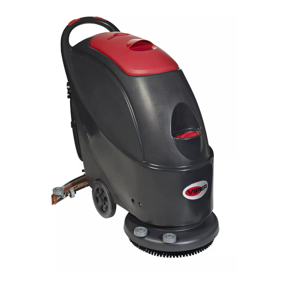
- Page 1 Scrubber User Manual AS430C VIPER NORTH AMERICA [866] 418-4737 [866] 41-VIPER VF90031-US Rev.01...
-
Page 2: Table Of Contents
USER MANUAL TABLE OF CONTENTS INTRODUCTION ..............................2 CONTENTS . . . . . . . . . . . . . . . . . . . . . . . . . . . . . PURPOSE . . . . . . . . . . . . . . . . . . . . . . . . . . . . . SPARE PARTS AND MAINTENANCE .... -
Page 3: Introduction
The information includes technical data, safety, operation, storage, maintenance and disposal of the machine. All operators and technicians should study this manual carefully before prior to operating or servicing the machine. Please contact your local Viper distributor with any questions. -
Page 4: Technical Data
Viper distributor. In order to ensure safe and proper operation of the machine, it is advised that your Viper authorized service provider perform the scheduled maintenance according to the maintenance schedules outlined in this manual. -
Page 5: Machine Description
USER MANUAL MACHINE DESCRIPTION MACHINE EXPLODED VIEW Safety switch button 20. Squeegee adjusting knob Handle 21. Squeegee rear support frame Control panel 22. Squeegee front support frame Serial number plate/Technical data 23. Cup holder Control cover 24. Recovery tank cover handle 25. -
Page 6: Control Panel
“off” position and lift the squeegee off the floor. Only after which can the brush or pad-holder be worked on. Always wear protective gloves. 1. (Only applicable to AS430C ): make sure the power cable (9) disconnecting the power supply and the switch (38) is at the disconnecting (Off) condition. -
Page 7: Regulating Water Flow
USER MANUAL whole length of the rear squeegee strip touches well with the floor. The front squeegee strip should lightly touch the floor. 2) If the two ends of the rear squeegee strip, sections C and D, have a gap with the floor or the downward pressure is relatively light, adjust the handle in a clockwise direction until the whole length of the rear squeegee strip touches well with the floor. -
Page 8: Machine Operation
USER MANUAL CONSULTATION : : : : Each safety switch capable controlling independently the operation of the brush. In use, facilitates the control of the operation of the machine. Operators are encouraged to find the most comfortable position their hands. Turning off the machine When you have finished using the machine, first remove the Figure 6... -
Page 9: After Each Use
Prior to proceeding with any of the maintenance procedures, please study carefully the related safety sections. All maintenance should be done by qualified personnel or authorized Viper service centers. This manual only relates the simplest and the most common maintenance procedures. -
Page 10: Scheduled Maintenance Table
Inspect or change carbon brush of Vacuum motor (1) It should be done 9 hours after the machine starts working. (2) These maintenance procedures must be done by an authorized VIPER Service Center. SQUEEGEE CLEANING NOTE In order to maintain the optimal squeegee performance, the squeegee must be kept clean, and the squeegee blades must remain in good condition. -
Page 11: Brush/ Pad Cleaning
USER MANUAL Loosen the handle screw (I) and take off the front clip bar (L), and then change the front - squeegee (C). Re-install the front squeegee blade in the reverse order of taking it off. After changing the squeegee blade, adjust the level of the front and rear squeegee blades in the procedures as described above. -
Page 12: Solution Filter Cleaning
USER MANUAL connector to the middle section of the rear part. 7. Check if the receiving surface of the sealing strip (G) is intact and seals adequately. 8. Close recovery tank lid (A). Figure 11 SOLUTION FILTER CLEANING 1. Drain all the water from Solution tank as previously outlined. 2. -
Page 13: Troubleshooting
USER MANUAL TROUBLESHOOTING Breakdown Probable Causes Remedies The wiring not connected correctly or Check the wiring or contact Viper bad wiring Distributor Machine not working Bad brush motor Contact Viper Distributor Carbon brush worn out Contact Viper Distributor The wiring not connected correctly or... -
Page 14: Part Breakdowns And Lists
TANK SYSTEM AS430C PART LIST... - Page 16 TANK SYSTEM AS430C PART LIST Item Part No. Description VF13604 GROOVED METAL GASKET VF90235 SCEREW TM4x10 VF90508 SUCTION HOSE VF90231 GASKET VF90214 SEAL PLATE COVER VF90217 SEAL PLATE VA80758 SCREW VF90529 SUCTION TUBE CONNECTER VF90528 DRAIN HOSE CONNECTOR VF90512 SUCTION TUBE GASKET...
- Page 17 CONTROL SYSTEM AND ELECTRICAL SYSTEM AS430C PART LIST...
- Page 18 CONTROL SYSTEM AND ELECTRICAL SYSTEM AS430C PART LIST Item Part No. Description VF90203 SAFETY SWITCH KNOB VF90286 SCREW KA3.5x12 VF90201 SAFETY SWITCH COVER LEFT VV68303 SCREW KA3.5x15 VF90288 WASHER Φ3.6XΦ8X0.5 VF90210 SWITCH FIX FRAME VV60153 SWITCH RL2 ( ) VF90009...
- Page 19 CONTROL SYSTEM AND ELECTRICAL SYSTEM AS430C PART LIST Item Part No. Description VF90128 SCREW M5 VF90114 CABLE SQUEEGEE LIFT VF89076 CIRCUIT BREAKER CAP 80407A SCREW M5X25 VF90116 HAND BRACKET VF90704 24V RELAY VV13652 NUT LOCK M3 VV13653 WASHER Ø3.4xØ10x1.0mm VF90232...
- Page 20 WHEELS AND SOLUTION SYSTEM AS430C PART LIST...
- Page 22 BRUSH SYSTEM AS430C PART LIST...
- Page 23 BRUSH SYSTEM AS430C PART LIST Item Part No. Description VF90729 BRUSH MOTOR KIT VF90284 SOLENOID VALVE KIT VF90418 SOLENOID VALVE BRACKET VV13650A SCREW M4x10 VV20274 WASHER VF90460 CONNECT PLATE C VF90461 BRASS SPACER B VF90421 SPACER VF14555 SCREW,SHOULDER M12x50 VF14238...
- Page 24 BRUSH SYSTEM AS430C PART LIST Item Part No. Description VF13503 NUT LOCK M8 VF14057A NUT LOCK M12 VF90459 SLIDING CONNECT PLATE VF90455 FRAME VF13538 WASHER φ12xφ24x2 VF13541 WASHER,LOCK ¢ VV20298 WASHER,LOCK,Ø8 VA13491 SCREW, M8x25 VF90445 TENSION WHEEL KIT VF14516 NUT LOCK M8...
- Page 25 SQUEEGEE SYSTEM AS430C PART LIST...
- Page 26 SQUEEGEE SYSTEM AS430C PART LIST Item Part No. Description VF14547 SCREW LOCK M10 VF85104 HAND WHEEL VF13534 WASHER φ8.4x φ18x 2 VF14503 NUT M8 VF90133 SPACER VF90110 BACK-SQUEEGEE-SUPPORT VF14516 NUT LOCK M8 VF14506 NUT M6 VF13533 WASHER FLAT Ø6 VF90111...
- Page 27 SQUEEGEE SYSTEM AS430C PART LIST Item Part No. Description VF90101 SQUEEGEE 17" VF90127 SQUEEGEE SCREW VF90138 17" STRAP S QUEEGEE BACK KIT , VF14305 SCREW M5×60 VF90121 HOOK VF81208A RIVET Ø4×5 VF81218A LATCH HOOD GT13022 NUT LOCK M5 VF90105 17" STRAP S QUEEGEE BACK ,...
-
Page 28: Wiring Diagram
WIRING DIAGRAM AS430C PART LIST... - Page 29 Company information: www.usviper.com...
Need help?
Do you have a question about the AS430C and is the answer not in the manual?
Questions and answers