Viper AS510B User Manual
Hide thumbs
Also See for AS510B:
- User manual (368 pages) ,
- Use and maintenance (2 pages) ,
- User manual (387 pages)

Related Manuals for Viper AS510B


Summary of Contents for Viper AS510B
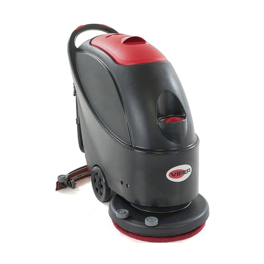
- Page 1 Scrubber User Manual AS510B VIPER NORTH AMERICA [866] 418-4737 [866] 41-VIPER VF90029-US Rev.01...
-
Page 2: Table Of Contents
USER MANUAL TABLE OF CONTENTS INTRODUCTION ..............................2 CONTENTS . . . . . . . . . . . . . . . . . . . . . . . . . . . . . PURPOSE . . . . . . . . . . . . . . . . . . . . . . . . . . . . . SPARE PARTS AND MAINTENANCE .... -
Page 3: Introduction
The information includes technical data, safety, operation, storage, maintenance and disposal of the machine. All operators and technicians should study this manual carefully before prior to operating or servicing the machine. Please contact your local Viper distributor with any questions. -
Page 4: Safety Guides
Viper distributor. In order to ensure safe and proper operation of the machine, it is advised that your Viper authorized service provider perform the scheduled maintenance according to the maintenance schedules outlined in this manual. -
Page 5: Technical Data
USER MANUAL TECHNICAL DATA Model AS510B Machine Height 980mm Solution tank capacity 40 litre Recovery tank capacity 40 litre Diameter of transport wheel 200mm Diameter of guide wheel 76mm Power of vacuum system motor 350w Maximum gradient when working %... -
Page 6: Control Panel
Figure 1 CONTROL PANEL (Figure2) 38. Battery charge indication light (green when saturated) Battery exhausted indication light (red) 40. Battery exhausted indication light (red) 41. Power switch 42. Vacuum switch 43. Hour meter (optional) 44. Solution switch AS510B Figure 2... -
Page 7: Charger Indication Light
USER MANUAL CHARGER INDICATOR LIGHTS (Figure 3) (Optional, applicable to models with built-in charger) 1. When charging starts, the red indication light (45) flashes a few times and then steadies to become a permanent red indication light, entering into the first stage of charging. 2. - Page 8 USER MANUAL IF YOU NEED TO REPLACE THE BATTERIES 1. Contact your local authorized Viper distributor for proper batteries. 2. Set the machine and the on-board charger (if equipped) according to the type of batteries (WET or GEL/AGM). Follow battery installation instructions as outlined below.
-
Page 9: Before Machine Start-Up
USER MANUAL 14. Install the battery with specially made battery installation tools (A, Figure 7). After the battery is installed, remove the battery installation tools, and install the battery fixation bracket (B, Figure 7). Figure 7 15. Put the battery connector (C, Figure 7) through the hole on the top of the battery box cover, put the drain hose through the right hole of the battery box cover, attach the battery box cover with 4 screws, and then install the squeegee lift cable, drain hose, and the squeegee successively. -
Page 10: Regulating Water Flow
USER MANUAL Figure 9 Solution tank filling CAUTION ! ! ! ! Only low foam, nonflammable detergents may be used. These detergents must be suitable for the use of scrubbers. 9. Open the water inlet cover (27) and add water to solution tank. Do not overfill the tank. When preparing the cleaning solutions, please follow the dilution rates supplied by the chemical manufacturer Water temperature must not exceed 40 REGULATING WATER FLOW... -
Page 11: Machine Operation
USER MANUAL Turning off the machine When you have finished using the machine, first remove the brush/pad-holder (refer to the steps mentioned above) Release the safety switch (1) to turn off the brush/pad- holder and solenoid valve. Press the Vacuum switch (42) to the “Off” position, and the Vacuum will delay for 5 seconds before stopping work. -
Page 12: After Each Use
USER MANUAL recovery tank cover (25), and press the power switch (41 and 42) to turn on the main power and the vacuum motor. Recovery tank emptying 1. Turn off the machine. 2. Raise the squeegee assembly (14). 3. Move the machine to a dedicated draining location. 4. -
Page 13: Maintenance And Care
All maintenance should be done by qualified personnel or authorized Viper service centers. This manual only relates the simplest and the most common maintenance procedures. For any maintenance procedures other than those stated in this table of planned maintenance, please contact your local Viper distributor. -
Page 14: Squeegee Cleaning
USER MANUAL WARNING ! ! ! ! Particular care must be taken when charging the battery because there may be leakage of acid during the charging process. Battery acid is corrosive. If contact is made with skin or eyes, please flush with clean water and seek medical attention. 1. -
Page 15: Squeegee Blade Check And Replacement
USER MANUAL the rear squeegee blade (D) are intact, and if there are broken edges and cracks. Replace them if necessary (refer to the steps in the following section). 6. Re-install the squeegee in the reverse order of the above SQUEEGEE BLADE CHECK AND REPLACEMENT 1. -
Page 16: Water Tank And Float Filter Mesh Cleaning
USER MANUAL WATER TANK AND FLOAT FILTER MESH CLEANING Move the machine to a dedicated draining area. 2. Press the power switch (41) to the position “O” to turn off the machine. 3. Open recovery tank lid (A, Figure 16), and remove the float device (36) from inside the tank. 4. -
Page 17: Troubleshooting
USER MANUAL NOTE The filter (E) must be accurately installed onto the position of the housing (G). 6. Open the draining ball valve (A). Filter Mesh Mark Figure TROUBLESHOOTING Breakdown Probable Cause Remedies Battery connector (9) not connected. Connect the battery connector Machine not working: Indication light not on Battery power already exhausted... -
Page 18: Part Breakdowns And Lists
TANK SYSTEM AS510B PART LIST... - Page 20 TANK SYSTEM AS510B PART LIST Item Part No. Description VF90235 SCEREW TM4x10 VF90508 SUCTION HOSE VF90246 BATTERY CABLE KIT VF90231 GASKET VF90214 SEAL PLATE COVER VF90217 SEAL PLATE VA80758 SCREW VF90529 SUCTION TUBE CONNECTER VF90528 DRAIN HOSE CONNECTOR VF90512 SUCTION TUBE GASKET...
- Page 21 CONTROL SYSTEM AND ELECTRICAL SYSTEM AS510B PART LIST...
- Page 22 CONTROL SYSTEM AND ELECTRICAL SYSTEM AS510B PART LIST Item Part No. Description VF90203 SAFETY SWITCH KNOB VV68303 SCREW KT3.5x15 VF90201 SAFETY SWITCH COVER LEFT VF90286 SCREW KA3.5x12 VF90288 WASHER Φ3.6XΦ8X0.5 VF90210 SWITCH FIX FRAME VV60153 SWITCH RL2 ( ) VF90008 20"...
- Page 23 CONTROL SYSTEM AND ELECTRICAL SYSTEM AS510B PART LIST Item Part No. Description GT13091 SCREW PB3.5x9.5 VF90238-1 17" CONTROL CIRCUIT BOARD VF90209 PCB HOUSING VF90237 NYLON CABLE HOOK VF90221 NYLON CABLE VF14514 NUT LOCK M5 VF90259 HAND FIX PANEL ZD48320 CIRCUIT BREAKER...
- Page 24 WHEELS AND SOLUTION SYSTEM AS510B PART LIST...
- Page 26 BRUSH SYSTEM AS510B PART LIST...
- Page 27 BRUSH SYSTEM AS510B PART LIST Item Part No. Description VF90257 20" BRUSH MOTOR VF90424 NUT M20 VF90282 SOLENOID VALVE KIT VF90418 SOLENOID VALVE BRACKET VV13650A SCREW M4x10 VV10114 CLAMP VF90440 TUBING L=260mm VF90430 BRASS SPACER VF90404 CONNECT PLATE VF90421 SPACER...
- Page 28 BRUSH SYSTEM AS510B PART LIST Item Part No. Description VF13503 NUT LOCK M8 VF14057A NUT , M12 VF13541 WASHER,LOCK Ø12 VF13538 WASHER ,Ø12xØ24x2 VF90456 CONNECT PLATE B VF90403 20" FRAME VV20298 WASHER,LOCK,Ø8 VV13604 SCREW, M8x20 VF90445 TENSION WHEEL KIT VF14516...
- Page 29 SQUEEGEE SYSTEM AS510B PART LIST...
- Page 30 SQUEEGEE SYSTEM AS510B PART LIST Item Part No. Description VF14547 SCREW LOCK M10 VF85104 HAND WHEEL VF13534 WASHER φ8.4x φ18x 2 VF14503 NUT M8 VF90133 SPACER VF90110 BACK-SQUEEGEE-SUPPORT VF14516 NUT LOCK M8 VF14506 NUT M6 VF13533 WASHER FLAT Ø6 VF90111...
- Page 31 SQUEEGEE SYSTEM AS510B PART LIST Item Part No. Description VF90117 SQUEEGEE 20" VF90127 SQUEEGEE SCREW VF90139 20" STRAP S QUEEGEE BACK KIT , VF14305 SCREW M5×60 VF90121 HOOK VF81208A RIVET Ø4×5 VF81218A LATCH HOOD GT13022 NUT LOCK M5 VF90106 20" STRAP S QUEEGEE BACK ,...
-
Page 32: Wiring Diagram
WIRING DIAGRAM AS510B PART LIST CODE Description BATTERY VF90227-US CHARGER VF90238-1 17" CONTROL CIRCUIT BOARD VF90238-2 LED BOARD VF90230 CONTACTOR VF90282 SOLENOLID VALVE ZD48320 BRUSH CIRCUIT BREAKER ZD48320 VACUUM CIRCUIT BREAKER VF90257 20" BRUSH MOTOR VF90520 VACUUM MOTOR VV60153 POWER SWITCH... - Page 33 Company information: www.usviper.com...
Need help?
Do you have a question about the AS510B and is the answer not in the manual?
Questions and answers
The part that spins continues to make a piercing loud screeching/squeeking noise, and I can't get it to stop. I've tried replacing the pad, adjusting it, making sure it's not folded, and cleaned the machine. It's so loud to the point where I can't do my work because it hurts my eardrums so bad. Please help
A loud screeching noise in a Viper AS510B machine, despite replacing the pad and cleaning it, could be caused by a worn or damaged squeegee blade. Check the front and rear squeegee blades for broken edges, cracks, or uneven wear. If needed, adjust their height or replace them. Misalignment or improper installation of the blades can also cause noise.
This answer is automatically generated