Table of Contents
Advertisement
Advertisement
Table of Contents

Related Manuals for HIKVISION DS-7108HI series


Summary of Contents for HIKVISION DS-7108HI series
- Page 1 User Manual of DS-7108HI series Net DVR V2.1...
-
Page 2: Table Of Contents
Index Chapter1 Product Introduction......................5 Summary ........................5 Model Description......................5 Features .........................5 Chapter2 Installation........................7 Checking the DVR and Its Accessories.................7 HDD Installation ......................7 Rear Panel Description....................8 Chapter3 Operational Instructions ....................9 3.1 Front panel introduce ......................9 IR Controller ......................10 Menu Description......................13 3.3.1 Menu Items .....................13 3.3.2 Menu Operation ....................14 Input text ........................17... - Page 3 Upgrade........................81 Hard Disk Management ....................82 Stop Alarm Out ......................82 Reboot ........................83 Power Off ........................83 View Log........................83 System Information.....................86 Chapter7 Firmware Upgrade ......................87 FTP Server Setup ......................87 Upgrade Mode......................89 Appendix A Mouse control function ....................97 Appendix B HDD Capacity Calculation ..................98 Appendix C DVR Connect Cable Definition ................100 RS-485 connect cable made method ................100...
- Page 4 Thank you for purchasing our Net DVR. This manual is applicable for DS-7108HI DVR. Please read this User Manual carefully to ensure that you can use the device correctly and safely. The contents of this Manual are subject to change without notice.
-
Page 5: Chapter1 Product Introduction
Chapter1 Product Introduction Summary DS-7108 series network digital video recorder is an excellent digital surveillance product. It uses the embedded MCU and Linux, combining the most advanced technology in Information Industry such as video and audio encoding/decoding, hard disk record and TCP/IP. The firmware is burned in the flash, more stable and reliable. - Page 6 Storage function: 1 IDE interface for 2 HDD. The HDD can be supported 2000GB maximum. Support HDD S.M.A.R.T function. Support FAT32 file system. Support many record mode: all time record, motion detect record, external alarm record, motion & alarm record, motion | alarm record, manual record. Support cycle and non-cycle record mode.
-
Page 7: Chapter2 Installation
Chapter2 Installation Warning: Before you install the DVR, please make sure the power of DVR is switched off. Checking the DVR and Its Accessories When you get the product, check that all the items are included in your product package. There is a list in the package. If any of the items is missing, please contact your dealer. -
Page 8: Rear Panel Description
Rear Panel Description Fig 2-1 DS-7018HI Rear panel Notice: Please refer to real product for different model. DS-7018HI ① ② ③ Audio out Video spot out Video ④ Power switch ⑤ VGA ⑥ ⑦ Alarm in & out ⑧ ⑨ RS 232 Audio in ⑩... -
Page 9: Chapter3 Operational Instructions
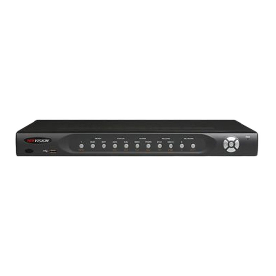
Chapter3 Operational Instructions 3.1 Front panel introduce Fig 3-1 Front panel introduce Form 3-1 Items on front panel Index Type Name Description Lamp IR receiver. USB interface Numeric Input number, lower case, upper case character and Keys symbols. MENU 1. Switch preview mode into menu; 2. -
Page 10: Ir Controller
In preview mode, display or hide the channel status bar. SHIFT Switch between numeric keys and function keys State READY DVR is ready. Lamps STATUS Green means you can use IR remote control. ALARM Red means there is alarm. RECORD Twinkle in red means reading or writing HDD. - Page 11 Form 3-2 Instruction of IR Index Name Description POWER Turnoff device. Enable/Disable IR remote control Numeric Keys Same as numeric keys of front panel. EDIT Same as EDIT key of front panel. Same as A key of front panel. Same as REC key of front panel. PLAY Same as PLAY key of front panel.
- Page 12 panel is turned into green, it means you can use IR controller to operate this DVR. Stop using IR controller When IR controller status is on, press 【 DEV】 key again, the “STATUS” lamp will be turned off. The IR controller can not control this DVR. Switch the DVR off When IR controller status is on, press【POWER】key for several seconds, the DVR will be powered off.
-
Page 13: Menu Description
Menu Description 3.3.1 Menu Items Form 3-3 First Glance at menu Menu Name Function Menu Name Function Unit name Select camera Device ID Camera name Require password Color setup Screen saver Date OSD position Video standard View tampering area and response Enable scaler setup Display... -
Page 14: Menu Operation
User rights setup HDD management Stop alarm output Reboot View log System information 3.3.2 Menu Operation How to enter into menu mode Press【MENU】key to enter into DVR main menu. Press【PLAY】short key to enter into playback menu. Press【REC】short key to enter into manual record menu. Press【PTZ】short key to enter into PTZ control interface. - Page 15 using direction keys (【↑】 【↓】). When the “Active Frame” is located on one icon, you can press 【ENTER】key to enter into the sub menu. For example, move the “Active Frame” to “Image” icon, press 【ENTER】to enter into the sub menu as following fig 3.4: Fig 3.4 Camera input adjustment Each menu contains different kinds of items.
- Page 16 press “Policy” button to enter into sub-menu. Press【Confirm】to save parameters and return to parent menu. Press【Cancel】button to cancel and return to parent menu. The button in grey means it can be operated only after it is enabled. How to exit menu Press【PREV】key to exit menu and return to preview mode.
-
Page 17: Input Text
3.4 Input text In the menu interface, if you are in edit status (for example, in the “camera name” edit box), at the bottom of screen, the input status is appeared: Here it means you can press numeric keys to input digital number. Press【A】key to change input methods. -
Page 18: Chapter4 Basic Operation Guide
Chapter4 Basic Operation Guide Power on Note: Please make sure the power supply matches DVR and AC adapter connected correctly. Before switch DVR on, please connect one monitor with VOUT or VGA interface. Otherwise, you can not see graphic user interface and can not operate. - Page 19 Fig 4.1 Recording status Form 4-1 Camera record status Icon Icon Color Status Description White No video signal Yellow Video input Pink Manual recording Green Real time recording Blue Motion detect recording External alarm recording...
- Page 20 Fig 4.2 Alarm status Camera alarm status is following: Form 4.2 Camera alarm status Icon Icon Color Status Description White Video signal lost Yellow View tampering alarm Pink Motion & External alarm Green No alarm Blue Motion alarm External alarm Press numeric keys to switch over individual camera preview.
-
Page 21: User Name And Password
User name and password Note: When DVR is delivered from factory, there is only one default administrator named “admin”, and password is “12345”. The administrator’s name can not be modified, while the password can be modified. The administrator can create 15 users and define their user rights. Login Login dialog is following Fig 4.3 Fig 4.3 Login dialog... - Page 22 Fig 4.5 Main menu Step 2: Select the objective user name by using 【↑】,【↓】 then move the “Active Frame” to “Password” icon by using【 】/【 】keys. As fig 4.6 shows.
-
Page 23: Ptz Control
Fig 4.6 Modify users’ password Step 3: Input new password Use numeric keys to input new password. The password can be null. It also can be 16 numerals. Press【ENTER】to exit edit box, and move to “Verify” item to verify password. Note: In edit box, use 【... -
Page 24: Select Channel
Fig 4.7 PTZ Control interface Currently controlled camera’s name is displayed which the position is defined by yourself. Select channel In PTZ control mode, you can press numeric keys to select channel. For example, press【2】key to select the second camera PTZ. After you select the camera PTZ, you can use the control keys to control PTZ. - Page 25 Adjust preset description In PTZ control mode, press 【 REC/SHOT】 key, and press the preset number (three numeric keys), DVR will adjust the corresponding preset number. Repeat pressing 【REC/SHOT】key, and press the preset number, DVR will adjust that preset number. When you exit PTZ control mode, the camera will stay at the current position.
-
Page 26: Manual Record
Manual Record Note: The user must have the corresponding right, DVR has HDD and HDD is formatted already. Manual record In preview mode, press【REC】key, in the pop-up login dialog, select the name and input the correct password, you can enter into the “Manual Record” interface. In menu mode, press 【... -
Page 27: Playback
Start All: Press this button to start all channels recording. Stop All: Press this button to stop all channel recording. Press【ESC】key to enter into preview mode. Press【MENU】key to enter into main menu. Press 【PLAY】 key to enter into playback menu. Press 【PTZ】 key to enter into PTZ control mode. - Page 28 Rec Type: Use【↑】or【↓】to select recorded files type. The file type options have “All”, “All Time”, “Motion Detect”, “Alarm” and “Manual”. Time Section: You can define the search time section. Move “Active Frame” to the time edit box, use numeric keys to input the detail time. Search: Search the matched recorded files and display them in the list box.
- Page 29 Display/Hide information bar: 【MENU】 Open/Close sound: 【PLAY】 Adjust play progress: 【←】(Backward),【→】(Forward). The unit is “%”. Adjust play speed: Normal speed is “1x”. Use 【↑】to increase play speed ( 2X, 4X, 8X and MAX). Use【↓】to decrease play speed (1/2X, 1/4X, 1/8X and single) Pause/Continue: Press 【ENTER】...
- Page 30 Control bar descriptions: : You can click these buttons to skip backward or forward 3% each time. : You can click these buttons to select the play speed : Click this button to pause. : Click this button to be mute, click it again to recover the sound.
-
Page 31: Backup Recorded Files
Backup Recorded Files Note: The user must have “Playback” right. Please connect with backup devices before you start to backup. In the playback interface, you can backup the recorded files. In the preview mode, press 【PLAY】 key, in the login dialog, select username and input the correct password, you can enter into the playback interface. - Page 32 Fig 4.12 Playback list Step 3: Select backup device Please confirm the backup device: USB flash memory, USB HDD, USB CD-R/W, and select the corresponding backup device. Step 4: Start and finish backup Move “Active Frame” to “Save” button and press【ENTER】key to start backup. When backup is started, corresponding message box will pop-up to indicate the result.
-
Page 33: Shut Down Dvr
Shut Down DVR Note: Do not switch off the power directly in case of damaging HDD. The correct step is using “Power Off” in the “Utilities” menu, or【POWER】key on the front panel or on IR controller. Shut down DVR normally Use menu Enter into “Utilities”... -
Page 34: Chapter5 Parameters Setup Guide
Chapter5 Parameters Setup Guide Only the users that have “Parameters Setup” right need to read this chapter. When the following parameters are modified and saved, you must reboot the DVR to make the new parameters take into effective. Other parameters do not need to reboot. Any network parameters resolution and record schedule External alarm sensor type... - Page 35 Fig 5.1 Enter into user menu Move “Active Frame” to “User” icon, press【ENTER】key to enter into “User Management” menu. Shown as fig 5.2...
- Page 36 Fig 5.2 User management In the user name list box, only “admin” is existed. You can use【→】key, move “Active Frame” to password edit box, and press【EDIT】key to enter into edit status. Press numeric keys to input the new password. The password is only combined by 16 numerals at most.
-
Page 37: Add And Delete User
Add and Delete User Enter into “User Management” interface. Add user The steps are following: Step 1: Enter into “User Management” menu as fig 5.4 Please refer to chapter 5.1 Fig 5.4 user management Step 2: Add new user name In the “User Management”... - Page 38 Fig 5.5 Input user name Step 3: Setup the password for new user After you add one new user, the password is null. You can skip this step if you do not want to change the password. In the users list box of “User Management” menu, use 【 】 【 】 keys to select the new user name, then use 【...
- Page 39 Fig 5.6 Set user right Operational rights are divided into “Local” and “Remote”. You can assign the necessary rights to the user. Use【 】 【 】key to move “Active Frame” to the corresponding right items, press 【 ENTER】 or 【EDIT】 key to enable or disable the item. “...
- Page 40 PTZ Control: Remote control PTZ; Record: Remote manual start/stop recording; Set parameters Setup: Remote setup the DVR parameters; Log: Remote view the log on DVR; Utilities: Remote upgrade firmware, format HDD, reboot DVR and shut down DVR, etc. Talk: Client talks with DVR; Alarm: Remote control DVR alarm output;...
-
Page 41: Unit Name And Device Id
Unit Name and Device ID Unit name In the “Display” menu, shown as fig 5.8: Fig 5.8 Display menu There is an item named “Unit Name”. The default unit name is “Embedded Net DVR”. Move “Active Frame” to unit name edit box, press【EDIT】key to enter into edit status, you can modify the unit name. - Page 42 or press “Cancel” to abort modification.
-
Page 43: Video Output Standard And Vga Setup
Video Output Standard and VGA Setup Video output standard There is one VOUT BNC connector at the rear panel of DVR. It is used to connect with analog monitor and can support PAL or NTSC video output. You can modify video output standard to match video input. In “Display”... -
Page 44: Camera Name And Osd Setup
5.5 Camera name and OSD Setup Camera Name In “Camera” menu, you can define name for each camera. Please notice that camera’s name can not be copied. Shown as fig 5.9 Fig 5.9 Input camera number The steps of camera name setup: Step 1: Select one camera. - Page 45 “Active Frame” to “Position” button, press【ENTER】to enter into camera name position setup interface, as picture below in that interface, you can use 【 】 【 】 【 】 【 】keys to move camera name position. When the position is fixed, press 【ENTER】and return “Camera”...
- Page 46 In “Camera” menu you can adjust the position where you want Date to display, move active frame to “Position” item on the right side of “Date OSD” item and press enter button. Then you will see the picture below. Use 【↑】 【↓】 【←】 【→】 to adjust the position of date.
-
Page 47: Video Parameters Setup
Video Parameters Setup For different camera and different background, in order to get the best video image, you need to adjust video parameters such as brightness, saturation, contrast and hue, etc. You can setup the camera individually, and also you can copy the video parameters of one camera to any other cameras. - Page 48 After adjusting, in “Image Setup” menu, press “Confirm” button to save parameters and make them into effective. Otherwise, press “Cancel” button or【ESC】 key to abort modification.
-
Page 49: Mask Area Setup
Mask Area Setup In some cases, maybe you want mask the sensitive area. This area will not be preview and recorded. The mask area setup steps are following: Step 1: Enter into “Camera” menu: Step 2: Select one camera: You can use【 】 【 】keys to select one camera. Step 3:Enter into “Advanced settings”... - Page 50 Here is the example for mask area function. Shown as fig 5.14 Fig 5.14 Area masked Disable the mask check box means cancel the mask area.
-
Page 51: View Tampering Alarm
View Tampering Alarm If you enable this function, when someone blocks the camera spitefully, DVR will make warning alarm. Step 1: Enter into “Camera” menu: Step 2: Select camera: Please use【 】 【 】keys to select one camera. Step 3: Select sensitivity: move active frame to sensitivity item right beside the “View tampering”... - Page 52 Step 6: Alarm schedule setup: When there is view tampering alarm happened, DVR will handle the alarm based on the schedule. You can set 4 periods for each day one week. Also you can copy the schedule of one day to other days. Notes: Time periods can not be repeated.
-
Page 53: Video Loss Alarm
Video Loss Alarm When the video cable or camera has something wrong, the video image is lost. If you enable video loss alarm, in such case, DVR will make alarm. Step 1: Enter into “Camera” menu: Step 2: Select camera: Use【 】 【 】keys to select one camera. Step 3: Enter into “Advanced settings”... - Page 54 menu. Step 7: Save all cameras: If you want to setup other cameras, please repeat from step2 to step 6. In “Camera” menu, press “Confirm” key to save all cameras parameters. Press “Cancel” button or【ESC】key to abort.
-
Page 55: Motion Detection
5.10 Motion Detection If you enable this function, when there is motion detected, DVR will make alarm. Step 1: Enter into “Camera” menu: Step 2: Select camera: Use【 】 【 】key to select one camera after pressing 【edit】key. Step 3: Select motion detection sensitivity: On the right side of “Motion Det. Level” item, there is a list box. - Page 56 press【EDIT】, you will find the yellow pane is turned into black pane. You can use【↓】 【→】 key to enlarge or shrink the blue area. Press【EDIT】key to clear this part motion area. Press【Enter】key to save and return “Image” menu. Press【ESC】to cancel. Clear all motion areas: Press【A】key to clear all motion areas of this channel.
-
Page 57: Preview Properties
Note: In order to make the cameras start recording, in “Recording” menu, you must enable recording schedule and set “Rec Type” as “Motion Detection” or “Motion | Alarm”. Please refer to chapter 5.12 for recording setup. Step 7: Motion alarm schedule: When the motion alarm is happened in schedule, DVR will response such as “On Screen Warning”, “Audible Warning”, “Upload to Center”... - Page 58 Fig 5.19 Setup preview mode Step 2: Preview properties: Preview mode: For preview mode item, you can use【↑】 【↓】key to select one mode. If DVR has only 1 channel, you can select only “1 Screen” option. If DVR has 4 channels, there are “1 Screen”...
- Page 59 display order. If you press 0, then the corresponding window will not display live video. After you define the camera preview order, you can select preview mode to meet your demand. Save setup: Press “Confirm” button to save preview properties. Press “Cancel” or 【ESC】 key to abort.
-
Page 60: Recording Setup
5.12 Recording Setup In main menu, there is an icon named “Recording”. You can enter into recording menu as following: Fig 5.20 Recording channel configuration “Recording” menu description: If HDD Full: There are two options: “Overwrite” and “Stop recording”. If you select “Overwrite”... - Page 61 Note: If you change this resolution option, please reboot DVR to make it into effective. Bit Rate Type: DVR will use the fixed bit rate to compress image. The bit rate size is defined in “Bit Rate” option. In this case, we can calculate the recorded file size and network bandwidth that we need. The max bit rate selection has relations to resolution.
- Page 62 For “Rec Type” item, the options are: All Time, Motion Detect, Alarm, Motion|Alarm, and Motion&Alarm, command. For all day record mode, only one record type can be selected. Step 4: Copy to other days You can repeat step2 and step3 to setup for other days. Also you can copy the current day to other days.
-
Page 63: External Alarm Input And Relay Output
5.13 External Alarm Input and Relay Output For DS-7108 , there are 16 alarm in and 4 relay out. In “Alarms” menu, you can setup for each external alarm input. In main menu, move “Active Frame” to “Alarms” icon and press【ENTER】key to enter into alarms menu: Shown as fig 5.22 5.22 Alarms setup External alarm input setup:... - Page 64 Fig 5.23 Alarm in handling setup Step 4: Alarm trigger record channel setup You can select channels to record for each alarm input. In the sub menu, you can use 【ENTER】or【EDIT】key to enable record channel. “×” means disable and “ means enable. Note: In order to trigger the channel to record, in “Recording”...
- Page 65 Step 8: PTZ Linkage Move “Active Frame” to “PTZ Linkage” button, press【ENTER】key to enter into “PTZ Linkage” setup menu: Shown as fig 5.24 Fig 5.24 PTZ linkage setup First select one camera, then select one of following PTZ linkage: Preset: Set the flag as “ ” to enable preset, in the preset number edit box and input one preset number that has been setup already.
- Page 66 Step 2: Select delay time The delay time is when the alarm is disappeared, the alarm output will continue output time. The delay time options are: 5 Seconds, 10 Seconds, 30 Seconds, 1 Minute, 2 Minutes, 5 Minutes, 10 Minutes and Manual Stop. If you select “Manual’ option, the alarm output will not stop until you press “Clear Alarm”...
- Page 67 Exceptions The exceptions can be handled at present include: hard disk full, hard disk error, illegal access, IP address conflict, network failure, and NTSC/PAL differ. Enter into “Exceptions” menu: Shown as fig 5.26 Fig 5.26 Exceptions setup Including the following handle methods: Audible Warning: DVR beep warning.
-
Page 68: Network Parameters
5.14 Network Parameters If you want use network to access DVR, you must setup network parameters. Note: If any network parameter is modified, you must save and reboot DVR to make it into effective. In main menu, move “Active Frame” to “Network” icon and press【ENTER】, you can enter into “Network”... - Page 69 Remote Host IP and Port: If you set this IP and port, when there is alarm and exception happened, DVR will send information to that host IP. The center with this IP can receive alarm and exception information from DVR. You can use SDK to develop this center software. HttpPort: The port is for IE browser.
-
Page 70: Ptz
not use multicast function, you do not need to set. Some routers will prohibit multicast function in case of network storm. PPPoE: DVR support PPPoE dail-up function. Example: Use PPPoE function Step 1: Enter into “Network” menu. Step 2: Select NIC type. Step 3: Input port number. - Page 71 Fig 5.29 PTZ parameters setup PTZ menu description Select channel: Select one PTZ camera. RS-485 parameters: Including baud rate, data bit, stop bit, parity, flow control, etc. These parameters must be the same as those of PTZ. Protocol. PTZ address: Each PTZ has one different address. PTZ type: DVR had the following PTZ protocol: YouLi, LinLin-1016, LinLin-820, Pelco-p, DM DynaColor, HD600, JC-4116, Pelco-d WX, Pelco-D, VCOM VC-2000, NetStreamer, SAE/YAAN, Samsung, Kalatel-312, CELOTEX, TLPelco-p, TLHHX-2000, BBV, RM110,...
- Page 72 support preset function before you setup preset. Sequence setup: Each sequence is made up of several cruise points. Each cruise point includes one preset number, dwell time and dwell speed. Please make sure the PTZ you are using can support sequence function before you start to setup. You can save 16 sequences. Cruise setup: Cruise is remembering the track of PTZ movement.
- Page 73 button, you can delete this preset number. After deleting, press “Return” button to “PTZ” menu. In “PTZ” menu, press “Confirm” button to save all modification. Please make sure the PTZ you are using can support preset function. Sequence setup In “PTZ” menu, press “Setup” button on the right side of “Sequence No” item, you can enter into “Sequence”...
-
Page 74: Rs232 Setup
Please make sure the PTZ you are using can support sequence function. Cruise setup In “PTZ” menu, press “Setup” button on the right side of “Cruise” item, you can enter into “Cruise” setup menu: Shown as fig 5.32 Fig 5.32 Cruise setup Press “RecCru”... - Page 75 RS232 menu description RS-232 parameters: Including baud rate, data bit, stop bit, parity, flow control, etc. Work mode: The RS-232 can be used as “Console”, “PPP” or “Transparent Channel”. Console: Connect with PC serial port. You can use HyperTerminal or NetTerm to control it. PPP: Connect Modem, using PSTN to transfer video image.
- Page 76 number of remote PC. Callback and Data Encryption: Only used when work mode is “PPP”. They are not available. Confirm: Save parameters and return main menu. Cancel: Abort modification and return main menu. Example: PPP (Modem) passive dialup through PSTN There are two Modems.
- Page 77 Step 3: Save setup In “Recording” menu, press “Confirm” button to save parameters. Step 4: Setup Modem used on DVR side Use DCE calbe to connect Modem with PC serial port. You can use HyperTerminal or NetTerm to setup modem: AT&F ---- Retore default parameters (Generally, Modem is hard flow control) AT&S0=1 ---- Set Modem as answer...
- Page 79 Step 3: Establish the dialup connection Select the Modem connected with PC just like the dialup network connection, input the telephone number connected with DVR’s modem. Input the username, password. They must be the same as that DVR PPP setup. Step 4: During the dialup connection, it will give the message of “verification of username and password”, after successfully verification;...
-
Page 80: Chapter6 Utilities
Chapter6 Utilities There are many tools in “Utilities” menu. Including “SavePara”, “RestorePara”, “Upgrade”, “Hard Disk”, “Stop Alarm Out”, “Reboot”, “Power Off”, “View Log” and “System Info”. Enter into “Utilities” menu: Shown as fig 6.1 Fig 6.1 Utilities Restore Parameters Restore factory parameters for DVR. The IP address, gateway and port number will not be restored. -
Page 81: Upgrade
Fig 6.2 Restore parameters Upgrade You can use this function to upgrade the firmware. Please confirm the language is matched. Press “Upgrade” icon, in the pop-up dialog, you can select either “FTP” or “USB” upgrade mode. Shown as fig 6.3 Fig 6.3 Upgrade If you select “FTP”... -
Page 82: Hard Disk Management
If you select “USB” mode, please make sure you connect one USB flash memory with DVR and the firmware file is in it’s root directory. Reboot after successfully upgrading, the system will use the new firmware. Hard Disk Management fig 6.5 Hard Disk setup Check HDD work status Capacity, Free space, Stand by or not, Normal status or not. -
Page 83: Reboot
Reboot Reboot DVR. Power Off Shut down DVR. View Log To view the log recorded in DVR HDD. In “Utilities” menu, press “View Log” to enter into “Log” menu: Shown as fig 6.6 Fig 6.6 View log If you want to view the log based on default option, just press【ENTER】key. DVR will list all matched information. - Page 84 For operation major type, there are many minor types, including Power On, Shut Down, Abnormal Shut, Panel Login, Panel Logout, Panel Config, Panel File Play, Panel Time Play, Local Start Record, Local Stop Record, Panel PTZ, Panel Preview, Panel Set Time, Local Upgrade, Net Login, Net Logout, Net Start Record, Net Stop Record, Net Start Transparent Channel, Net Stop Transparent Channel, Net Get Parameter, Net Config, Net get Status, Net Alert On, Net Alert Off, Net Reboot, BiComStart (Start Voice Talk), BiComStop (Stop Voice Talk), Net Upgrade, Net File...
- Page 85 By Type&Date View one kind of log in the assigned time period. Step 1: Select “By Type&Time” for “Query” option to active “Major Type”, “Minor Type” “Start Time” and “Stop Time” items. Step 2: Select “Operation” for major type and select one option for minor type. Step 3: Input start time and stop time.
-
Page 86: System Information
System Information Press “System Info” icon in “Utilities” menu, you can get DVR system information: Shown as fig 6.7 Fig 6.7 System information... -
Page 87: Chapter7 Firmware Upgrade
Chapter7 Firmware Upgrade The DVR firmware is stored in FLASH ROM. You can use DVR upgrade function to write the firmware file (digicap) into FLASH. There are two cases that you need to upgrade DVR firmware. One is update old firmware. The other is when the code in DVR FLASH is crashed. - Page 88 Fig 7.2 setup parameters Select “Users/rights” under “Security” menu item. The following dialog box will be pop-up. Fig 7.3 Setup username Create new user. Click “new user’. New user dialog pops up. Input user name “target”. Click “OK”. Fig 7.4 username In the password dialog, input password “target”...
-
Page 89: Upgrade Mode
Fig 7.9 Setup home directory 7. Next time, you need not setup again, just double click and open “wftpd32.exe” to upgrade the DVR/DVS firmware. 7.2 Upgrade Mode Use client software to upgrade the firmware file. You do not need to use ftp server software. - Page 90 Fig1...
- Page 91 Fig 2 2) Input the name “hikvision”. And do the step 1 again. Then enter into fig 4. select COM1 and click “OK” to enter into fig 5. Fig3 Fig 4 3) Modify the bits per second to ‘115200’. and modify the flow control to’ None.’ Finally...
- Page 92 Fig 5 Step 2: Then reboot the device and press any button in the pc keyboard again and again until the HIK # come out in the Hyper Terminal interface, show as fig 6. then input the “print” to check if the IP of the server and device is correct, also both of them should be in the same LAN.
- Page 93 Fig 6 Fig 7 Step 3:...
- Page 94 Input the commend “save” and press enter button. Show as fig 8. Fig 8 Step 4: Input the commend “update” and press enter button, then space button. After that the update will start. Show as fig 9...
- Page 95 fig 9 Step 5: After the update finished, please input the command “reset” and press the enter button. The device will reset. Show as fig 10.
- Page 96 Fig 10...
-
Page 97: Appendix A Mouse Control Function
Appendix A Mouse control function 1. in the preview interface Double-click the left key 1. Switch to the most pictures when viewing single picture. 2. Switch to full screen mode when viewing multi-pictures. Back to previous multi-pictures when double click again Scroll wheel forward Switch to previous screen Scroll wheel backward... -
Page 98: Appendix Bhdd Capacity Calculation
5. Test input interface Click the left key 1. pop up soft keyboard 2. Input text 3. Save and exit Click the right key Cancel the text and exit the edition Scroll wheel forward Cursor go to the front character 6. - Page 99 channel needed for every hour, unit Mbyte. ÷ × ÷ 3600 1024 In the formula: means the bit rate, unit Kbit/s Step 2: After video time requirement is confirmed, according to Formula (2) to calculate the storage capacity , which is storage of each channel needed unit Mbyte. ×...
-
Page 100: Appendix Cdvr Connect Cable Definition
Appendix C DVR Connect Cable Definition 1 RS-485 connect cable made method Material and tool One twist cable (8 pins), one standard RJ45 connector and one tool special for RJ45. RJ45 introduction Pin definition To make the connect cable according the follows. As to left point of RJ45 head, 1 and 2 cables are the anode and cathode line for sending, 3 and 4... -
Page 101: Utp Network Connect Cable Made Method
Ground Request to Send Clear Data 3 UTP network connect cable made method Material and tool One twist cable (8 pin, the length can be defined as to the actual demand, but must be within 100m), 2 standard RJ45 head, one tool for RJ45. Suggestion: have a network cable test tool to test each cable made. - Page 102 The corresponding relationship of cross cable...
-
Page 103: Appendix D Specifications
Appendix D Specifications Model DS-7108HI Compression standard H.264 Preview resolution PAL:704*576(4CIF) NTSC704*480(4CIF) Recording resolution PAL:352*288(CIF) NTSC352*288(CIF) Video input 8 channels BNC ( 1.0 Vp-p ,75 Ohm) Video out 1 channel BNC (1.0Vp-p ,75 Ohm) Video spot 1 channel BNC (1.0Vp-p , 75 Ohm) Frame rate PAL: 15FPS, NTSC: 20FPS Audio compression standard... -
Page 104: Appendix E Troubleshooting
Appendix E Troubleshooting Failure Possible reasons After plugging in power, turning on the power switch, Power cable is broken. “POWER” light in front Panel does not turn on, and fan Power supply is broken. does not work. After plugging in power, turning on the power switch, Front panel cable is broken. - Page 105 If the circuit board is wet, dust on circuit board can cause a short circuit. The circuit board, plug and socket, housing fan and housing should be cleaned by brushing regularly.
-
Page 106: Appendix F Product Service
Appendix F Product Service Thank you for choosing our products. All of our products users can enjoy a conditional free repair guarantee service for hardware within 12 months starting from purchase date, and a free exchange service within one month (valid for the damage caused by non personal acts). -
Page 107: Appendix G Customer Information Card
Appendix G Customer Information Card User’s Name Mr./Mrs. Company Name Post Address Postcode Phone Number E-mail Model Number Product Serial Number Product Purchase Date Distributor... - Page 108 Suggestions:...
Need help?
Do you have a question about the DS-7108HI series and is the answer not in the manual?
Questions and answers