Olivetti ECR 7900 Service Manual
Hide thumbs
Also See for ECR 7900:
- Bruksanvisning (62 pages) ,
- User manual (62 pages) ,
- Installation and reference manual (22 pages)
Table of Contents
Advertisement
Quick Links
Advertisement
Table of Contents
Troubleshooting

Related Manuals for Olivetti ECR 7900


Summary of Contents for Olivetti ECR 7900
- Page 1 Cash Register ECR 7900 SERVICE MANUAL Code Y108540-8...
- Page 2 PUBLICATION ISSUED BY: Olivetti S.p.A. 10015 Ivrea (Italy) Gruppo Telecom Italia Via Jervis, 77- 10015 Ivrea (ITALY) www.olivetti.com Copyright© 2008, Olive All rights reserved ATTENZIONE Pericolo di esplosione se la batteria non viene sostituita in modo corretto. Sostituire solo con un tipo uguale o equivalente raccomandato dal costruttore.
-
Page 3: Table Of Contents
CONTENTS MAJOR FEATURES....................1 ECR 7900 CASH REGISTER COMPONENTS ............2 CASH REGISTER SPECIFICATIONS ............... 3 SAFETY PRECAUTIONS ......................4 MAINTAINING THE CASH REGISTER ................... 4 UNPACKING AND SETTING UP THE CASH REGISTER......... 5 STANDARD ACCESSORIES ....................5 THE KEYPAD FOR ECR 7900................... 6 KEYPAD FUNCTIONS...................... - Page 4 5-1.USB driver install ......................66 6. ASSEMBLY INSTRUCTION................. 73 6-1. TOP CASE UNIT ......................73 6-2. Display unit ASSY ......................80 6-3. Bottom case unit ASSY ....................83 8. CIRCUIT DIAGRAM ..................... 93 9. EXPLODED DIAGRAM..................101 ECR 7900 Service Manual Y108540-8...
- Page 5 Chapter 5 describes the electronic circuitry. PREREQUISITES The topics described in this manual require knowledge of similar products. REFERENCE DOCUMENTATION • Instruction Manual (provided with the product) • Spare Parts Catalogue DISTRIBUTION: General LAST EDITION: January 2008 Y108540-8 ECR 7900 Service Manual...
-
Page 7: Major Features
User-defined captions in any language for printing on receipts and reports; Keypad personalization through reassignment of keys; • Programmable key sequences executed by actioning single chain function keys; • Sales function selection via pop-up Iists; • Barcode reader connectivity. Y108540-8 ECR 7900 Service Manual... -
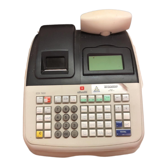
Page 8: Ecr 7900 Cash Register Components
ECR 7900 CASH REGISTER COMPONENTS With reference to figure: 1. Customer display. 2. Operator display. 3. Keypad. 4. Cash drawer and box. 5. Cash drawer lock and slot. 6. Item deposit drawer. 7. Power cord. 8. Storage Device (SD) - under printer compartment cover. -
Page 9: Cash Register Specifications
Technology: CMOS RAM. Powercons. Standby 12.1 W, Operating4l.8W. Operating 32 — 104°F (0°C —40 °C) Temperature: Dimensions: 10 mm (W) x 430 mm (D) x 294 mm (H) Weight: 9,9 Kg (21,82 lbs) Y108540-8 ECR 7900 Service Manual... -
Page 10: Safety Precautions
DO NOT attempt to pull the paper tape when the cash register Is printing or when you are loading paper. Always use the [Feed] key to feed paper. Pulling the paper tape could damage the print mechanism. ECR 7900 Service Manual Y108540-8... -
Page 11: Unpacking And Setting Up The Cash Register
WARNING: The machine must be plugged into an electrical outlet before you insert the batteries. 4. Load the thermal paper roll as explained in the section entitled Loading Thermal Paper. 5. Set the desired program options as explained in the section Cash Register Programming. Y108540-8 ECR 7900 Service Manual... -
Page 12: The Keypad For Ecr 7900
THE KEYPAD FOR ECR 7900 The figure below shows the keypad layout KEYPAD FUNCTIONS The keys described here are those configured by default on the cash register keyboard, shown in figure 5. The symbol (*) indicates that the key is also used in caption programming. - Page 13 Electronic Journal status and number of free EJ lines. Using the LCD contrast can be adjusted. When operated during a sales transaction, allows multiple quantities to be specified for a sales item. Y108540-8 ECR 7900 Service Manual...
- Page 14 24. - In Programming mode, when selecting data for preset value fields, use these keys to scroll through the values available, highlight the value wanted, and then select with ECR 7900 Service Manual Y108540-8...
-
Page 15: Operator And Customer Displays
(3) n/a Receipts 0ff - no receipts are issued until is pressed again. (3) n/a EJ nearly – full condition (Clerk ld.) n/a If the Clerk System is active, the clerk number/name is displayed after logon at top left. Y108540-8 ECR 7900 Service Manual... - Page 16 8-digits (rightside (no.) CD). lndicates that a Take-out tax rate is applied to the transaction. n/a = not applicable. These symbols clear automatically when you start the next entry or press the key. ECR 7900 Service Manual Y108540-8...
-
Page 17: Programming Mode - Operator Display
Ref. (1) Data Entry Mode – Uppercase letters Ref. (2) In Navigation Mode, field selection Ref. (5) In Navigation Mode, indicates a menu option (appears on the right) Ref. (2) Manager mode PROGRAMMING MODE – Operator Display Y108540-8 ECR 7900 Service Manual... -
Page 18: Printer Compartment
3. Release and Iift the clamshell mechanism as shown in the following figure. 4. With a pair of scissors, cut the end of the paper tape to create a straight, even edge so that the paper can be properly fed through the print mechanism. ECR 7900 Service Manual Y108540-8... - Page 19 8. Pass the edge of the customer receipt through the receipt window on the compartment cover. 9. Insert the edge of the paper into the paper slot as shown below. Reposition and dose the printer compartment cover. Y108540-8 ECR 7900 Service Manual...
- Page 20 ECR 7900 Service Manual Y108540-8...
-
Page 21: Product Outline
Rear display is 10-digits 16 segment VFD. <Front Display> <Rear Display> 10 digit VFD 160 x 80 dot matrix 1 x Alphanumeric MultiLine LCD 14mm C.H. x 4.9mm Adjustable Display Angle, LCD Housing View area : 89.0mm x 47.5 Y108540-8 ECR 7900 Service Manual... -
Page 22: Keyboard
1-3. KEYBOARD The keyboard consists of Stroke 42 keys with key caps (except numeric keys). Department keys and letters for Numeric keys Amount tender key programming ECR 7900 Service Manual Y108540-8... -
Page 23: Drawer
1-4. DRAWER The drawer type is DSCA, 4 Bill / 8 Coin with D/DRAWER. D/Drawer 4 Bill tray 8Coin tray Y108540-8 ECR 7900 Service Manual... -
Page 24: Printer
The printer is SII LTPC-235, that is a line thermal printer developed for ECR use. 58mm 1 Station Thermal Printer. 1-6. INTERFACE RS232C for Barcode Reader, USB for PC communication and SD memory card slot. USB I/F for PC RS232C for Barcode Reader SD Memory card slot ECR 7900 Service Manual Y108540-8... -
Page 25: System Block Diagram
Sub Clock A0-A19 D0-D7 FROM RS232C RS232C CS WE OE Driver Interface A0-A18 D0-D7 Interface S-RAM CS WE OE SD CARD Interface +VCC5 +VCC3 +VPRN +VBB Reset +VDRW Power Fail -VPW Power supply Dry Battery Y108540-8 ECR 7900 Service Manual... -
Page 26: Trouble Shooting Guidance
Scanner head lamp lights up but can’t read a barcode. P.33 Cannot use USB I/F Cannot work the USB port. P.33 Cannot use SD card Cannot write or read the data for SD card. P.33 ECR 7900 Service Manual Y108540-8... -
Page 27: Circuitry
R181, R182, a 470 ohm resistor. Fuse for Secondary side. F1 250V 1.6A TR-5 19370 1.6A F2 250V 3.15A MRT3.15A F3 250V 1.6A TR-5 19370 1.6A F4 250V 1A TR-5 19370 1A F5 250V 500mA TR-5 19370 0.5A Y108540-8 ECR 7900 Service Manual... -
Page 28: Trouble Shooting
If it does not output properly- - - Check FUSE F4 continuity and replace it if OPEN. - STEP 2 After replacing FUSE at STEP 1 but the FUSE opens again.- - - Replace Main board. No voltage at all the points from (1) to (7). - - - Replace Transformer. ECR 7900 Service Manual Y108540-8... -
Page 29: Transformer Wiring Diagram
After replacing FUSE but it opens again.- - - Check Power Supply circuit. (P.9, 10) - Check the Thermal Fuse. Check the voltage (AC 4.8V) at point (1) (6 pin and 7 pin). If it outputs almost 0V - - - Replace Transformer. Y108540-8 ECR 7900 Service Manual... -
Page 30: M30842Mc Microcomputer
3-3. M30842MC MICROCOMPUTER Refer to the specification (attached). ECR 7900 Service Manual Y108540-8... - Page 31 ( H ) C PU C ont r ol Si gnal 18 Xcout I / O Xcout C r yst al 32. 768kH z f or R TC 17 Xci n I / O Xci n C r yst al 32. 768kH z Y108540-8 ECR 7900 Service Manual...
- Page 32 Pow er : Pow er suppl y i nput P. U . : Pul l up ( VBB) p. u. : Pul l up ( VC C ) P. D . : Pul l dow n ( G N D ) ECR 7900 Service Manual Y108540-8...
-
Page 33: Reset Circuit
DC +3.3V - - - Reset circuit is OK. The problem may come from other causes. Check the Power supply circuit again and replace Main board if no problem found in the power supply circuit. 0V - - - Reset circuit has a problem. Replace Main board. Y108540-8 ECR 7900 Service Manual... -
Page 34: Power Fail Circuit
From Motor C5 8 1SR154-400 *0.1 uF_5 0V C5 9 C6 0 *0.1 uF_5 0V *0.1 uF_5 0V R1 35 WIND_O N WIND_ON 4.7 K 2SD1817 R8 8 W I ND M OTOR I / F ECR 7900 Service Manual Y108540-8... - Page 35 If it does not output properly - - - Check Power supply circuit (p. 9-11) Check voltage (DC +5.0V) at point (2) If it output properly - - - Replace the motor or Main board If it does not output properly - - - Replace the Main Board Y108540-8 ECR 7900 Service Manual...
-
Page 36: Display Circuit
DC 0V - - - Replace Main board. - No display and no backlight. Check voltage at point (1) DC +5V - - - Replace LCD unit or Main board. DC 0V - - - Check Power supply circuit. (P.9-11) ECR 7900 Service Manual Y108540-8... - Page 37 If it doesn’t output properly - - - Check Power supply circuit. (P.9-11) Check voltage (DC +5V) at point (5) If it outputs properly - - - Replace Customer Display Unit. If it doesn’t output properly - - - Check Power supply circuit. (P.9-11) Y108540-8 ECR 7900 Service Manual...
-
Page 38: Display Information
Part No.: GY1608A8SKY6T Refer to the specification (attached). Rear Display VFD (16 segments) Part No.: 10LY-01G Segment j k b e r p n . (Union Jack) Character size : 14 mm (H) x 4.9 mm (W) ECR 7900 Service Manual Y108540-8... -
Page 39: Keyboard Circuit
- Only a specific key does not work. Check the lead wire. Lead wire is broken - - - Replace Lead wire. Lead wire is not broken - - - Replace K/B unit. When it’s not broken, replace K/B unit. Y108540-8 ECR 7900 Service Manual... -
Page 40: Drawer Circuit
If drawer opens - - - It should not be considered a mechanic problem. Check the voltage at point (1) If drawer does not open - - - It should be considered a mechanic problem. Replace the drawer unit. ECR 7900 Service Manual Y108540-8... -
Page 41: Buzzer Circuit
DTC143EKA Trouble shooting - No buzzer sound when [clear] key is depressed. Check the voltage at point (1) DC +24V - - - Replace Main board. 0V - - - Check Power supply circuit. (P.9-11) Y108540-8 ECR 7900 Service Manual... -
Page 42: Battery Circuit
- Check the voltage at point (1) It outputs almost same voltage as battery voltage - - - Replace Main Board. It outputs much less than the battery voltage or 0V - - - Replace Battery unit. ECR 7900 Service Manual Y108540-8... - Page 43 Y108540-8 ECR 7900 Service Manual...
-
Page 44: External Memory
P52 is used for Output Enable, P50 is used for Write Enable control. EXTERNAL MEMORY CIRCUIT C1 9 A17/CE2 A18/A17 C7 9 RA MCS # *0.0 1uF 0.1 uF BS 62LV4 006S CP-7 0 C7 3 *10 0pF ECR 7900 Service Manual Y108540-8... - Page 45 S-RAM PIN Configuration Refer to the specification. (attached data sheet) Y108540-8 ECR 7900 Service Manual...
-
Page 46: From (S29Al004D70Tfi010)
EXTERNAL MEMORY CIRCUIT D15/A-1 R9 2 FRDY RY /BY C1 7 C1 11 *0.0 1uF 0.1 uF RO M_CS# R9 5 C7 0 RE SET# RESET BY TE *10 0pF S29 AL00 4D70 TFI0 10 ECR 7900 Service Manual Y108540-8... - Page 47 FROM PIN Configuration Refer to the specification. (attached data sheet) Y108540-8 ECR 7900 Service Manual...
- Page 48 ECR 7900 Service Manual Y108540-8...
-
Page 49: Printer Circuit
1, step 2, step 3, step 4 step 1, step 2, ….by inputting the voltage signals in Figure 3-14-1. Figure 3-14-1. Input Voltage Signals for the Sample Drive Circuit Table 3-14-1. Excitation Sequence Y108540-8 ECR 7900 Service Manual... - Page 50 Motor and Thermal Head drive timing Figure 3-14-2. 2-Division Printing Timing Chart ECR 7900 Service Manual Y108540-8...
- Page 51 If DC+5.0V is properly output - - - Replace Main Board. If DC+5.0V is not properly output - - - Replace Printer. - Head-up sensor or Paper-end sensor does not work. - - - Replace Main board and pri nter. Y108540-8 ECR 7900 Service Manual...
-
Page 52: Interface Circuit
VMEM VMEM VSD_EN 0.1 uF R4 1 SD_CS# R4 2 SD_DO R4 3 SD card SD_CK R4 4 SD_DI C3 0 VCC3 *10 pF A2 004W V10-1 0 R4 5 SD_CA RD R4 6 SD_WP ECR 7900 Service Manual Y108540-8... - Page 53 - Cannot write or read the data for SD card Check the voltage (DC +3.0V) at point (2). If it outputs properly - - - Replace Main board or SD card unit. If it doesn’t output properly - - - Replace Main board. Y108540-8 ECR 7900 Service Manual...
-
Page 54: Diagnostic Software
Keyboard unit, Display unit, or Drawer unit etc. Please make sure you should complete the diagnostic software and it means OK when no error occurs through the checkup. DIAGNOSTIC CHECK LIST ECR 7900 Service Manual Y108540-8... - Page 55 Y108540-8 ECR 7900 Service Manual...
- Page 56 ECR 7900 Service Manual Y108540-8...
- Page 57 Y108540-8 ECR 7900 Service Manual...
- Page 58 After repairing the machine, go through the finished goods check list below. It means OK when no error occurs through the checkup. FINISHED GOODS CHECK LIST ECR 7900 Service Manual Y108540-8...
- Page 59 Y108540-8 ECR 7900 Service Manual...
- Page 60 ECR 7900 Service Manual Y108540-8...
- Page 61 Y108540-8 ECR 7900 Service Manual...
-
Page 62: Software Version Check
4-2. SOFTWARE VERSION CHECK Through the diagnostic check, it shows the software version in the beginning of the check. However, it is possible to check only the software version without diagnostic check. SOFTWARE VERSION CHECK ECR 7900 Service Manual Y108540-8... - Page 63 Note) The latest version of the ER7900 is “ Ver 1.01”. Appendix : jig for RS232C PORT Testing jig = Loop back connector for barcode scanner <Connecting Diagram> D-sub 9 pin 1kΩ Y108540-8 ECR 7900 Service Manual...
-
Page 64: Installing Software
USB-COM driver referring to “6 USB driver install”. Please follow the instruction below in numeric order. PC side 1) First of all, please check the PC COM Port number. Right click on [My Computer], and then Click [Properties]. 2) Click [Device Manager]. ECR 7900 Service Manual Y108540-8... - Page 65 Note)If you use usb-com conversion, there might be shown “USB Serial Port (COMn)”. After you checked the COM Port number, please close the “device manager”. 4) Execute Up_Loader. You can find the icon as shown. Y108540-8 ECR 7900 Service Manual...
- Page 66 5) Set the COM Port number using [Com set] button. Set the COM Port number which you checked at 3). Click [OK]. ECR side 6) Unplug the power and remove the battery. 7) Connect the cable to PC. PC side 8) Click [OK]. ECR 7900 Service Manual Y108540-8...
- Page 67 12) If it doesn’t perform properly at this stage, ECR side might have started up the LOADER already. Click [STOP] button first, and then click [ENQ] button to confirm the condition of the ECR. If the LOADER is already started up, go ahead to . Y108540-8 ECR 7900 Service Manual...
- Page 68 PC side 13) When it’s connected to ECR, it shows [Boot OK]. Click [EEPROM Erase] button. 14) When it successfully done the deletion, it shows [OK]. ECR 7900 Service Manual Y108540-8...
- Page 69 15) Click [UP LOAD] button. Select the file you wish to download. Click [Open]. 16) It shows a status for transmitting. Y108540-8 ECR 7900 Service Manual...
- Page 70 17) It shows [Up Load OK] 18) Click [Ver] button. ECR 7900 Service Manual Y108540-8...
- Page 71 ECR will be started-up by the software loaded just now. Now that the machine has installed new software, it is required to check its functions are properly installed or not. Please go back to section 3, “DIAGNOSTIC SOFTWARE” to check the machine. Y108540-8 ECR 7900 Service Manual...
-
Page 72: 5-1.Usb Driver Install
1) Connect the device’s AC plug to the consent. And turn on the power supply of the PC. 2) Connect the USB cable to the PC. Device is detected. 3) Click the “Next”. 3) Click the “Next”. ECR 7900 Service Manual Y108540-8... - Page 73 5) Specify the place of the driver file. Please click ”Next” after checking ”Specify a location”. 6) The folder selection screen is displayed. Click the ”Browse”. 6) The folder selection screen is displayed. Click the ”Browse”. Y108540-8 ECR 7900 Service Manual...
- Page 74 7) Please open the folder that is preserved Win2kcom.inf, and click "Open" after selecting the file. 8) Click the “OK”. 8) Click the “OK”. 9) Click the “Next”. 9) Click the “Next”. ECR 7900 Service Manual Y108540-8...
- Page 75 10) The driver's installation is completed by this operation. Please click "Finish". 11) Next, please confirm whether the driver was normally installed. Please right-click at the My computer, and click “Properties". Y108540-8 ECR 7900 Service Manual...
- Page 76 12) Click the “HardWare tab”. 13) Click the ”Device Manager”. ECR 7900 Service Manual Y108540-8...
- Page 77 14) Please confirm the display of "USB COM test(COMn)". COM7 was made in the example of the following. Y108540-8 ECR 7900 Service Manual...
- Page 78 Please do not turn off the power supply of the device and do not pull out the USB cable while having opened virtual COM port by the application. After that, the port might not be able to be used until the personal computer is rebooted. ECR 7900 Service Manual Y108540-8...
-
Page 79: Assembly Instruction
RUNNER GATE POSITION ON LEFT SIDE KEY TOP SHEET BASE TOP KEY (2) FIX K/B PWB UNIT TO KEY KEY FRAME SCREW FRAME WITH FLAT. IT MUST BE ON FITTING BOSSES POSITION THEN FASTENING 15PCS SCREW. Y108540-8 ECR 7900 Service Manual... - Page 80 2] SLOT MOTOR SET PIECE TO TOP CASE. [AS SHOWN ON THE PAPER ROLLER BELOW PICTURE ] (4) FIX 2PCS BATTERY CONTACT TOP CASE TO TOP CASE. [LOCATION AS SHOWN ON PICTURE.] BATTERY CONTACT [EAM-3363] BATTERY CONTACT [EAM-3362] ECR 7900 Service Manual Y108540-8...
- Page 81 (5) FIX KEY FRAME TO TOP CASE PRESS UNTIL IS LOCKED. (6)FASTENING 6PCS SCREW, TOP CASE KEY FRAME TO TOP CASE. SCREW KEY TOP Y108540-8 ECR 7900 Service Manual...
- Page 82 1]APPEARANCE CHECK LCD COVER COVER. 2] FIX LCD COVER TO TOP CASE. [AS SHOWN ON PICTURE.] TOP CASE (8) FIX LCD COVER TO TOP CASE BY FASTENING 4PCS SCREW. SCREW ECR 7900 Service Manual Y108540-8...
- Page 83 PLATEN ARM THEN FIX TO TOP PLATEN ARM CASE. PLATEN SPRING (10) FIX LCD MODULE UNIT TO LCD MODULE UNIT TOP CASE. NOTE: The display unit is described in the next section (6-2). CABLE SLOT HERE Y108540-8 ECR 7900 Service Manual...
- Page 84 (11) 1] FIX R/DISPLAY UNIT TO TOP R/DISPLAY UNIT CASE. 2] CHECK AND CLEAN REMOTE FILTER AND DISPLAY TUBE BY USE METHANOL. REMOTE FILTER R/DISPLAY CASE. [AS SHOWN ON PICTURE.] REMOTE FILTER AMOU ECR 7900 Service Manual Y108540-8...
- Page 85 1]CLIP FERRITE CLAMP HARNESS ASSY THEN TURN ONE ROUND TO FERRITE 30mm 2] CLIP HARNESS ASSY TO CORD CLAMP. SHOWN FERRITE CLAMP PICTURE.] [1 TURN] CLIP HARNESS ASSY IN THIS CORD CLAMP TOP CASE UNIT Y108540-8 ECR 7900 Service Manual...
-
Page 86: Display Unit Assy
6-2. Display unit ASSY (1) INSERT HARNESS ASSY LCD MODULE UNIT. LCD MIRROR NON-GLARE SURFACE (TAK SILAU) HARNESS ASSY LCD MODULE UNIT SOLDER LED (2) SOLDER HARNESS ASSY TO LCD MODULE UNIT. LCD MODULE UNIT ECR 7900 Service Manual Y108540-8... - Page 87 ASSY TO LCD REAR CASE. 2] FIX LCD MODULE TO LCD REAR CASE. LCD REAR CASE 3] FIX LCD FRONT CASE TO LCD REAR CASE AND PREES UNTIL IS LOCKED. LCD MODULE LCD FRONT CASE Y108540-8 ECR 7900 Service Manual...
- Page 88 (4) CLIP FERRITE CLAMP TO HARNESS ASSY AND TURN ONE ROUND TO FERRITE CLAMP. HARNESS ASSY FERRITE CLAMP [1 TURN] 30mm ECR 7900 Service Manual Y108540-8...
-
Page 89: Bottom Case Unit Assy
6-3. Bottom case unit ASSY 1]APPEARANCE CHECK BOTTOM CASE BOTTOM CASE. 2]STICK CORD CLAMP BOTTOM CASE. [LOCATION AS SHOWN ON PICTURE.] TAB SIDE CORD CLAMP Y108540-8 ECR 7900 Service Manual... - Page 90 1] SLOT HARNESS ASSY TO BOTTOM CASE. [FOLLOW THE HARNESS ASSY SLOT HERE PICTURE SHOWN FIGURE.] TOGETHER HARNESS ASSY WITH BOTTOM CASE BY USE INSULOCK TIE. SHOWN ON PICTURE.] HARNESS ASSY [CA24-903A] BOTTOM CASE INSULOCK TIE 130mm ECR 7900 Service Manual Y108540-8...
- Page 91 (4) FIX TRANSFORMER UNIT TO DRAWER UNIT BY FASTENING 2PCS SCREW. AC CORD SLOT HERE SCREW Y108540-8 ECR 7900 Service Manual...
- Page 92 1] FIX AC CORD TO BOTTOM CASE. AC CORD PUT LIKE THIS 2] FIX INLET SET PIECE TO BOTTOM CASE BY FASTEN 2PCS SCREW. [AS SHOWN ON PICTURE] BOTTOM CASE INLET SET PIECE SCREW ECR 7900 Service Manual Y108540-8...
- Page 93 [AS ON PICTURE 2.] 3] FIX FUSE CAP TO FUSE HOLDER. [AS ON PICTURE 3.] SCREW FUSE PICTURE 2 PICTURE 3 FUSE CAP (7) FASTEN 8PCS SCREW, MAIN PWB TO BOTTOM CASE. MAIN PWB SCREW Y108540-8 ECR 7900 Service Manual...
- Page 94 TO [CN10] INSERT TO [CN8] (9)FIX PRINTER EARTH WIRE AND DRAWER EARTH WIRE TO PLUG HOLE UPPER PLATE THEN COVER FASTENING 1PC SCREW. SCREW EARTH WIRE FROM PRINTE R HEAD EARTH WIRE FROM HARNESS ASSY [CA24-903A] ECR 7900 Service Manual Y108540-8...
- Page 95 PWB. [LOCATION SHOWN ON PICTURE.] FIRST PIN PRINTER PWB JUMPER PRINTER PWB LEAD JUMPER LEAD [13pin] INSERT TO [CN7] [9pin] INSERT TO [CN6] FRONT DISPLAY HARNESS INSERT TO [CN9] BATTERY BOX HARNESS INSERT TO [CN13] Y108540-8 ECR 7900 Service Manual...
- Page 96 MAIN PWB. [LOCATION AS SHOWN ON PICTURE.] LCD MODULE HARNESS INSERT TO [CN11] SD CARD HARNESS INSERT TO [CN2] FIRST PIN K/B JUMPER LEAD INSERT TO [CN1] [10pin] K/B JUMPER LEAD INSERT TO [CN3] [11pin] ECR 7900 Service Manual Y108540-8...
- Page 97 (12) FIX SEMI SET TO BOTTOM CASE SEMI SET (13) FASTEN 2PCS SCREW, TOP CASE TO BOTTOM CASE. SCREW Y108540-8 ECR 7900 Service Manual...
- Page 98 (14) FIX KEY FRAME TO TOP CASE PRESS UNTIL IS LOCKED. DEPOSIT DRAWER (15) COPLETE AND FUNCTION BATTERY TEST. WINDING REEL ASSY UNIT ECR 7900 Service Manual Y108540-8...
-
Page 99: Circuit Diagram
RAMCS# M_ENA ROMCS# SCS# STXD SRXD SCLK SBUSY EPM# *HEADER 2P CON1 *0.1uF_25V CONNECT_PATTERN *10K *74LV1G08 FMP_CNVSS CPU_RST# 9 10 * mark is unmounted parts. *HIF3FC-10PA-2.54DSA C111 0.01uF CPU F-MEM Write Port RESET# RESET# RESET# Y108540-8 ECR 7900 Service Manual... - Page 100 R187 -Vpw BKL_ON BKL_ON DTC143EKA VF1 VF2 10uF_16V Remote Display Interface R116 SBY321611T-320Y-S VFD_CS0# R120 RD_CS# VFD_CS0# VFD_TXD R121 RD_DATA VFD_TXD VFD_CLK R122 RD_CLK VFD_CLK B8B-PH- K-S EC21 SBY321611T-320Y-S 10uF_50V * mark is unmounted parts. ECR 7900 Service Manual Y108540-8...
- Page 101 RS232C #1 TxD1 R159 TxD1 T1IN T1OUT RTS1# R160 RTS1# T2IN T2OUT RxD1 R161 RxD1 R1OUT R1IN CTS1# R162 CTS1# R2OUT R2IN 0.1uF_25V MAX3232CPW R SBY321611T-320Y-S GND-SCREW _HOLE R165 *1M_1/4W * mark is unmounted parts. Y108540-8 ECR 7900 Service Manual...
- Page 102 R178 C102 P_PS P_PS 0.1uF_25V R179 SVCC_ON SVCC_ON WIND MOTOR I/F VPRN R180 33_1W C103 0.1uF_50V B3B-XH R181 4.7k R182 WIND_ON WIND_ON 2SD1817 R183 VPRN VPRN EC18 EC19 10uF_50V 10uF_50V * mark is unmounted parts. ECR 7900 Service Manual Y108540-8...
- Page 103 M51957BFP Power Fail 1000pF 1.2K_F C107 *0.1uF_25V R193 R194 BUZZER BUZZER 4.7K R196 2SA1036K RESET# RESET# PS1740P02 BD5230G R195 -Vpw RESET C105 4.7K Buzzer 0.1uF_25V C108 4700pF (29ms delay ) * mark is unmounted parts. Y108540-8 ECR 7900 Service Manual...
- Page 104 RD30EB3 AC4V 0.5A B7P-SHF-1AA VFD Drive Power (-28V) -Vpw 3.3k 1SR154-400 TR-5 19370 0.5A 2SA1284D (125V/F500mAL) TR-5 19370 1A (125V/F1AL) 3.3_1/4W (3225size) 0.1uF_50V RD5.6EB1 VFD Filament Power (3.9V P-P) 3.3_1/4W (3225size) * Mark not used. ECR 7900 Service Manual Y108540-8...
- Page 105 KS22 KS23 KS24 KS25 KS26 KS27 KS28 KS29 KS30 KS31 KS32 KS33 KS34 KS35 KS36 KS37 KS38 KS39 KS40 KS41 KS42 KS43 KS44 KS45 JUMPER JUMPER KS46 KS47 KS48 KS49 KS50 KS51 KS52 31 21 Y108540-8 ECR 7900 Service Manual...
- Page 106 *S- 80845ANY 1uF/50V 0.1uF 10uF/16V 100kx6 0.1uF 22pF 1000pF 1000pF 1000pF SEG0 SOUT SEG1 SCLK SEG2 SEG3 -Vpw SEG4 DIG0 SEG5 DIG1 SEG6 DIG2 SEG7 DIG3 SEG8 DIG4 SEG9 PT6355 10- LY-01G * Mark not used. ECR 7900 Service Manual Y108540-8...
-
Page 107: Exploded Diagram
9. EXPLODED DIAGRAM Y108540-8 ECR 7900 Service Manual...
Need help?
Do you have a question about the ECR 7900 and is the answer not in the manual?
Questions and answers