Olivetti ECR 7700 Service Manual
Hide thumbs
Also See for ECR 7700:
- Guia do utilizador (38 pages) ,
- Brugervejledning (38 pages) ,
- Bruksanvisning (38 pages)
Table of Contents
Advertisement
Advertisement
Table of Contents

Related Manuals for Olivetti ECR 7700


Summary of Contents for Olivetti ECR 7700
- Page 1 Cash Register ECR 7700 SERVICE MANUAL Code Y 111730 - 3...
- Page 2 Gruppo Telecom Italia B.U. Service & Caring Solutions Via Montenavale 1 - 10015 Ivrea (ITALY) www.olivetti.com Copyright© 2009, Olivetti All rights reserved CAUTION Danger of explosion if the battery is not replaced properly. Replace only with same or equivalent type recommended by the manufacturer.
-
Page 3: Table Of Contents
________________________________________________________________________________________ CONTENTS MAJOR FEATURES……………………………………………………………………………………….6 ECR7700 EXERNAL COMPONENTS…………………………………………………………………………7 CASH REGISTER SPECIFICATIONS…………………………………………………………………………8 SAFETY PRECAUTIONS……………………………………………………………………………………….9 MAINTAINING THE CASH REGISTER……………………………………………………………………….9 UNPACKING AND SETTING UP THE CASH REGISTER…………………………………………………10 STANDARD ACCESSORIES………………………………………………………………………………….10 PRINTR COMPARTMENT……………………………………………………………………………………..11 1. PRODUCT OUTLINE…………………………………………………………………………………..14 HARDWARE………………………………………………………………………………...14 DISPLAY…………………………………………………………………………………….14 KEYBOARD…………………………………………………………………………………15 THE KEYBOARD FOR ECR7700………………………………………………………..16 KEYPAD FUNCTIONS…………………………………………………………………….16 DRAWER…………………………………………………………………………………….18 PRINTER…………………………………………………………………………………….18 SYSTEM BLOCK DIAGRAM……………………………………………………………..19 2 DIAGNOSTIC SOFTWARE……………………………………………………………………………20... - Page 4 ________________________________________________________________________________________ 4 CIRCUITRY……………………………………………………………………………………………..49 POWER SUPPLY CIRCUIT……………………………………………………………….49 TRANSFORMER WIRIN DIAGRAM……………………………………………………..51 μPD 78F0547 MICROCOMPUTER………………………………………………………52 RESET CIRCUIT……………………………………………………………………………54 POWER FAIL CIRCUIT……………………………………………………………………55 WINDING MOTOR CIRCUIT……………………………………………………………...55 DISPLAY CIRCUIT…………………………………………………………………………56 DISPLAY TUBE INFORMATION…………………………………………………………57 KEYBOARD CIRCUIT……………………………………………………………………..58 4-10 DRAWER CIRCUIT………………………………………………………………………...60 4-11 BUZZER CIRCUIT………………………………………………………………………….60 4-12 BATTERY CIRCUIT……………………………………………………………………..61 4-13 EXTERNALMEMORY………………………………………………………………….….62 4-14 PRINTER CIRCUIT………………………………………………………………………...63 5 CURCUIT DIGRAM…………………………………………………………………………………….66 6 EXPLODED DIAGRAM………………………………………………………………………………..70 ECR7700 Service Manual...
- Page 5 ________________________________________________________________________________________ PREFACE This Service Manual is addressed to the field engineers who will install and service the cash register. it also provides product maintenance guidelines. SUMMARY This manual Is divided into five chapters. The first two chapters describe the operating, functional checks and maintenance procedures. Chapter 3 describes the disassembly and reassembly procedures, Chapter 4 gives troubleshooting/repair information while Chapter 5 describes the electronic circuitry.
-
Page 6: Major Features
________________________________________________________________________________________ MAJOR FEATURES • 14 departments and up to 400 Price Look-Up (PLU) settings; • 8 clerk numbers to monitor the sales of individual employees; • Electronic journal with a maximum capacity of up to 3,000 transaction lines for storing all transaction data; signalling of EJ memory full and nearly full conditions;... -
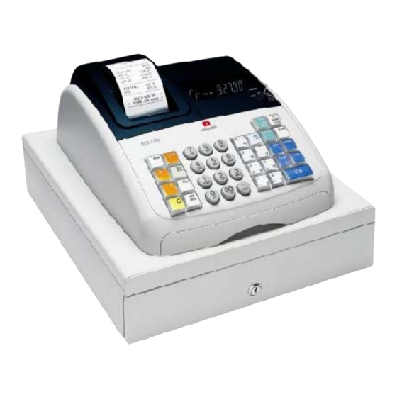
Page 7: Ecr7700 Exernal Components
________________________________________________________________________________________ ECR 7700 External Components With reference to figure: Customer Display Operator Display Control lock Keypad Cash Drawer ICash Drawer Lock Item deposit drawer Power Cord Customer Receipt Output Window Printer Compartment Cover Removable Cash Drawer and Box With reference to figure 4, the cash drawer has slots for banknotes and for coins. -
Page 8: Cash Register Specifications
________________________________________________________________________________________ ECR 7700 Technical Characteristics Listed below are the technical characteristics of this cash register model. Listed below are the technical characteristics of this cash register model. Type: Electronic cash register with clamshell thermal printer, 14 departments, 8 clerks, up to... -
Page 9: Safety Precautions
________________________________________________________________________________________ SAFETY PRECAUTIONS The power socket for this cash register must be located near the machine and must be easily Accessible. Do not use this cash register outdoors in the ram or near any liquid. MAINTAINING THE CASH REGISTER Provided below is information on how to maintain the cash register. Note: Before cleaning the cash register, make sure it Is powered off and/or unplugged from the wall outlet. -
Page 10: Unpacking And Setting Up The Cash Register
________________________________________________________________________________________ UNPACKING AND SETTING UP THE CASH REGISTER STANDARD ACCESSORIES The cash register comes with the following items: One black plastic journal winder spindle One roll of standard paper tape Three standard ‘AN’ size batteries for the battery back-up system The multilingual User’s Guide, Reference Guide in English and Warranty Card + Setup Poster A set of keys for looking the cash drawer Make sure that the cash register and all of the above items are included in the shipping canon. -
Page 11: Printr Compartment
________________________________________________________________________________________ PRINTER COMPARTMENT The printer compartment Is on the top Ieft-hand side of the cash register. It houses the thermal paper roll, journal winder spindle, back-up batteries and the thermal printer. This cash register uses standard 21/4” (57 mm) thermal paper. LOADING THERMAL PAPER FOR ECR 7100 Proceed as follows to Ioad the cash register with paper. - Page 12 ________________________________________________________________________________________ Lower the clamshell mechanism and secure it in place by pushing it all the way down until it clicks into pace. Replace journal winder with wheel to right of compartment. Pass the edge of the customer receipt through the receipt window on the compartment cover.
- Page 13 ________________________________________________________________________________________ Set the menu RECEIPT MODE switch to JOURNAL, press the [Feed] key and manually feed the paper into the slot until the paper catches and advances approximately six to ten inches above the print mechanism. Note: I the paper does not feed properly, check the alignment of the paper in the slot and/or for the straight edge on the end on the paper roll.
-
Page 14: Product Outline
________________________________________________________________________________________ 1. PRODUCT OUTLINE 1-1 HARDWARE The terminal uses 8-bits single chip microcomputer. The CPU has 128K bytes of internal Flash ROM and 6k bytes internal RAM, also used the 512K bytes S-RAM of external memory. This terminal uses 10-digits Union Jack green fluorescent display. This terminal also has a battery-backed up clock that keeps track of the month, day of the year, hour and minute. -
Page 15: Keyboard
________________________________________________________________________________________ 1-3 KEYBOARD The keyboard consists of Stroke 37 keys with key caps (except numeric keys). Y1117150 - 3 ECR7700 Service Manual... -
Page 16: The Keyboard For Ecr7700
________________________________________________________________________________________ 1-4THE KEYPAD FOR ECR 7700 The figure below shows the keypad layout 1-5KEYPAD FUNCTIONS The keys described here are those configured by default on the cash register keyboard, shown in figure 5. The symbol (*) indicates that the key is also used in caption programming. - Page 17 ________________________________________________________________________________________ Registers sales that are put on credit, such as a debit card, or on a credit card that is alternative to the one used for Charge tenders. Registers sales paid by check. Subtotals a sale, and used for the programming of VAT rates. Registers sales that are charged.
-
Page 18: Drawer
________________________________________________________________________________________ Clears an entry made from the numeric keypad or with before finalizing a before transaction with a Department or function key. Also used to clear error conditions. Registers a preset price of an individual item to the appropriate department. Used to subtract a percentage rate from an individual item or an entire sale. -
Page 19: System Block Diagram
________________________________________________________________________________________ 1-8 SYSTEM BLOCK DIAGRAM Rear Display 10digits Union Jack Printer Display Motor Front Display 10digits Union Jack Control Control Main CPU LTPZ225B μ PD78F0547 Key scans Print Control Return Mode Lock Keyboard Wind Motor Buzzer Drawer Sol. Driver EJ-RAM A0-A17 X’TAL 32.768KHz... -
Page 20: Diagnostic Software
________________________________________________________________________________________ 2. DIAGNOSTIC SOFTWARE 2-1. DIAGNOSTIC CHECK & FINISHED GOODS CHECK Diagnostic Software will check whether the machine works properly or not. It is already built in the machine and is always ready to boot this software by the following instructions. It is also useful to check after repairing the machine. - Page 21 ________________________________________________________________________________________ It means OK when no error occurs through the checkup. Y1117210 - 3 ECR7700 Service Manual...
- Page 22 ________________________________________________________________________________________ FINISHED GOODS CHECK LIST ECR7700 Service Manual Y111730 - 3...
-
Page 23: Software Version Check
________________________________________________________________________________________ 2-2. SOFTWARE VERSION CHECK Through the diagnostic check, it shows the software version in the beginning of the check. However, it is possible to check only the software version without diagnostic check. SOFTWARE VERSION CHECK 1) Input [960801] at PRG mode position. 2) VFD will show you the current software version Y1117230 - 3 ECR7700 Service Manual... -
Page 24: Assembly Instruction
________________________________________________________________________________________ 3. ASSEMBLY INSTRUCTION 3-1 TOP CASE UNIT APPLY SILICON OIL TO 1X2 KEY HOLE ONLY. KEY CAP KEY CAP FIX 25PCS BASE TOP TO KEY FRAME. T/SHEET BASE TOP (1X1) FIX KEY TOP SHEET TO KEY CAP THEN FIX ON BASE TOP KEY. NUM KEY BASE TOP (1X2) - Page 25 ________________________________________________________________________________________ PUT RUBBER SHEET TO KEY FRAME WITH FLAT. IT MUST BE ON FITTING BOSSES POSITION. FIX K/B PWB UNIT TO KEY FRAME BY FASTEN 11PCS SCREW. Y1117250 - 3 ECR7700 Service Manual...
- Page 26 ________________________________________________________________________________________ SLOT 2PCS PAPER ROLLER TO TOP CASE. (AS ON PICTURE 1) SLOT MOTOR SET PCS TO TOP CASE. (AS ON PICTURE 2) ECR7700 Service Manual Y111730 - 3...
- Page 27 ________________________________________________________________________________________ FIX CONTROL L/SWITCH UNIT TO TOP CASE BY FASTEN 2PCS SCREW. Y1117270 - 3 ECR7700 Service Manual...
- Page 28 ________________________________________________________________________________________ FIX VFD FILTER TO TOP CASE. (AS ON PICTURE 1) (10) MELT 5 POINT V/FILTER LEG TO TOP CASE. (AS ON PICTURE 2) ECR7700 Service Manual Y111730 - 3...
- Page 29 ________________________________________________________________________________________ (11) APPLY GLUE ON VFD FILTER LEG. (5 POINT) (LOCATION AS SHOWN ON PICTURE) (12) SLOT 2PCS BATTERY CONTACT TO TOP CASE. (AS SHOWN ON PICTURE) Y1117290 - 3 ECR7700 Service Manual...
- Page 30 ________________________________________________________________________________________ (13) CHECK AND CLEAN VFD FILTER AND MAIN PWB (DISPLAY TUBE). ECR7700 Service Manual Y111730 - 3...
- Page 31 ________________________________________________________________________________________ (14) FIX MAIN PWB UNIT TO TOP CASE BY FASTEN 4PCS SCREW. (15) FIX MOTOR UNIT TO MOTOR SET PIECE AND TURN ROUND THEN PRESS UNTIL IS LOCKED. Y1117310 - 3 ECR7700 Service Manual...
- Page 32 ________________________________________________________________________________________ (16) SLOT HARNESS ASSY TO FERRITE CORE AND TUNR 1 ROUND TO FERRITE CORE. (17) FIX PRINTER HEAD TO TOP CASE BY FASTEN 2PCS SCREW AND USE HARNESS ASSY. ( HARNESS ASSY MUST BE BEND 90° ) ECR7700 Service Manual Y111730 - 3...
- Page 33 ________________________________________________________________________________________ (18) INSERT PRINTER JOINER TO PRINTER CONNECTOR PWB. (AS ON PICTURE 1) (19) FASTEN 1PC SCREW TO PRINTER PWB AND TOP CASE. (AS ON PICTURE 2) (20) INSERT PRINTER PWB JOINER TO MAIN PWB. Y1117330 - 3 ECR7700 Service Manual...
- Page 34 ________________________________________________________________________________________ (21) SLOT BATTERY CONTACT (+/-) TO TOP CASE. (AS SHOWN ON PICTURE) (THE BATTERY CONTACT MUST BE PRESS UNTIL IS LOCK) (22) BAND BATTERY CONTACT (+) TO 90° AFTER INSERT. (23) STICK FILAMENT TAPE, BATTERY HARNESS TO TOP CASE. (FOLLOW THE PICTURE AS SHOWN ON PICTURE) ECR7700 Service Manual...
- Page 35 ________________________________________________________________________________________ (24) SETTING KEY FRAME TO TOP CASE. (25) INSERT CONTROL LOCK SWITCH CONNECTOR TO K/B PWB. Y1117350 - 3 ECR7700 Service Manual...
- Page 36 ________________________________________________________________________________________ (26) FIX FRONT SET PIECE TO TOP CASE BY FASTEN 5PCS SCREW. (LOCATION AS SHOWN ON PICTURE) ECR7700 Service Manual Y111730 - 3...
- Page 37 ________________________________________________________________________________________ (27) INSERT K/B PWB JUMPER LEAD TO MAIN PWB UNIT. (LOCATION AS SHOWN ON PICTURE) Y1117370 - 3 ECR7700 Service Manual...
- Page 38 ________________________________________________________________________________________ (28) LAST CHECKING THE SEMI SET. ECR7700 Service Manual Y111730 - 3...
-
Page 39: Drawer Unit Assy
________________________________________________________________________________________ 3-2 DRAWER UNIT ASSY APPREARANCE CHECK THE DRAWER UNIT. - NO WARPING & SCRATCHES FIX TRANSFORMER UNIT TO UPPER PLATE BY FASTEN 2PCS SCREW. Y1117390 - 3 ECR7700 Service Manual... - Page 40 ________________________________________________________________________________________ FIX FUSE HOLDER TO UPPER PLATE BY FASTEN 1PC SCREW. FIX CORD STOPPER TO AC CORD THEN FIX TO UPPER PLATE BY FASTEN 2PCS SCREW. ECR7700 Service Manual Y111730 - 3...
- Page 41 ________________________________________________________________________________________ FIX FUSE HOLDER PWB TO FUSE HOLDER BY FASTEN SCREW. [AS PICTURE 1.] FIX FUSE TO FUSE HOLDER. [AS PICTURE 2.] FIX FUSE CAP TO FUSE HOLDER BY TIED WITH INSULOCK TIE.[AS PICTURE Y1117410 - 3 ECR7700 Service Manual...
- Page 42 ________________________________________________________________________________________ SLOT 4PCS CIRCUIT BOARD SPACER TO DRAWER UNIT. (LOCATION AS SHOWN ON PICTURE) FIX P/S BOARD UNIT TO CIRCUIT B/SPACER. ECR7700 Service Manual Y111730 - 3...
- Page 43 ________________________________________________________________________________________ (10) INSERT DRAWER CABLE AND TRANSFORMER CABLE TO POWER SUPPLY BOARD UNIT. (LOCATION AS SHOWN ON PICTURE) (11) FIX HARNESS ASSY TO UPPER PLATE BY FASTEN 1PC SCREW AND USE GEAR WASHER Y1117430 - 3 ECR7700 Service Manual...
- Page 44 ________________________________________________________________________________________ (12) INSERT MOTOR CONNECTOR AND PRINTER JUMPER LEAD TO P/S BOARD UNIT. (LOCATION AS SHOWN ON PICTURE) ECR7700 Service Manual Y111730 - 3...
- Page 45 ________________________________________________________________________________________ (13) FIX SEMI SET TO DRAWER UNIT. (FOLLOW THE PICTURE AS SHOWN ON PICTURE) (14) FASTEN 1PC SCREW, TOP CASE TO DRAWER UNIT. Y1117450 - 3 ECR7700 Service Manual...
- Page 46 ________________________________________________________________________________________ (15) SLOT PRINTER ROLLER TO PRINTER ARM. (16) FIX PRINTER ARM TO TOP CASE. (AS ON PICTURE) ECR7700 Service Manual Y111730 - 3...
- Page 47 ________________________________________________________________________________________ (17) FIX DEPOSIT DRAWER TO ASSY UNIT. (AS SHOWN ON PICTURE) Y1117470 - 3 ECR7700 Service Manual...
- Page 48 ________________________________________________________________________________________ (18) SETTING THE 3PCS BATTERY, WINDING REEL AND ROLL PAPER TO ASSY UNIT. (19) FOLLOW CHECK LIST TO PERFORM FUNCTION CHECK. NO PRINTER NOISY & PRINTING MISSING DURING TESTING. IF ANY DEFECTIVE, PLS PUT IN DEFECTIVE BASKET. ECR7700 Service Manual Y111730 - 3...
-
Page 49: Circuitry
________________________________________________________________________________________ 4. CIRCUITRY 4-1 POWER SUPPLY CIRCUIT VP is generated using the 15.6V AC input across pins 1 and 2 of CN10. This AC voltage is rectified by the RS202 bridge rectifier and filtered by EC25 a 15000uF capacitor. The resulting DC voltage is about +18V. - Page 50 ________________________________________________________________________________________ POWER SUPPLY CIRCUIT continued ECR7700 Service Manual Y111730 - 3...
-
Page 51: Transformer Wirin Diagram
________________________________________________________________________________________ 4-2 TRANSFORMER WIRING DIAGRAM AC230V 50Hz Fuse 0218.500MXP Transformer CT-63E DC17V 400mA DC25V 100mA AC4V 230mA Y1117510 - 3 ECR7700 Service Manual... -
Page 52: Μpd 78F0547 Microcomputer
________________________________________________________________________________________ 4-3 μ PD78F0547 MICROCOMPUTER Port Assignment (μ PD78F0547) Por t # Pi n Speci f i cat i on Si gnal Si gnal Speci f i cat i on I / O Pi n I N I TI AL PF( Backup) Pi n N am e I / O Type N am e... - Page 53 ________________________________________________________________________________________ Port Assignment continued Por t # Pi n Speci f i cat i on Si gnal Si gnal Speci f i cat i on I / O Pi n I N I TI AL PF( Backup) Pi n N am e I / O Type N am e Ter m .
-
Page 54: Reset Circuit
________________________________________________________________________________________ 4-4 RESET CIRCUIT The following four operations are available to generate a reset signal. External reset input via RESET pin Internal reset by watching timer program loop detection Internal reset by comparison of supply voltage and detection voltage of power-on-clear(POC) circuit Internal reset by comparison of supply voltage and detection voltage of low-power-supply detector(LVI) ECR6700 adopts the (3) method. -
Page 55: Power Fail Circuit
________________________________________________________________________________________ 4-5 POWER FAIL CIRCUIT Power fail generated by a circuit using the PF DTC voltage. When power is on and the system is operating normally, the power fall signal stays at a higher voltage than 1.21V. The CPU watches power failure signals all the time. When power is on, PF is High level. When power down and CPU(U1)1pin voltage goes down lower than PF detection voltage(=1.21V), low-power-supply detector circuit of the CPU works and execute PF. -
Page 56: Display Circuit
________________________________________________________________________________________ 4-7 DISPLAY CIRCUIT Union Jack display (Front and rear ) This display is controlled by U3, PT6311 for VFD controller. Front display and Rear display are connected in parallel. DISPLAY CIRCUIT ECR7700 Service Manual Y111730 - 3... -
Page 57: Display Tube Information
________________________________________________________________________________________ 4-8 DISPLAY TUBE INFORMATION Display Digit (Union Jack) 10LY-01G Segment . (Union Jack) Display specification Display tube Front 10LY-01G (Union Jack) Rear 10LY-01G (Union Jack) Character size Front 14 mm (H) x 4.9 mm (W) Rear 14 mm (H) x 4.9 mm (W) Y1117570 - 3 ECR7700 Service Manual... -
Page 58: Keyboard Circuit
________________________________________________________________________________________ 4-9 KEYBOARD CIRCUIT Keyboard strobe line are the CPU port, this CPU port are P20-P22. Keyboard Return lines are the CPU port, this CPU port are P60-63 and P64-67. It is consist of matrix of Strobe line (8) × Return line (6). This ports’... - Page 59 ________________________________________________________________________________________ KEYBOARD CIRCUIT continued Dial Switch Board MDRTN SCAN0 SCAN1 REG1 SCAN2 SCAN3 REG2 SCAN4 SCAN5 2mm Pitch Board-in 2mm Pitch Board-in SCAN0 SCAN1 SCAN2 SCAN3 SCAN4 SCAN5 SCAN6 SCAN7 RETURN0 RETURN1 RETURN2 RETURN3 RETURN4 RETURN5 MDRTN 1N4148 1N4148 1N4148 1N4148 1N4148 1N4148...
-
Page 60: Drawer Circuit
________________________________________________________________________________________ 4-10 DRAWER CIRCUIT The solenoid for a drawer is activated using the signal P130 from the CPU. This signal is normally Low, and goes High to cause the drawer to run. When P130 is High, Q10 is on. Current flow through the transistor cause the collector to be held Low, near ground potential. CN12 RL102-E B3P-SHF-1AA... -
Page 61: Battery Circuit
________________________________________________________________________________________ 4-12 BATTERY CIRCUIT VBB voltage is used Battery or VCC voltage. The batteries are connect the CN2, through the diode at D1. VBB goes to the CPU and external RAM, for backup voltage. Battery specification Type : SUM-3 × 3 Voltage: 4.5V *RESISTOR (Dip) 9.1K/F (Dip) -
Page 62: Externalmemory
________________________________________________________________________________________ 4-13 EXTERNAL MEMORY 128K bytes S-RAM (BS62LV1027) used as an external RAM for PLU and electric Janal and etc. P70 through P77 are multiplex bus consists of data bus (D0-D7). P40 through P47 are multiplex bus consists of data bus (A0-A7). P50 through P53 are multiplex bus consists of data bus (A8-A11). -
Page 63: Printer Circuit
________________________________________________________________________________________ 4-14 PRINTER CIRCUIT STEP MOTOR The motor drives with 2-2 phase excitation. One step of the motor drive signal feeds the paper 0.125mm. One dot line is configured by 2 steps. When the voltage signal shown in below Figure is input to U5, the printer feeds the paper in the normal direction when the motor is excited in the order of step 1, step 2, step 3, step 4, step 1, step 2,……, as shown in below Table. - Page 64 ________________________________________________________________________________________ PRINTER CIRCUIT continued Table: Terminal Assignments of the Printer Mechanism Connecting Terminal Terminal Signal Name Description Number SENS1 Mechanical switch signal SENS2 Mechanical switch signal Head drive power Head drive power DATA Print data input (serial input) LATCH# Print data latch (memory) CLOCK Print data transfer synchronization signal Logic power (5V)
- Page 65 ________________________________________________________________________________________ PRINTER CIRCUIT continued VH VCC 100 (Dip) P_CLK CLOCK P_LAT# DST4# 100 (Dip) P_DAT DATA P_SEN SENS1 P_DST1# DST1# 100 (Dip) P_DST4# P_DST3# 100 (Dip) P_DST2# 52147-0810 P_TH TCH# PM_B# OUT4 PM_B M_PH4 OUT3 PM_A M_PH2 OUT1 PM_A# M_PH1 OUT2 M_PH3 52147-1310...
-
Page 66: Curcuit Digram
________________________________________________________________________________________ 5. CIRCUIT DIAGRAM DSP_CS1# DSP_CS1# DSP_DATA DSP_DATA DSP_CLK DSP_CLK BUZZER BUZZER 100k x 8 DRAWER DRAWER VH VCC 0.1uF CLOCK 100 (Dip) P_CLK KSCN0 KSCN0 CLOCK LATCH# P_LAT# KSCN1 KSCN1 DST4# DATA 100 (Dip) P_DAT KSCN2 KSCN2 DATA P_SEN KSCN3 KSCN3 SENS1... - Page 67 ________________________________________________________________________________________ CIRCUIT DIAGRAM continued VFD1 VFD2 10-LY-01G 10-LY-01G VFDL_10G VFDL_9G VFDL_8G VFDL_7G VFDL_6G VFDL_5G VFDL_4G VFDL_3G VFDL_2G VFDL_1G VFDL_Line VFDL_com VFDL_DP VFDL_r VFDL_p VFDL_n VFDL_m VFDL_k VFDL_j VFDL_h VFDL_g VFDL_f VFDL_e VFDL_d2 VFDL_d1 -Vpw VFDL_c VFDL_b VFDL_a2 VFDL_a1 PT6311 S12/K12 SG11/KS11 SG10/KS10 SG9/KS9...
- Page 68 ________________________________________________________________________________________ CIRCUIT DIAGRAM continued CN12 RL102-E 0 (Dip) DRAWER B3P-SHF-1AA DRW_ON 4.7K 4.7K (Dip) KPT-G1720-5V 2SD986 18 ohm_1W (Dip) 4.7K 2SC2412 RL102-E Winding Motor 0.1uF B3B-XH RL102-E 4.7K 2SC3242A AC230V 50Hz 2.2K RL102-E CA21-453-2 4.7K 2SD1415A 2SA1036 CN11 EC24 *Fuse P_VHON1 *0218.500MXP 4.7K (Dip)
- Page 69 ________________________________________________________________________________________ CIRCUIT DIAGRAM continued Dial Switch Board MDRTN SCAN0 SCAN1 SCAN2 REG1 SCAN3 REG2 SCAN4 SCAN5 2mm Pitch Board-in 2mm Pitch Board-in SCAN0 SCAN1 SCAN2 SCAN3 SCAN4 SCAN5 SCAN6 SCAN7 RETURN0 RETURN1 RETURN2 RETURN3 RETURN4 SCAN0 SCAN1 SCAN2 SCAN3 SCAN4 SCAN5 SCAN6 SCAN7...
-
Page 70: Exploded Diagram
________________________________________________________________________________________ ________________________________________________________________________________________ 6. EXPLODED DIAGRAM 6. EXPLODED DIAGRAM ECR7700 Service Manual ECR7700 Service Manual Y111730 - 3 Y111730 - 3...
Need help?
Do you have a question about the ECR 7700 and is the answer not in the manual?
Questions and answers