
Subscribe to Our Youtube Channel
Related Manuals for Custo Med Bicycle Ergometer ec3000e


Summary of Contents for Custo Med Bicycle Ergometer ec3000e
- Page 1 Operating manual Bicycle Ergometer ec3000e GEB-0179 / DK-1334 Version 001 - 12.09.2013...
- Page 2 No part of this manual may be reprinted, translated or reproduced without the manufacturer's written permission. This manual is not subject to any change order service. Please contact the manufacturer for the latest document revision. custo med GmbH Leibnizstraße 7 85521 Ottobrunn...
-
Page 3: Table Of Contents
ontents Declaration of Conformity General Information Safety Information Intended Use Setup and Mains Connection Controls and Indicators Transport Setup Mounting the Control Terminal (P or K) Connecting the Power Cord Connecting the ECG Cable Connecting the Blood Pressure Cuff Preparing the Patient Adjusting the Saddle and the Handlebar Preparing the Patient for Blood Pressure Measurements Checking the Cuff Tubing... - Page 4 - 4 -...
-
Page 5: Declaration Of Conformity
eClaration of onformity EG-KONFORMITÄTSERKLÄRUNG / DECLARATION OF CONFORMITY Wir / We ergoline GmbH Lindenstr. 5 72475 Bitz (Germany) erklären in alleiniger ec3000e Verantwortung,dass das Medizinprodukt / declare on our own responsibility that the medical device Modelle / Models 17000 ec3000e und das Zubehör / and the 17001 Sattelverstellung mit Motor accessories 17002 Autom. Blutdruckmessung 17003 SpO2-Messung 17004 Sattelverstellung, horizontal 17005 Manschette, Zugbügel, Standard 17006 Manschette, Zugbügel, XL 17007 Manschette, Zugbügel, Kind... - Page 6 - 6 -...
-
Page 7: General Information
Paragraphs with special symbols are of particular ‑ the equipment is used in accordance with the importance. instructions given in this operator's manual. • If unauthorized individuals open the control terminal, damaging the calibration sticker, any warranty claim shall become void. custo med GmbH • This manual reflects the equipment specifications Leibnizstraße 7 and applicable safety standards valid at the time of 85521 Ottobrunn printing. All rights are reserved for devices, circuits, Germany techniques, software programs, and names appearing in this manual. Phone: +49-(0)-89 710 98-00 Fax: +49-(0)-89 710 98-10 • On request custo med will provide a Field Service e-mail: info@customed com Manual. - Page 8 Tel : +49-(0)-7431 - 9894 -0 Fax: +49-(0)-7431 - 9894 -128 Email: info@ergoline com Internet: www ergoline com istributeD by custo med GmbH Leibnizstraße 7 85521 Ottobrunn Germany Tel : +49 89 710 98-00 Fax: +49 89 710 98-10 Email:...
-
Page 9: Safety Information
In case of questions, please contact your custo med dealer or the custo med GmbH Service Department. For use, the ergometer must always be connected to electric Warning installations that fulfill the local requirements. -
Page 10: Intended Use
‑i ‑ afety nformation for ntenDeD ‑ vasive looD ressure easure The ec3000e is a computer‑controlled medical e rgometer. ment At pedal speeds between 30 and 130 RPM and loads between 6 and 999 watt, the ergometer operates indepen‑ dent of the pedal speed. Warning The speed‑independent range is shown in the Appendix • Patient Hazard • (Technical Specifications). The ec3000e ergometer may only be used in exercise test‑ Do not take blood pressure measurements with a cuff on ing as well as for rehabilitation of cardiac and cardiovas‑ patients suffering from sickle cell anemia or where skin lesions cular patients according to the instructions given in this are likely to occur. - Page 11 - 11 -...
-
Page 12: Setup And Mains Connection
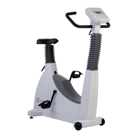
etuP anD ains onneCtion ontrols anD nDiCators 1 Control terminal 2 Blood pressure cuff connection (option) 3 Adjustment of the handlebar angle 4 Blood pressure cuff 5 Adjustment of the handlebar height (ec3000e only) 6 Castors 7 Speed display (RPM) for patient 8 Adjustment of the saddle height 9 Digital saddle height indication (option) 3000 10 Power switch (green button) controls connections and indicators 11 Sockets for power cord and connection cables ( underside of ergometer) 12 Levelling devices to adjust the ergometer to uneven floors - 12 -... -
Page 13: Transport
ransPort For short distances, the ec3000e can be lifted at the saddle Caution and rolled away on its castors. • Equipment Damage • To cover greater distances, however, we recommend the following method: Avoid strong vibrations of the ec3000e during transport. • Disconnect the power cord from the wall outlet. • Rotate the handlebar towards the front. Tighten the clamping lever. • Stand in front of the ec3000e, grasp the handlebar and tilt the ec3000e towards you until it is standing on the castors only and is balanced. • It is now possible to transport the ec3000e. • When you have reached the new location, lower the ec3000e very carefully to avoid damage. 3000 ransporting the ec etuP Place the ec3000e on a level floor. The ec3000e must be set up in a secure and stable position ‑ the two levelling feet at the back make for easy adjust‑ ment to uneven floor surfaces. Extend the foot concerned until the ec3000e no longer wobbles. -
Page 14: Mounting The Control Terminal (P Or K)
ountinG the ontrol erminal The control terminal can be installed with the display either facing the patient or the operator. It is recommended to install the terminal with the display and control keys towards the operator and the speed display towards the patient. ifferent orientations of the control terminal onneCtinG the ower Set the handlebar to the front upper position and secure. Tilt the ec3000e carefully towards you until it rests on the handlebar 3000 ssembly position of the ec e ergometer Caution • Equipment Damage • Before connecting the ergometer to the power line, check that the line voltage corresponds to the ratings on the type plate. - Page 15 The connection panel is located on the underside of the ergometer. • Plug the power cord into socket (a) and use the sup‑ plied lock (b) to secure it against disconnection. • Using the supplied strain relief, attach the cable to the metal frame. onnection panel Power input Lock ower cord with installed strain relief Hint • disconnection • Removing the power cord results in complete disconnection from mains (all poles). Danger • Patient Hazard • To insure a safe connection to the protective ground system, power cords of type „hospital only“...
-
Page 16: Connecting The Ecg Cable
Digital connection RS232 (remote control by PC or ECG recorder, Hint • connecting cables • Only use connecting cables released by custo med. To use the integrated USB connector, a special driver is required - contact custo med. - 16 -... -
Page 17: Connecting The Blood Pressure Cuff
onneCt nG the looD ressure • Connect the microphone at (1). • Slip the cuff tubing onto the fitting (2) and engage. To disconnect, push back the connector's knurled sleeve. Artifacts that may be caused by patient movements during the exercise test, must be avoided if possible, while the lood pressure cuff connections blood pressure is being taken. Microphone connection Therefore, do not forget to attach the cuff tubing to the Cuff tubing handlebar with the supplied Velcro tape: • Open the large Velcro tape and wrap around handlebar. • Secure the cuff tubing with the small Velcro tape, but do not exert pressure on the tubing. elcro tape to secure the cuff tubing Caution • Equipment Damage • Avoid strong vibrations of the ergometer during transport. -
Page 18: Preparing The Patient
reParinG the atient DjustinG the aDDle anD the anDlebar On the ec3000e, you adjust the saddle height manu‑ ally with a clamping lever. Optional, the saddle height is electrically adjusted with the corresponding keys on the control terminal (the display below the saddle indicates the saddle height). With the pedal in the bottom position, the angle between the axis formed by the upper body and the thigh should be approximately 10°. Set the handlebar to a position where the patient sitting upright on the saddle can reach it easily. To do so, open clamping lever 1 and set the handlebar to a suitable angle. On the ec3000e 200, the height of the handlebar can ad‑ ditionally be adjusted with clamping lever 2 ‑ the horizon‑ tal bar should be approximately at the samel level as the saddle. djusting saddle and handlebar Adjustment of the handlebar angle Adjustment of the handlebar height (ec3000e 200 only) Adjustment of the saddle height (ec3000e 100 only) Saddle height display (ec3000e 200 only) Note... -
Page 19: Preparing The Patient For Blood Pressure Measurements
reParinG the atient for looD ressure easurements Always choose the cuff size suitable for the patient's arm. The maximum arm circumference is indicated on the cuff. orrect cuff size rong cuff size iCroPhone osition Before applying the cuff, check the position of the micro‑ phone inside the red pocket (on the inside of the cuff): When the microphone is inside the pocket, its metal side must face the arm. orrect microphone position PPlyinG the The center of the microphone must be located exactly on the brachial artery. Locate the artery by palpation, if required. The red tab identifies the position of the micro‑ phone. The accurate placement of the microphone is the primary condition for reliable pressure measurement during exer‑ cise tests. The cuff must be applied directly on the skin, it may not be applied on top of clothing, paper, etc. Apply the cuff a pprox. 2 cm above the bend of the elbow. The cuff should be tight, but it should not constrict blood vessels. -
Page 20: Checking The Cuff Tubing
When you close the Velcro strap, check that the metal clasp (a) is inside the marked index range (b), and not outside. The cuff tab must be located below the metal clasp (see illustration at right). orrect cuff position heCKinG the ubinG Check that the cuff tubing does not knock against the patient's knee, when the patient is pedalling and the hand is on the handlebar. Secure the cuff tubing with the Velcro tape attached to the handlebar. Instruct your patient to move as little as possible during a blood pressure measurement and, in particular, to avoid excessive contractions of the muscles in the upper arm. istance between Knee and tubing Caution • Patient Hazard • Apply the cuff directly on the skin. Make sure that rolled up sleeves do not impede blood circulation in the upper arm. -
Page 21: Attaching The Spo2-Sensor
o2‑s ttaCh nG the ensor Place the index finger into the SoftTip sensor. The cable should run on top of the hand. After some seconds the actual SpO2 value is displayed on the recorder display.. o2-s ttach ng the ensor o2‑s ensors oPtion - 21 -... -
Page 22: Operation Control Terminal
Peration ontrol terminal Control terminal urninG the ystem You turn the ergometer on by pressing the power switch ‑ the green indicator in the switch lights up. The ergometer runs a self‑test. Subsequently, the main menu displays. Selftest running Note test screen • Instruct the patient not to pedal while the ergometer is being turned on and during the self-test. • Apply the blood pressure cuff to the patient AFTER the er- gometer has been turned on and the self-test completed. -
Page 23: Operating Modes
PeratinG oDes An ec3000e ergometer supports the following operating modes: PC MODE An external device (e.g. stand‑alone electrocardio‑ graph, PC‑based ECG system) controls the ergometer ‑ no intervention at all is required at the ergometer. ERGOMETRY The ergometer runs an automatic exercise test ‑ some of the corresponding test protocols are user‑configu‑ rable and stored in the system (see chapter "Settings"). MANUAL The ergometer is controlled manually, i.e., the user performs all load changes via the keypad. SETTINGS Used to configure the ergometer. PeeD reaDout At the top of the control terminal, there is a speed readout for the patient as well as three LEDs that inform the p atient of the speed: too slow, too fast or correct. The ranges for the respective speed ratings depend on the selected load (see "Technical Specifications"). peed readout speed low (patient should pedal faster) correct speed speed high (= patient should pedal slower) Note •... -
Page 24: Pc Mode
PC m Use the softkeys on the right and left (↑ ↓) to position the PC Mode bar cursor on PC MODE and confirm the selection with Ergometry SELECT. Manual Settings ↑ ↓ Select ain menu The display changes ‑ the ergometer is waiting for com‑ mands from the external ECG unit. With the arrrow keys, the saddle height can be electrically adjusted on the ec3000e 200 (on the ec3000e 400, these keys adjust the height of the drive unit). Saddle nitial screen As soon as the ergometer receives commands from the controlling ECG unit or PC, the exercise test will start and the corresponding values will be displayed. The exercise test can only be terminated with the corre‑ sponding command from the controlling ECG unit. PC Mode isplay during exercise test current load in watts most recent BP value (systolic/diastolic values) or during inflation cuff pressure and indicator for micro- fone signal amplitude (see below) duration of exercise test (min) -
Page 25: Ergometry
rGometry Use the softkeys on the right and left (↑ ↓) to position the PC Mode bar cursor on ERGOMETRY and confirm the selection with Ergometry SELECT. Manual Settings Select ain menu Protocols The stored test protocols available for selection will be displayed. There are five fixed protocols (protocols 1 to 1. WHO 5, see Appendix) , whereas protocols 6 to 15 are user‑ 2. BAL programmable. 3. Hollmann The protocol menu provides an overview of the test 4. STD. France phases: 50 W / 2 min / 25 W 5. Standard e.g.: means: step protocol Select initial (basic) load 50 watts stage time 2 minutes load increment 25 watts electing an exercise test protocol 30 W / 25 W/min means: ramp protocol initial (basic) load 30 watts... - Page 26 Note • The saddle height (ec3000e 200) can be changed during an exercise test. • To reactivate the saddle height adjustment function, press and the arrow keys will again be displayed. • Additional blood pressure measurements can be initiated with erminatinG an xerCise The exercise phase can be terminated manually at any time...
-
Page 27: Manual
anual Use the softkeys on the right and left (↑ ↓) to position the PC Mode bar cursor on MANUAL and confirm the selection with Ergometry SELECT. Manual Settings In this operating mode the user controls the entire exercise test by selecting the loads, stage times and by initiating blood pressure measurements. Select ain menu The exercise test is started with the "Start" key, afterwards the load can be set and changed with the +5 W and ‑5 W keys (in increments of +/‑1 W up to +/‑25 W, as config‑ ured). Blood pressure measurements an be initiated with + 5 W + 5 W Start - 5 W - 5 W nitial screen of a manual exercise test erminatinG an xerCise The exercise test can be terminated manually at any time with the END key located in the middle. The load will immediately drop to 0 watt. There is no recovery phase in the manual mode. + 5 W - 5 W creen display during the test - 27 -... -
Page 28: Settings With Control Terminal P
ettinGs with ontrol erminal Some of the device settings are configurable to meet spe‑ PC Mode cific requirements. The settings will be saved and remain Ergometry stored even when the ergometer is switched off. Manual Use the softkeys on the right and left (↑ ↓) to position the Settings bar cursor on SETTINGS and confirm the selection with SELECT. The configuration menu displays. Select When all changes have been made, you can exit the con‑ ain menu figuration menu with the key. Settings Default Mode Use the softkeys on the right and left (↑ ↓) to position the Protocols bar cursor on the parameter to change and confirm the Contrast selection with SELECT. Load Change Language Select onfiguration menu Default Mode efault Menu In this menu you choose the default mode activated when PC Mode the ergometer is turned on. When first turned on, the Ergometry ergometer will display this menu. - Page 29 Protocol Use the right and left softkeys ↑ ↓ to select the parameter to edit. Select Step Basic Load 25 W Stage Time 2 min Load Stage 25 W Select electing the parameter to edit Protocol When confirmed with SELECT, the corresponding value ap‑ pears in reverse video and can be changed with the arrow Select Step keys ↑ ↓. Basic Load 25 W Stage Time 2 min Load Stage 25 W Pressing SELECT will save the new value. Select All other parameters are edited in the same way. You exit the configuration with diting the parameter value Contrast ontrast The display contrast is adjustable in the range from 50 % 0 to 100%.
- Page 30 Language anGuaGe Deutsch The texts can be displayed in different English languages. Francais Espanol Italiano Auswahl anguage menu Beep The audio signal emitted during blood pressure measure‑ ments can be turned on and off. Off Select eep during measurements oftware ersion Select this option to view the installed software version. Date To begin with, you select DATE or TIME and confirm the 22. 08. 2007 selection. Then the value displayed in reverse video can be edited with the ↑ ↓ keys and saved with SELECT. Time The time is adjusted in the same way. 17 : 33 : 05 Select You exit the configuration with etting the date Date 22. 08. 2007 Time 17 : 33 : 05 Select etting the day - 30 -...
- Page 31 eKG t EKG Type The selected EKG Type determines the communication method with the ECG recorder, PC‑based ECG system, etc. To prevent an accidental change of this setting, the menu is protected with a password. Using the arrow keys, enter 003 and confirm the entry with SELECT. Select eKg t ntering the ype password All ec3000e ergometers support the following communica‑ tion modes: • Analog with pulse Remote start mode; prior the each load change, the ergometer generates a control pulse and sends the corresponding data via the interface. • Analog / Digital An analog voltage controls the load ‑ blood pressure measurements can be initiated with digital commands. • Digital (default) The communication with the ergo m eter is entirely controlled with digital commands. EKG Type • Analog IN‑OUT Analog with pulse The entire communication (load control and BP mea‑ Analog / Digital surements) is controlled with analog signals. Digital No digital data will be sent.
-
Page 32: Cleaning, Maintenance, Disposal
leaninG aintenanCe isPosal Warning eneral leaninG • Shock Hazard • Wipe the device surface down with a cloth moistened with soap water or a disinfectant. • Disconnect the device from the power line before clean- The cloth should not be dripping wet; do not allow liquids ing. to enter the device. • Equipment Damage • Recommendeddisinfectants are, for example: ‑ Fugaten spray ‑ Lysoform or • Do not allow liquids to enter the equipment. ‑ Promanum N Devices into which liquids have entered must be immedi- ately cleaned and checked by a service technician, before... - Page 33 leaninG the looD ressure emovinG the iCroPhone Pull the end of the cuff through the metal clasp and fold out the cuff. Pull on the short Velcro tab to open the microphone pocket and carefully remove the microphone. emoving the icrophone Warning leaninG isinfeCtion • Equipment Damage • Clean the cuff and tubing with a moist cloth. You can use a dishwashing liquid or mild soap water. • Cuff, microphone and tubing may not under any circum- stances: Clean the microphone with a cloth moistened with alcohol - be immersed in liquids or soap water.
- Page 34 leaninG anD DisinfeCtion of iP sensor Aids for cleaning / disinfection: • Approved cleaning and disinfecting agent without protein‑fixing effect (always observe the recommendations of the manufacturer when mixing). • Compressed air • Soft, disposable cloths • Automated cleaning brushes • Demineralised water Commercially available cleaning and disinfecting agents approved for this purpose and based on aldehydes, alco‑ hols, amines, bases or quaternary ammonium compounds are suitable for cleaning and disinfecting the SpO2 sensors as long as they exhibit similar active ingredient composi‑ tions and concentrations to the examples listed below. Productname Manufacturer Gigasept Instru AF (Glycoderivat) Schülke & Mayr GmbH Manual cleaning and disinfection www.schuelke‑mayr.com Gigasept FF (Aldehyd) Manual cleaning and disinfection Perfektan TB Dr. Schumacher GmbH Manual disinfection www.schumacher‑online.com Descoton forte (Aldehyd) Manual disinfection...
- Page 35 Safety information 5. Clean all surfaces of the sensor (inside and outside) applicable standards with a brush or disposable cloth and cleaning agent or disinfectant (observe manufacturer‘s instructions). We recommend turning the silicone housing of the sensor inside out for cleaning of the inside surfaces. The • SoftTip sensors are NOT suitable for SoftTip sensors can be submersed in cleaning liquid being autoclaved or machine cleaning. (see Tab: List of approved cleaning agents). • SpO2 sensors must not be cleaned in ultrasound baths. 6. Now rinse the sensor for at least 1 minute in appro‑ This process will destroy the sensors. ximately 200 ml of fully demineralised water. When doing so, the water must flow into the connector and •...
- Page 36 aintenanCe heCKs before eaCh use Before each use, visually inspect the device for signs of damage. If you detect damages or impaired functions which may result in a hazard to the patient or the operator, the device must be repaired before it can be used again. eChniCal afety nsPeCtions anD eChniCal nsPeCtions of the easurinG ystem The technical safety inspections and the inspections of the measuring system must be completed every two years according to the rules of the art by a Service Engineer authorized by custo med. Similarly, the automatic sphygmomanometer in the control terminal must be checked and calibrated by an authorized specialist every two years to fulfill legal requirements. The date of the next inspection is indicated on the inspection sticker attached next to the type plate on the e rgometer. isPosal The product described in this operator manual must not be disposed as unsorted municipal waste and must be col‑ lected separately. Please contact an authorized representative of the manu‑ facturer for information concerning the decommissioning of your equipment. - 36 -...
-
Page 37: Technical Specifications
eChniCal PeCifiCations rGometer Model modular ergometer system ec3000e Operating Mode continuous operation Power 100 ‑ 240 V / 50 ‑ 60 Hz (60 VA max.) specification power cord US: SJT 2xAWG16 125 V / 10 A „hospital“ or „ hospital grade“ specification internal backup battery: IEC: CR 2032 / 3 V 230 mAh Braking Principle computer‑controlled eddy current brake with torque measurement; speed independent to DIN VDE 0750‑0238 Load Range 6 ‑ 999 watts, speed independent (see diagrams) Speed Range 30 to 130 RPM Deviation of Measured Load to DIN VDE 0750‑0238 Load Increments user programmable Internal Protocols... - Page 38 Interfaces PORT 1 (DSUB‑9‑pole): digital remote control RS232 by PC or ECG recorder, remote start of ECG recorder (optional) USB: digital remote control by PC (driver required) Dimensions, Weight length: 900 mm width: 460 mm (width of handlebar: approx. 575 mm) height: 900 mm to 1350 mm weight: approx. 68 kg Safety Standards DIN EN 60601‑1, DIN EN 60601‑1‑2, DIN VDE 0750‑238 Protection Class / Degree of Protection II / B (to DIN EN 60601‑1) BF (with blood pressure module) MDD Classification class IIa to 93/42 EEC RF Emission class B to DIN EN 55011 / 5.0 DIN EN 60601‑1‑2 Environment operation: temperature: +10 to +40 °C (50 to 104 °F) rel. humidity: 30 to 75%, no condensation...
- Page 39 Cuff Deflation Method pulse‑dependent deflation rate approx. 3 mmHg/beat or approx. 3 mmHg/s Calibration calibration with external pressure meter Artifact Rejection automatic artifact rejection and comparison of the rest‑ ing BP readings from both methods for plausibility xerCise rotoCols Protocol initial load time in stage load recovery load recovery time [min] increment [min] 1. WHO 2. BAL 3. Hollmann 4. STD France 5. Standard 6. ‑ 15. (user‑programmable) Adjustment Range 20 ‑ 100 1 ‑ 30 1 ‑ 400 1 ‑ 99 - 39 -...
- Page 40 amily of CharaCteristiCs of the braKinG torque Control ranGe black: speed‑independent range to DIN VDE 0750‑0238 black + grey: speed‑independent range of the ec3000e ergometer ieC 60601‑1 amily of CharaCteristiCs of the loaD PerioDs aCCorDinG to Under permanent load, the load periods and pauses (white) shall be observed. - 40 -...
-
Page 41: Electromagnetic Compatibility En 60601-1-2
Warning leCtromaGnetiC omPatibility • RF INTERFERENCE • en 60601‑1‑2 • Use of portable telephones or other radio frequency (RF) Changes or modifications to this system not expressly emitting equipment near the system may cause unexpected or approved by ergoline could cause EMC issues with this or adverse operation. - Page 42 ’ – e uiDanCe anD anufaCturer eClaration leCtromaGnetiC mmunity The ergoselect ergometer is intended for use in the electromagnetic environment specified below It is the responsibil- ity of the customer or user to ensure that the ergoselect ergometer is used in such an environment ImmunityTest IEC 60601 Test Level Compliance Level...
- Page 43 ’ – e uiDanCe anD anufaCturer eClaration leCtromaGnetiC mmunity The ergoselect ergometer is intended for use in the electromagnetic environment specified below It is the responsibil- ity of the customer or user to ensure that the ergoselect ergometer is used in such an environment ImmunityTest IEC 60601 Test Level Compliance Level...
- Page 44 eCommenDeD seParation DistanCes between Portable anD mobile CommuniCations equiPment anD the erGoseleCt erGometer The ergoselect ergometer is intended for use in the electromagnetic environment in which radiated RF disturbances are controlled The customer or the user of the ergoselect ergometer can help prevent electromagnetic interference by maintaining a minimum distance between portable and mobile RF communications equipment (transmitters) and the ergoselect ergometer as recommended below, according to the maximum output power of the communications equipment Rated Maximum...
- Page 46 GmbH Leibnizstraße 7 85521 Ottobrunn Germany Phone: +49 89 710 98-00 Fax: +49 89 710 98-10 Email: info@customed.de Internet: www.customed.de...
Need help?
Do you have a question about the Bicycle Ergometer ec3000e and is the answer not in the manual?
Questions and answers