Asus Terminator 2 Barebone System T2-AH1 Product Manual
Asus t2-ah1 terminator 2 barebone system product manual
Hide thumbs
Also See for Terminator 2 Barebone System T2-AH1:
- Driver installation (1 page) ,
- Quick reference manual (56 pages)
Table of Contents
Advertisement
Quick Links
Advertisement
Table of Contents

Related Manuals for Asus Terminator 2 Barebone System T2-AH1


Summary of Contents for Asus Terminator 2 Barebone System T2-AH1
- Page 1 Terminator 2 Barebone System Model T2-AH1...
- Page 2 Product warranty or service will not be extended if: (1) the product is repaired, modified or altered, unless such repair, modification of alteration is authorized in writing by ASUS; or (2) the serial number of the product is defaced or missing.
-
Page 3: Table Of Contents
Table of contents Notices ... vi Safety information ... vii About this guide ... viii System package contents ... x Chapter 1: System Introduction Chapter 1: System Introduction Chapter 1: System Introduction Chapter 1: System Introduction Chapter 1: System Introduction Welcome! ... - Page 4 Creating a bootable floppy disk ... 5-2 5.1.2 ASUS EZ Flash utility ... 5-3 5.1.3 AFUDOS utility ... 5-4 5.1.4 ASUS CrashFree BIOS 2 utility ... 5-6 5.1.5 ASUS Update utility ... 5-8 BIOS setup program ... 5-11 5.2.1 BIOS menu screen ... 5-12 5.2.2...
- Page 5 Table of contents 5.2.5 Sub-menu items ... 5-13 5.2.6 Configuration fields ... 5-13 5.2.7 Pop-up window ... 5-13 5.2.8 Scroll bar ... 5-13 5.2.9 General help ... 5-13 Main menu ... 5-14 5.3.1 System Time ... 5-14 5.3.2 System Date ... 5-14 5.3.3 Legacy Diskette A ...
-
Page 6: Notices
Notices Federal Communications Commission Statement Federal Communications Commission Statement Federal Communications Commission Statement Federal Communications Commission Statement Federal Communications Commission Statement This device complies with Part 15 of the FCC Rules. Operation is subject to the following two conditions: • This device may not cause harmful interference, and •... -
Page 7: Safety Information
Safety information Electrical safety Electrical safety Electrical safety Electrical safety Electrical safety • To prevent electrical shock hazard, disconnect the power cable from the electrical outlet before relocating the system. • When adding or removing devices to or from the system, ensure that the power cables for the devices are unplugged before the signal cables are connected. -
Page 8: Motherboard Layout
Audience Audience This guide provides general information and installation instructions about the ASUS T2-AH1 barebone system. This guide is intended for experienced users and integrators with hardware knowledge of personal computers. How this guide is organized How this guide is organized... -
Page 9: Conventions Used In This Guide
A S U S W e b s i t e s A S U S W e b s i t e s The ASUS websites worldwide provide updated information on ASUS hardware and software products. Refer to the ASUS contact information. -
Page 10: System Package Contents
A S U S T 2 - A H 1 b a r e b o n e s y s t e m with A S U S T 2 - A H 1 b a r e b o n e s y s t e m • ASUS motherboard • 250 W PFC power supply unit •... - Page 11 Chapter 1 This chapter gives a general description of the ASUS T2-AH1. The chapter lists the system features including introduction on the front and rear panel, and internal components. A S U S T 2 - A H 1 A S U S T 2 - A H 1...
-
Page 12: Chapter 1: System Introduction
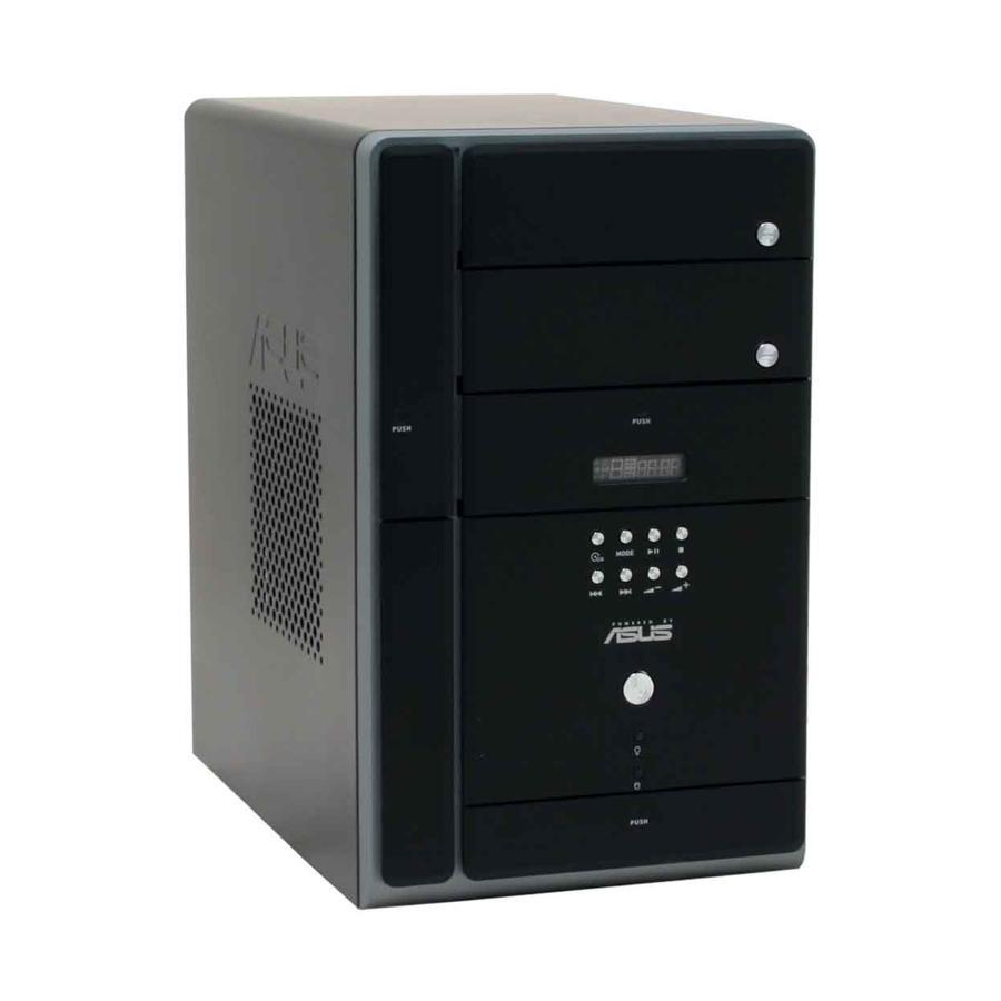
The ASUS T2-AH1 is an all-in-one barebone system with a versatile home entertainment feature. The system comes in a stylish mini-tower casing, and powered by the ASUS motherboard that supports the AMD Athlon with 1 GHz/800 MHz/400 MHz FSB and up to 2 GB system memory. -
Page 13: Drive Bay
1 . 1 . F l o p p y d r i v e d o o r . F l o p p y d r i v e d o o r . F l o p p y d r i v e d o o r . Open this door to access the floppy disk drive. F l o p p y d r i v e d o o r . - Page 14 1 4 . 1 4 . 1 4 . S T O P b u t t o n S T O P b u t t o n ..Press this button to stop the audio track being S T O P b u t t o n S T O P b u t t o n 1 4 .
-
Page 15: Front Panel (Internal)
Front panel (internal) The optical drive(s), storage card reader slots, and several I/O ports are located inside the front panel doors. Open the front panel doors by pressing the 1 9 . 1 9 . F l o p p y d i s k d r i v e . F l o p p y d i s k d r i v e . - Page 16 2 5 . 2 5 . 2 5 . 2 5 . 2 5 . H e a d p h o n e p o r t H e a d p h o n e p o r t H e a d p h o n e p o r t H e a d p h o n e p o r t H e a d p h o n e p o r t...
-
Page 17: Rear Panel
Rear panel The system rear panel includes the power connector and several I/O ports that allow convenient connection of devices. 1 1 1 1 1 2 2 2 2 2 3 3 3 3 3 4 4 4 4 4 5 5 5 5 5 6 6 6 6 6 7 7 7 7 7... -
Page 18: Expansion Cards
1 0 . 1 0 . M i c r o p h o n e p o r t M i c r o p h o n e p o r t 1 0 . 1 0 . M i c r o p h o n e p o r t 1 0 . -
Page 19: Internal Components
1 1 1 1 1 0 0 0 0 0 6 6 6 6 6 1 1 1 1 1 5 5 5 5 5 7 7 7 7 7 ASUS motherboard 10. CPU socket 11. DIMM sockets 12. Expansion slots 13. -
Page 20: Led Panel
LED panel The LED panel displays various system information depending on the system mode. The LED panel displays the system time in 24-hour format when the system is in soft-off or stand-by mode, Suspend-to-RAM, Suspend-to-Disk, or Wait Boot state. Enter the BIOS setup or the operating system to adjust the time. - Page 21 Chapter 2 This chapter provides step-by-step instructions on how to install components in the system. A S U S T 2 - A H 1 A S U S T 2 - A H 1 A S U S T 2 - A H 1 A S U S T 2 - A H 1 A S U S T 2 - A H 1...
-
Page 22: Chapter 2: Basic Installation
Preparation Before you proceed, make sure that you have all the components you plan to install in the system. Basic components to install Basic components to install Basic components to install Basic components to install Basic components to install 1. Central processing unit (CPU) 2. -
Page 23: Removing The Cover
Removing the cover To remove the cover: On the rear panel, locate the three screws that secure the cover to the chassis. Use a Phillips screw driver to remove the cover screws. Keep the screws for later use. Slightly pull the cover toward the rear panel until the side tabs are disengaged from the chassis. -
Page 24: Removing The Power Supply
Removing the power supply You must remove the power supply unit (PSU) before you can install a central processing unit( CPU) and other system components. To remove the PSU: Lay the system on its side on a flat, stable surface. Disconnect the optical drive and floppy disk drive power plugs. -
Page 25: Installing A Cpu
Installing a CPU The motherboard comes with a surface mount 939-pin Zero Insertion Force (ZIF) socket designed for the AMD Athlon™ 64 processor. The 128-bit-wide data paths of this processor can run applications faster than processors with only 32-bit or 64-bit wide data paths. Take note of the marked corner (with gold triangle) on the CPU. - Page 26 Unlock the socket by pressing the lever sideways, then lift it up to a 90°-100° angle. Make sure that the socket lever is lifted up to 90°-100° angle, otherwise the CPU does not fit in completely. Position the CPU above the socket such that the CPU corner with the gold triangle matches the socket corner with a small triangle.
-
Page 27: Installing The Cpu Fan And Heatsink Assembly
2.5.2 2.5.2 2.5.2 Installing the CPU fan and heatsink assembly Installing the CPU fan and heatsink assembly Installing the CPU fan and heatsink assembly 2.5.2 2.5.2 Installing the CPU fan and heatsink assembly Installing the CPU fan and heatsink assembly Make sure to turn off your computer and unplug the cable from the power source before installing the CPU fan and heatsink assembly. -
Page 28: Removing The Cpu Fan And Heatsink Assembly
2.5.3 2.5.3 2.5.3 Removing the CPU fan and heatsink assembly Removing the CPU fan and heatsink assembly Removing the CPU fan and heatsink assembly 2.5.3 2.5.3 Removing the CPU fan and heatsink assembly Removing the CPU fan and heatsink assembly Make sure to turn off your computer and unplug the cable from the power source before removing the CPU fan and heatsink assembly. -
Page 29: Installing A Dimm
Installing a DIMM The system motherboard comes with two Double Data Rate (DDR) Dual Inline Memory Module (DIMM) sockets. The following figure illustrates the location of the sockets: 184-pin DDR DIMM sockets 2.6.1 2.6.1 2.6.1 Memory configurations Memory configurations Memory configurations 2.6.1 2.6.1 Memory configurations... - Page 30 Recommended memory configurations Recommended memory configurations Recommended memory configurations Recommended memory configurations Recommended memory configurations M o d e M o d e M o d e M o d e M o d e Single-channel Dual-channel * U s e o n l y i d e n t i c a l D D R D I M M p a i r s . * U s e o n l y i d e n t i c a l D D R D I M M p a i r s .
- Page 31 S i z e S i z e S i z e S i z e S i z e V e n d o r V e n d o r V e n d o r V e n d o r V e n d o r M o d e l M o d e l...
- Page 32 Dual-channel memory configuration. S S - Single-sided D S - Double-sided Obtain DDR DIMMs only from ASUS qualified vendors. Refer to the Qualified DDR400 vendors list on this page. Visit the ASUS website (www.asus.com) for the latest DDR Qualified Vendors List.
-
Page 33: Dimm Installation
2.6.2 2.6.2 2.6.2 DIMM installation DIMM installation DIMM installation 2.6.2 2.6.2 DIMM installation DIMM installation To install a DDR DIMM: Locate the two DIMM sockets on the motherboard. Unlock a socket by pressing the retaining clips outward. Align a DIMM on the socket such that the notch on the DIMM matches the break on the socket. -
Page 34: Installing An Expansion Card
Installing an expansion card In the future, you may need to install expansion cards. The motherboard has one PCI and one PCI Express™ x16 slot. The following sub-sections describe the slots and the expansion cards that they support. Make sure to unplug the power cord before adding or removing expansion cards. -
Page 35: Expansion Card Installation
2.7.2 2.7.2 2.7.2 Expansion card installation Expansion card installation Expansion card installation 2.7.2 2.7.2 Expansion card installation Expansion card installation To install an expansion card. Before installing the expansion card, read the documentation that came with it and make the necessary hardware settings for the card. Pull the expansion card lock to the direction of the arrow. -
Page 36: Standard Interrupt Assignments
Standard interrupt assignments Standard interrupt assignments Standard interrupt assignments Standard interrupt assignments Standard interrupt assignments I R Q I R Q I R Q I R Q I R Q * These IRQs are usually available for ISA or PCI devices. IRQ assignments for this motherboard IRQ assignments for this motherboard IRQ assignments for this motherboard... -
Page 37: Installing An Optical Drive
Installing an optical drive The barebone system comes with two 5.25-inch drive bays for two optical drives. • You may install a second optical drive only if you installed a Serial ATA hard disk drive. • Set your second optical drive as Slave device before connecting the IDE cable and power plug. - Page 38 Carefully push the optical drive into the bay until its screw holes align with the holes on the bay as shown. Secure the optical drive with two screws on one side of the bay. Connect a power cable from the power supply unit to the power connector at the back of the optical drive.
- Page 39 13. Reinstall the front panel cover by aligning its hooks with the chassis holes. 14. Lock the front panel cover hooks to the chassis holes as indicated. A S U S T 2 - A H 1 A S U S T 2 - A H 1 A S U S T 2 - A H 1 A S U S T 2 - A H 1 A S U S T 2 - A H 1...
-
Page 40: Installing A Floppy Disk Drive
Installing a floppy disk drive The barebone system comes with one 3.25-inch drive bay for a floppy disk drive. To install a floppy disk drive: Remove the front panel cover. For instructions on how to remove the front panel cover, refer to steps 1-5 of section “2.8 Installing an optical drive.”... -
Page 41: Installing A Hard Disk Drive (Hdd)
2.10 Installing a hard disk drive (HDD) The system supports one Ultra ATA/133 IDE or one Serial ATA hard disk drive. To install an IDE hard disk drive: Locate the HDD tray lock screw on the other side of the chassis. Remove the lock screw with a Philips screw driver. - Page 42 Reinstall the tray and the HDD to the chassis by locking the tray slots to the chassis hooks. Secure the tray with the screw you removed earlier. Connect one end of the 40-pin IDE cable to the IDE connector on the drive. Connect a 4-pin power plug from the power supply unit to the HDD power connector.
- Page 43 To install a Serial ATA hard disk drive: Follow steps 1-7 of the previous section. Connect one end of the supplied 7-pin SATA cable (right angle side) to the SATA connector at the back of the drive, then connect the other end to a SATA connector on the motherboard.
-
Page 44: 2.11 Reinstalling The Power Supply Unit
2.11 Reinstalling the power supply unit Reinstall the power supply unit (PSU) after installing the system components and reconnecting the cables, . To reinstall the PSU: Connect the 4-pin 12 V power plug to the ATX12V connector on the motherboard. Connect the 24-pin ATX power plug to the ATXPWR connector on the motherboard. -
Page 45: Voltage Selector
P o w e r s u p p l y u n i t p l u g s P o w e r s u p p l y u n i t p l u g s P o w e r s u p p l y u n i t p l u g s P o w e r s u p p l y u n i t p l u g s P o w e r s u p p l y u n i t p l u g s... -
Page 46: 2.12 Replacing The Cover
2.12 Replacing the cover To replace the cover: Turn the chassis upright. Position the front edge of the cover at least two inches from the front panel cover. Fit the cover tabs with the chassis rail and the front panel tabs. Lower the rear edge of the cover as shown. - Page 47 Chapter 3 This chapter helps you power up the system and install drivers and utilities from the support CD. A S U S T 2 - A H 1 A S U S T 2 - A H 1 A S U S T 2 - A H 1 A S U S T 2 - A H 1 A S U S T 2 - A H 1...
-
Page 48: Chapter 3: Starting Up
Screen display and driver options may not be the same for other operating system versions. • The contents of the support CD are subject to change at any time without notice. Visit the ASUS website for updates. 3 - 2 3 - 2 3 - 2... -
Page 49: Running The Support Cd
ASUS InstAll Installation Wizard for Drivers ASUS InstAll Installation Wizard for Drivers ASUS InstAll Installation Wizard for Drivers Launches the ASUS InstallAll driver installation wizard. AMD Cool ‘n’ Quiet Driver AMD Cool ‘n’ Quiet Driver AMD Cool ‘n’ Quiet Driver AMD Cool ‘n’... -
Page 50: Utilities Menu
ASUS InstAll Installation Wizard for Utilities ASUS InstAll Installation Wizard for Utilities ASUS InstAll Installation Wizard for Utilities ASUS InstAll Installation Wizard for Utilities Launches the ASUS InstallAll utilities installation wizard. Marvell Yukon VCT Application Marvell Yukon VCT Application Marvell Yukon VCT Application... - Page 51 ASUS Update ASUS Update ASUS Update Installs the ASUS Update that allows you to update the motherboard BIOS and drivers. This utility requires an Internet connection either through a network or an Internet Service Provider (ISP). See page 5-8 for details.
-
Page 52: Make Disk Menu
3.3.4 3.3.4 Make Disk menu Make Disk menu 3.3.4 3.3.4 3.3.4 Make Disk menu Make Disk menu Make Disk menu The M a k e D i s k M a k e D i s k menu allows you to create driver disks. M a k e D i s k M a k e D i s k M a k e D i s k... -
Page 53: Asus Contact Information
3.3.5 3.3.5 ASUS contact information ASUS contact information ASUS contact information 3.3.5 3.3.5 ASUS contact information ASUS contact information The Contact tab displays the ASUS contact information. 3.3.6 3.3.6 3.3.6 Other information Other information Other information 3.3.6 3.3.6 Other information... -
Page 54: Software Information
3.4.1 ASUS Radio Player ASUS Radio Player ASUS Radio Player allows you to tune in to an FM station using the optional radio module. By default, the radio region of the ASUS FM radio module is set to E u r o p e... -
Page 55: Storing A Radio Station
Storing a radio station Storing a radio station Storing a radio station Storing a radio station Storing a radio station To store a radio station: Use the S c a n S c a n S c a n S c a n or T u n e S c a n buttons to tune into a radio station you wish to store. -
Page 56: Asus Instant Music
Instant Music does not work if you installed and enabled an add-on sound card. • Instant Music only supports PS/2 keyboard. To enable ASUS Instant Music: To enable ASUS Instant Music: To enable ASUS Instant Music: To enable ASUS Instant Music:... - Page 57 To use ASUS Instant Music: Connect the PC power plug to an electrical outlet. Use either one of the two sets of special function keys on your keyboard to play audio CDs. These keys only function as indicated if you enabled the Instant Music item in BIOS.
-
Page 58: Audio Dj
3.4.3 3.4.3 3.4.3 Audio DJ Audio DJ Audio DJ 3.4.3 3.4.3 Audio DJ Audio DJ Audio DJ is an application that allows you to play audio CD/DVD or tune into an FM radio station without entering the operating system. To put the system in Audio DJ mode: Connect the system power plug to an electrical outlet. -
Page 59: Presetting A Station
Presetting a station Presetting a station Presetting a station Presetting a station Presetting a station To preset a radio station: Put the Audio DJ in radio mode. Select the radio station you wish to preset by pressing the PLAY/PAUSE ( / / / / / ) button for less than 2 seconds. After selecting the radio station, press the PLAY/PAUSE ( / / / / / ) button for more than 2 seconds or until the station frequency display in the LED panel blinks. -
Page 60: Marvell Yukon Virtual Cable Tester
3.4.4 3.4.4 3.4.4 Marvell Marvell Marvell 3.4.4 3.4.4 Marvell Marvell The Marvell ® Virtual Cable Tester™ (VCT) is a cable diagnostic utility that reports LAN cable faults and shorts using the Time Domain Reflectometry (TDR) technology. The VCT detects and reports open and shorted cables, impedance mismatches, pair swaps, pair polarity problems, and pair skew problems of up to 64 ns at one meter accuracy. -
Page 61: Enabling Cool 'N' Quiet!™ Technology
3.4.5 3.4.5 3.4.5 Cool ‘n’ Quiet!™ Technology Cool ‘n’ Quiet!™ Technology Cool ‘n’ Quiet!™ Technology 3.4.5 3.4.5 Cool ‘n’ Quiet!™ Technology Cool ‘n’ Quiet!™ Technology The motherboard supports the AMD Cool ‘n’ Quiet!™ Technology that dynamically and automatically change the CPU speed, voltage, and amount of power depending on the task the CPU performs. - Page 62 Launching the Cool ‘n’ Quiet!™ software Launching the Cool ‘n’ Quiet!™ software Launching the Cool ‘n’ Quiet!™ software Launching the Cool ‘n’ Quiet!™ software Launching the Cool ‘n’ Quiet!™ software The motherboard support CD includes the Cool ‘n’ Quiet!™ software that enables you to view your system’s real-time CPU Frequency and voltage.
-
Page 63: Asus Pc Probe Ii
Autorun feature. If Autorun is not enabled in your computer, browse the contents of the support CD to locate the setup.exe file from the ASUS PC Probe II folder. Double-click the setup.exe file to start installation. - Page 64 B u t t o n B u t t o n B u t t o n B u t t o n B u t t o n F u n c t i o n F u n c t i o n F u n c t i o n F u n c t i o n F u n c t i o n...
- Page 65 Hardware monitor panels Hardware monitor panels Hardware monitor panels Hardware monitor panels Hardware monitor panels The hardware monitor panels display the current value of a system sensor such as fan rotation, CPU temperature, and voltages. The hardware monitor panels come in two display modes: hexagonal (large) and rectangular (small).
-
Page 66: Desktop Management Interface
Monitoring sensor alert The monitor panel turns red when a component value exceeds or is lower than the threshold value. Refer to the illustrations below. L a r g e d i s p l a y L a r g e d i s p l a y L a r g e d i s p l a y L a r g e d i s p l a y L a r g e d i s p l a y... - Page 67 PCI browser PCI browser PCI browser PCI browser PCI browser Click to display the PCI (Peripheral Component Interconnect) browser. This browser provides information on the PCI devices installed on your system. Click the plus sign (+) before the P C I I n f o r m a t i o n P C I I n f o r m a t i o n P C I I n f o r m a t i o n P C I I n f o r m a t i o n item to display...
- Page 68 Memory usage The Memory tab shows both used and available physical memory. The pie chart at the bottom of the window represents the used (blue) and the available physical memory. Configuring PC Probe II Configuring PC Probe II Configuring PC Probe II Configuring PC Probe II Configuring PC Probe II Click...
-
Page 69: Ac`97 Audio Feature
3.4.7 3.4.7 3.4.7 AC`97 audio feature AC`97 audio feature AC`97 audio feature 3.4.7 3.4.7 AC`97 audio feature AC`97 audio feature Your barebone system comes with the Realtek CODEC, which features Karaoke , 26 environment sound emulations, and a 10-band equalizer on the AVRack entertainment and gaming experience. -
Page 70: Media Player
The drivers are installed into your system. The I n s t a l l S h i e l d W i z a r d I n s t a l l S h i e l d W i z a r d I n s t a l l S h i e l d W i z a r d I n s t a l l S h i e l d W i z a r d I n s t a l l S h i e l d W i z a r d... - Page 71 The AVRack ® Media Player controls D i s p l a y p a n e l D i s p l a y p a n e l D i s p l a y p a n e l D i s p l a y p a n e l D i s p l a y p a n e l V o l u m e c o n t r o l...
- Page 72 3 - 2 6 3 - 2 6 3 - 2 6 3 - 2 6 3 - 2 6 C h a p t e r 3 : S t a r t i n g u p C h a p t e r 3 : S t a r t i n g u p C h a p t e r 3 : S t a r t i n g u p C h a p t e r 3 : S t a r t i n g u p C h a p t e r 3 : S t a r t i n g u p...
- Page 73 Chapter 4 This chapter gives information about the motherboard that comes with the system. This chapter includes the motherboard layout, jumper settings, and connector locations. A S U S T 2 - A H 1 A S U S T 2 - A H 1 A S U S T 2 - A H 1 A S U S T 2 - A H 1 A S U S T 2 - A H 1...
-
Page 74: Introduction
Introduction An ASUS motherboard comes already installed in the ASUS T2-AH1 system. This chapter provides technical information about the motherboard for future upgrades or system reconfiguration. Motherboard layout DVI_COM1 KBMS ATX12V CHA_FAN Line Line USB12 ALC655 SPDIF LAN_USB34 Marvell 88E8053... -
Page 75: Jumper
Jumper C l e a r R T C R A M ( C L R T C ) C l e a r R T C R A M ( C L R T C ) C l e a r R T C R A M ( C L R T C ) C l e a r R T C R A M ( C L R T C ) C l e a r R T C R A M ( C L R T C ) This jumper allows you to clear the Real Time Clock (RTC) RAM in... -
Page 76: Connectors
Connectors This section describes and illustrates the connectors on the motherboard. See page 1-7 for the description of rear panel connectors. 1 . 1 . F r o n t p a n e l a u d i o c o n n e c t o r ( 1 0 - 1 p i n F P _ A U D I O ) F r o n t p a n e l a u d i o c o n n e c t o r ( 1 0 - 1 p i n F P _ A U D I O ) F r o n t p a n e l a u d i o c o n n e c t o r ( 1 0 - 1 p i n F P _ A U D I O ) F r o n t p a n e l a u d i o c o n n e c t o r ( 1 0 - 1 p i n F P _ A U D I O ) - Page 77 3 . 3 . T V - o u t c o n n e c t o r ( 1 0 - 1 - p i n T V _ O U T ) T V - o u t c o n n e c t o r ( 1 0 - 1 - p i n T V _ O U T ) T V - o u t c o n n e c t o r ( 1 0 - 1 - p i n T V _ O U T ) T V - o u t c o n n e c t o r ( 1 0 - 1 - p i n T V _ O U T ) T V - o u t c o n n e c t o r ( 1 0 - 1 - p i n T V _ O U T )
- Page 78 5 . 5 . ATX power connectors (24-pin EATXPWR, 4-pin ATX12V) ATX power connectors (24-pin EATXPWR, 4-pin ATX12V) ATX power connectors (24-pin EATXPWR, 4-pin ATX12V) ATX power connectors (24-pin EATXPWR, 4-pin ATX12V) ATX power connectors (24-pin EATXPWR, 4-pin ATX12V) These connectors are for the 24-pin and 4-pin power plugs from the power supply unit.
- Page 79 7 . 7 . I D E c o n n e c t o r ( 4 0 - 1 p i n I D E ) I D E c o n n e c t o r ( 4 0 - 1 p i n I D E ) I D E c o n n e c t o r ( 4 0 - 1 p i n I D E ) I D E c o n n e c t o r ( 4 0 - 1 p i n I D E ) I D E c o n n e c t o r ( 4 0 - 1 p i n I D E )
-
Page 80: Hard Disk Drives
9 . 9 . S e r i a l A T A c o n n e c t o r s ( 7 - p i n S A T A 1 [ b l a c k ] , S e r i a l A T A c o n n e c t o r s ( 7 - p i n S A T A 1 [ b l a c k ] , S e r i a l A T A c o n n e c t o r s ( 7 - p i n S A T A 1 [ b l a c k ] , S e r i a l A T A c o n n e c t o r s ( 7 - p i n S A T A 1 [ b l a c k ] ,... - Page 81 1 0 . S y s t e m p a n e l c o n n e c t o r ( 3 4 - 1 p i n P A N E L ) 1 0 . 1 0 .
- Page 82 4 - 1 0 4 - 1 0 4 - 1 0 4 - 1 0 4 - 1 0 C h a p t e r 4 : M o t h e r b o a r d i n f o C h a p t e r 4 : M o t h e r b o a r d i n f o C h a p t e r 4 : M o t h e r b o a r d i n f o C h a p t e r 4 : M o t h e r b o a r d i n f o...
- Page 83 Chapter 5 This chapter tells how to change system settings through the BIOS Setup menus and describes the BIOS parameters. A S U S T 2 - A H 1 A S U S T 2 - A H 1 A S U S T 2 - A H 1 A S U S T 2 - A H 1 A S U S T 2 - A H 1...
-
Page 84: Managing And Updating Your Bios
Refer to the corresponding sections for details on these utilities. Save a copy of the original motherboard BIOS file to a bootable floppy disk in case you need to restore the BIOS in the future. Copy the original motherboard BIOS using the ASUS Update or AFUDOS utilities. 5.1.1 5.1.1... -
Page 85: Asus Ez Flash Utility
ASUS EZ Flash utility ASUS EZ Flash utility The ASUS EZ Flash feature allows you to update the BIOS without having to go through the long process of booting from a floppy disk and using a DOS-based utility. The EZ Flash utility is built-in the BIOS chip so it is accessible by pressing <Alt>... -
Page 86: Afudos Utility
5.1.3 5.1.3 5.1.3 AFUDOS utility AFUDOS utility AFUDOS utility 5.1.3 5.1.3 AFUDOS utility AFUDOS utility The AFUDOS utility allows you to update the BIOS file in DOS environment using a bootable floppy disk with the updated BIOS file. This utility also allows you to copy the current BIOS file that you can use as backup when the BIOS fails or gets corrupted during the updating process. -
Page 87: Updating The Bios File
Updating the BIOS file To update the BIOS file using the AFUDOS utility: Visit the ASUS website (www.asus.com) and download the latest BIOS file for the motherboard. Save the BIOS file to a bootable floppy disk. Write the BIOS filename on a piece of paper. You need to type the exact BIOS filename at the DOS prompt. -
Page 88: Asus Crashfree Bios 2 Utility
ASUS CrashFree BIOS 2 utility ASUS CrashFree BIOS 2 utility The ASUS CrashFree BIOS 2 is an auto recovery tool that allows you to restore the BIOS file when it fails or gets corrupted during the updating process. You can update a corrupted BIOS file using the motherboard support CD or the floppy disk that contains the updated BIOS file. - Page 89 The utility displays the following message and automatically checks the floppy disk for the original or updated BIOS file. Bad BIOS checksum. Starting BIOS recovery... Checking for floppy... When found, the utility reads the BIOS file and starts flashing the corrupted BIOS file.
-
Page 90: Asus Update Utility
ASUS Update utility ASUS Update utility ASUS Update utility ASUS Update utility The ASUS Update is a utility that allows you to manage, save, and update the motherboard BIOS in Windows allows you to: • Save the current BIOS file •... - Page 91 Updating the BIOS through the Internet To update the BIOS through the Internet: Launch the ASUS Update utility from the Windows S t a r t > P r o g r a m s S t a r t...
- Page 92 S t a r t A S U S U p d a t e A S U S U p d a t e. The ASUS Update main window appears. A S U S U p d a t e...
-
Page 93: Bios Setup Program
• Visit the ASUS website (www.asus.com) to download the latest BIOS file for this motherboard. A S U S T 2 - A H 1 A S U S T 2 - A H 1... -
Page 94: Bios Menu Screen
[1.44M, 3.5 in.] [ST320410A] [ASUS CD-S520/A] C h a p t e r 5 : B I O S s e t u p C h a p t e r 5 : B I O S s e t u p... -
Page 95: Menu Items
: [ST320410A] Use [+] or [-] to configure the IDE Slave : [ASUS CD-S520/A] System time. System Information M a i n m e n u i t e m s M a i n m e n u i t e m s... -
Page 96: Main Menu
[1.44M, 3.5 in.] : [ST320410A] : [ASUS CD-S520/A] C h a p t e r 5 : B I O S s e t u p C h a p t e r 5 : B I O S s e t u p... -
Page 97: Ide Master/Slave
5.3.4 5.3.4 5.3.4 IDE Master/Slave IDE Master/Slave IDE Master/Slave 5.3.4 5.3.4 IDE Master/Slave IDE Master/Slave While entering Setup, the BIOS automatically detects the presence of IDE devices. There is a separate sub-menu for each IDE device. Select a device item then press <Enter> to display the IDE device information. Secondary IDE Master Device : Hard Disk... -
Page 98: System Information
PIO Mode [Auto] PIO Mode [Auto] PIO Mode [Auto] PIO Mode [Auto] PIO Mode [Auto] Selects the PIO mode. Configuration options: [Auto] [0] [1] [2] [3] [4] DMA Mode [Auto] DMA Mode [Auto] DMA Mode [Auto] DMA Mode [Auto] DMA Mode [Auto] Allows you to set the DMA mode. -
Page 99: Advanced Menu
Enables or disables the Instant Music feature. Setting this item to [Enabled] disables the power up by PS/2 keyboard function. Configuration options: [Disabled] [Enabled] Set the Instant Music item to [Enabled] if you want to enable the ASUS Audio DJ function. A S U S T 2 - A H 1... -
Page 100: Jumperfree Configuration
The following items appear when the I n s t a n t M u s i c [Enabled]. Instant Music CD-ROM drive [IDE Secondary Master] Instant Music CD-ROM drive [IDE Secondary Master] Instant Music CD-ROM drive [IDE Secondary Master] Instant Music CD-ROM drive [IDE Secondary Master] Instant Music CD-ROM drive [IDE Secondary Master] Allows you to configure the Instant Music CD-ROM selection. - Page 101 [Overclock 20%] [Overclock 30%] • Support for overclock function depends on your system configuration. ASUS does not guarantee this function for any system configuration. • The O v e r c l o c k O p t i o n s...
- Page 102 Memory Timing Configuration Memory Timing Configuration Memory Timing Configuration Memory Timing Configuration Memory Timing Configuration Memory Timing Configuration Memclock Mode MCT Timing Mode User Config Mode Burst Length Hardware Memory Hole Memclock Mode [Auto] Choose [Auto] to allow the BIOS to automatically set the Real Memory Clock Mode.
-
Page 103: Lan Cable Status
5.4.3 5.4.3 5.4.3 LAN Cable Status LAN Cable Status LAN Cable Status 5.4.3 5.4.3 LAN Cable Status LAN Cable Status POST Check LAN cable LAN Cable Status Pair Status Length Open 0.0M Open 0.0M Open 0.0M Open 0.0M POST Check LAN Cable [Disabled] POST Check LAN Cable [Disabled] POST Check LAN Cable [Disabled] POST Check LAN Cable [Disabled]... -
Page 104: Usb Configuration
5.4.4 5.4.4 5.4.4 USB Configuration USB Configuration USB Configuration 5.4.4 5.4.4 USB Configuration USB Configuration The items in this menu allow you to change the USB-related features. Select an item then press <Enter> to display the configuration options. USB Configuration Module Version - 2.24.0-10.4 USB Devices Enabled: None USB Controller... -
Page 105: Cpu Configuration
5.4.5 5.4.5 5.4.5 CPU Configuration CPU Configuration CPU Configuration 5.4.5 5.4.5 CPU Configuration CPU Configuration The items in this menu show the CPU-related information that the BIOS automatically detects. CPU Configuration Module Version: 14.04 Physical Count: 1 Logical Count: 1 AMD Athlon (tm) 64 Processor 3200+ Revision: D0 Cache L1: 64KB... -
Page 106: Chipset
5.4.6 5.4.6 5.4.6 Chipset Chipset Chipset 5.4.6 5.4.6 Chipset Chipset The Chipset menu allows you to change the advanced chipset settings. Select an item then press <Enter> to display the sub-menu. ATI RS480 Chipset Configuration Onboard VGA Onboard VGA Share Memory GFX Clock Mode Primary Display Surround View... - Page 107 Video Display Devices [VGA/DVI/TV] Video Display Devices [VGA/DVI/TV] Video Display Devices [VGA/DVI/TV] Video Display Devices [VGA/DVI/TV] Video Display Devices [VGA/DVI/TV] Allows you to select the primary video display device. Configuration options: [VGA/DVI/TV] [DVI/VGA/TV] [TV/VGA/DVI] TV Standard [NTSC] TV Standard [NTSC] TV Standard [NTSC] TV Standard [NTSC] TV Standard [NTSC]...
-
Page 108: Onboard Devices Configuration
5.4.7 5.4.7 5.4.7 Onboard Devices Configuration Onboard Devices Configuration Onboard Devices Configuration 5.4.7 5.4.7 Onboard Devices Configuration Onboard Devices Configuration Configure ITE8712 Super IO Chipset Serial Port1 Address Parallel Port Address South Bridge Chipset Configuration AC’97 Audio Serial ATA Controller Onboard SATA Boot ROM Onboard LAN Onboard LAN Boot ROM... -
Page 109: Pci Express Configuration
Onboard IEEE 1394 [Enabled] Onboard IEEE 1394 [Enabled] Onboard IEEE 1394 [Enabled] Onboard IEEE 1394 [Enabled] Onboard IEEE 1394 [Enabled] Allows you to enable or disable the onboard IEEE 1394a controller. Configuration options: [Enabled] [Disabled] 5.4.8 5.4.8 PCI Express Configuration PCI Express Configuration 5.4.8 5.4.8... -
Page 110: Pci Pnp
5.4.9 5.4.9 5.4.9 PCI PnP PCI PnP PCI PnP 5.4.9 5.4.9 PCI PnP PCI PnP The PCI PnP menu items allow you to change the advanced settings for PCI/PnP devices. The menu includes setting IRQ and DMA channel resources for either PCI/PnP or legacy ISA devices, and setting the memory size block for legacy ISA devices. -
Page 111: Power Menu
IRQ-xx assigned to [PCI Device] IRQ-xx assigned to [PCI Device] IRQ-xx assigned to [PCI Device] IRQ-xx assigned to [PCI Device] IRQ-xx assigned to [PCI Device] When set to [PCI Device], the specific IRQ is free for use of PCI/PnP devices. When set to [Reserved], the IRQ is reserved for legacy ISA devices. -
Page 112: Apm Configuration
5.5.5 5.5.5 5.5.5 APM Configuration APM Configuration APM Configuration 5.5.5 5.5.5 APM Configuration APM Configuration APM Configuration Power Button Mode Restore on AC Power Loss Power On By PS/2 Keyboard Power On By PS/2 Mouse Power On By RTC Alarm Power On By External Modems Power On By PCI Devices Power Button Mode [On/Off]... - Page 113 Power On By RTC Alarm [Disabled] Power On By RTC Alarm [Disabled] Power On By RTC Alarm [Disabled] Power On By RTC Alarm [Disabled] Power On By RTC Alarm [Disabled] Allows you to enable or disable RTC to generate a wake event. When this item is set to Enabled, the items RTC Alarm Date, RTC Alarm Hour, RTC Alarm Minute, and RTC Alarm Second appear with set values.
-
Page 114: Hardware Monitor
Smart Fan Control [Enabled] Smart Fan Control [Enabled] Smart Fan Control [Enabled] Allows you to enable or disable the ASUS Smart Fan Control feature that smartly adjusts the fan speeds for more efficient system operation. Configuration options: [Disabled] [Enabled] 5 - 3 2... -
Page 115: Boot Menu
CD-ROM drive as the first boot device. Specifies the boot sequence from the [1st FLOPPY DRIVE] availabe devices. [PM-ST320410A] [PS-ASUS CD-S520/A] 5 - 3 3 5 - 3 3 5 - 3 3 5 - 3 3 5 - 3 3... -
Page 116: Boot Settings Configuration
5.6.2 5.6.2 5.6.2 Boot Settings Configuration Boot Settings Configuration Boot Settings Configuration 5.6.2 5.6.2 Boot Settings Configuration Boot Settings Configuration Boot Settings Configuration Quick Boot AddOn ROM Display Mode Bootup Num-Lock PS/2 Mouse Support Wait For ‘F1’ If Error Hit ‘DEL’ Message Display Interrupt 19 Capture Quick Boot [Enabled] Quick Boot [Enabled]... -
Page 117: Security
5.6.3 5.6.3 5.6.3 Security Security Security 5.6.3 5.6.3 Security Security The Security menu items allow you to change the system security settings. Select an item then press <Enter> to display the configuration options. Security Settings Supervisor Password : Not Installed User Password : Not Installed Change Supervisor Password... -
Page 118: Change User Password
If you forget your BIOS password, you can clear it by erasing the CMOS Real Time Clock (RTC) RAM. See section “4.3 Jumpers” for information on how to erase the RTC RAM. After you have set a supervisor password, the other items appear to allow you to change other security settings. -
Page 119: Clear User Password
The message “Password Installed” appears after you set your password successfully. To change the user password, follow the same steps as in setting a user password. Clear User Password Clear User Password Clear User Password Clear User Password Clear User Password Select this item to clear the user password. -
Page 120: Exit & Save Changes
Exit & Save Changes Exit & Save Changes Exit & Save Changes Exit & Save Changes Exit & Save Changes Once you are finished making your selections, choose this option from the Exit menu to ensure the values you selected are saved to the CMOS RAM. An onboard backup battery sustains the CMOS RAM so it stays on even when the PC is turned off. -
Page 121: Appendix
Appendix The Appendix includes the power supply unit specification for this system. A S U S T 2 - A H 1 A S U S T 2 - A H 1 A S U S T 2 - A H 1 A S U S T 2 - A H 1 A S U S T 2 - A H 1... -
Page 122: Power Supply Specifications
Power supply specifications Input characteristics Input characteristics Input characteristics Input characteristics Input characteristics I n p u t V o l t a g e R a n g e I n p u t V o l t a g e R a n g e I n p u t V o l t a g e R a n g e I n p u t V o l t a g e R a n g e I n p u t V o l t a g e R a n g e...
Need help?
Do you have a question about the Terminator 2 Barebone System T2-AH1 and is the answer not in the manual?
Questions and answers