Table of Contents
Advertisement
Quick Links
Advertisement
Table of Contents

Related Manuals for Asus Barebone System T2-PH2


Summary of Contents for Asus Barebone System T2-PH2
- Page 1 T2-PH2 Barebone System...
- Page 2 Product warranty or service will not be extended if: (1) the product is repaired, modified or altered, unless such repair, modification of alteration is authorized in writing by ASUS; or (2) the serial number of the product is defaced or missing.
-
Page 3: Table Of Contents
Table of contents Notices ... vi Safety information ... vii About this guide ...viii System package contents ... x Chapter 1: System Introduction Welcome! ... 1-2 Front panel (external) ... 1-2 Front panel (internal) ... 1-5 Rear panel ... 1-7 Internal components ... - Page 4 Creating a bootable floppy disk ... 5-2 5.1.2 ASUS EZ Flash utility ... 5-3 5.1.3 AFUDOS utility ... 5-4 5.1.4 ASUS CrashFree BIOS 2 utility ... 5-6 5.1.5 ASUS Update utility ... 5-8 BIOS setup program ... 5-11 5.2.1 BIOS menu screen ... 5-12 5.2.2...
- Page 5 Table of contents 5.2.4 Menu items ... 5-13 5.2.5 Sub-menu items ... 5-13 5.2.6 Configuration fields ... 5-13 5.2.7 Pop-up window ... 5-13 5.2.8 Scroll bar ... 5-13 5.2.9 General help ... 5-13 Main menu ... 5-14 5.3.1 System Time ... 5-14 5.3.2 System Date ...
-
Page 6: Canadian Department Of Communications Statement
Notices Federal Communications Commission Statement This device complies with Part 15 of the FCC Rules. Operation is subject to the following two conditions: • This device may not cause harmful interference, and • This device must accept any interference received including interference that may cause undesired operation. -
Page 7: Electrical Safety
Safety information Electrical safety • To prevent electrical shock hazard, disconnect the power cable from the electrical outlet before relocating the system. • When adding or removing devices to or from the system, ensure that the power cables for the devices are unplugged before the signal cables are connected. -
Page 8: Motherboard Layout
About this guide Audience This guide provides general information and installation instructions about the ASUS T2-PH2 barebone system. This guide is intended for experienced users and integrators with hardware knowledge of personal computers. How this guide is organized This guide contains the following parts: Chapter 1: System introduction This chapter gives a general description of the ASUS T2-PH1. -
Page 9: Conventions Used In This Guide
Refer to the following sources for additional information and for product and software updates. ASUS Websites The ASUS websites worldwide provide updated information on ASUS hardware and software products. Refer to the ASUS contact information. Optional Documentation Your product package may include optional documentation, such as warranty flyers, that may have been added by your dealer. -
Page 10: System Package Contents
Check your T2-PH2 system package for the following items. If any of the items is damaged or missing, contact your retailer immediately. Item description ASUS T2-PH2 barebone system with • ASUS motherboard • 250 W Passive PFC power supply unit • Gigabit LAN port •... - Page 11 Chapter 1 This chapter gives a general description of the ASUS T2-PH2. The chapter lists the system features including introduction on the front and rear panel, and internal components. ASUS T2-PH2...
-
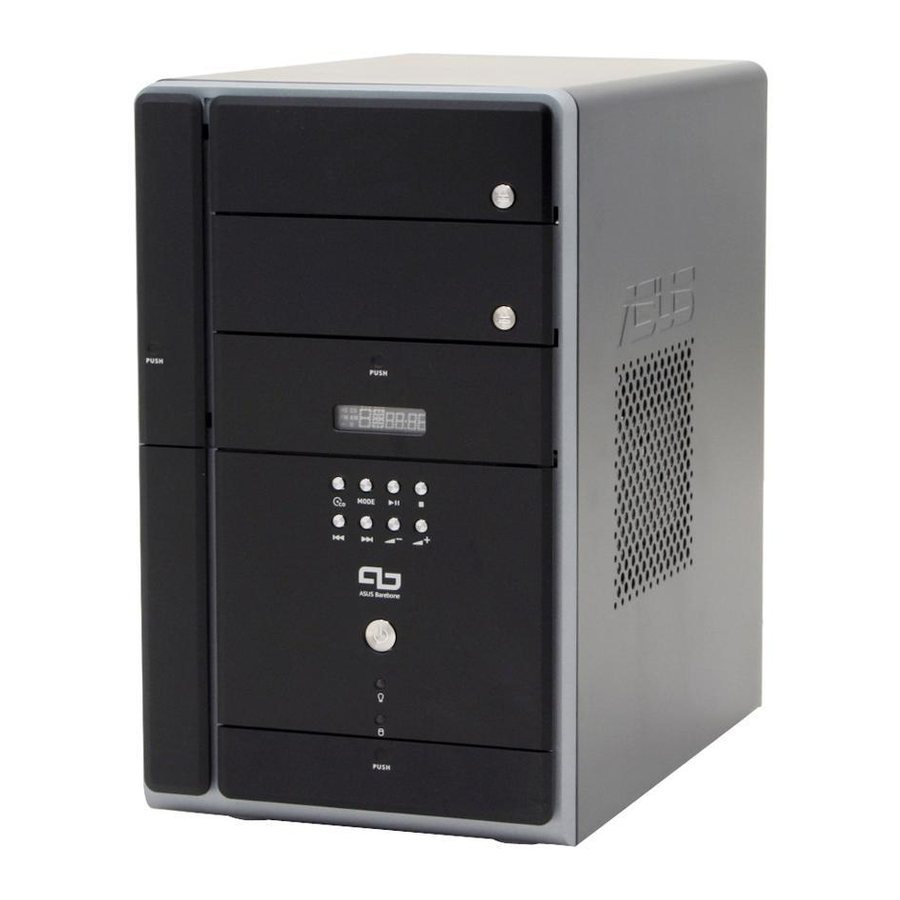
Page 12: Chapter 1: System Introduction
The ASUS T2-PH2 is an all-in-one barebone system with a versatile home entertainment feature. The system comes in a stylish mini-tower casing, and powered by the ASUS motherboard that supports the Intel package with 533/800/1066 MHz FSB and up to 2 GB system memory. - Page 13 In CD mode, plays or pauses an audio CD track. In Radio mode, scans the available FM stations when pressed for less than two seconds or presets a station when pressed for more than two seconds. Refer to page 3-12 on how to preset a radio station. ASUS T2-PH2...
- Page 14 14. STOP button . Press this button to stop the audio track being played. 15. PREVIOUS button different modes. In CD mode, selects the previous audio track. In Radio mode, selects the previous preset station. 16. NEXT button different modes. In CD mode, selects the next audio track.
-
Page 15: Front Panel (Internal)
You cannot close the storage card reader door if a storage card is inserted into any of the card slots. • Use and format a storage card according to the documentation that comes with it. ASUS T2-PH2 MODE 27 28 29 25 26 . This slot is for a... - Page 16 25. Headphone port mini-plug. 26. Microphone port 27. USB 2.0 ports are available for connecting USB 2.0 devices such as a mouse, printer, scanner, camera, PDA, and others. 28. 4-pin IEEE 1394a port connectivity for IEEE 1394a-compliant audio/video devices, storage peripherals, and other PC devices.
-
Page 17: Rear Panel
. This Line Out (lime) port connects a headphone or a speaker. In 4/6-channel mode, the function of this port becomes Front Speaker Out. ASUS T2-PH2 . This green 6-pin connector is for a PS/2 mouse. . This purple 6-pin connector is for a... - Page 18 Microphone port microphone. In 4/6-channel mode, the function of this port becomes Low Frequency Enhanced Output/Center. The functions of the Line Out, Line In, and Microphone ports change when you select the 6-channel configuration. Refer to the table below for audio ports function variation. Audio ports function variation Port Headphone/2-Channel...
-
Page 19: Internal Components
5.25-inch empty optical drive bay Floppy disk drive (optional) Front panel cover Hard disk drive metal tray Chassis fan ASUS motherboard DIMM sockets LGA775 socket with PnP cap 10. PCI slot 11. PCI Express™ x16 slot for discrete graphics card 12. -
Page 20: Led Panel
LED panel The LED panel displays various system information depending on the system mode. The LED panel displays the system time in 24-hour format when the system is in soft-off or stand-by mode, S3 (Suspend-to-RAM), or S4 (Suspend-to-Disk) state. Enter the BIOS setup or the operating system to adjust the time. - Page 21 Chapter 2 This chapter provides step-by-step instructions on how to install components in the system. ASUS T2-PH2...
-
Page 22: Preparation
Preparation Before you proceed, make sure that you have all the components you plan to install in the system. Basic components to install 1. Central Processing Unit (CPU) 2. DDR2 Dual Inline Memory Module (DIMM) 3. Expansion card(s) 4. Hard disk drive 5. -
Page 23: Removing The Cover
Use a Phillips screw driver to remove the cover screws. Keep the screws for later use. Slightly pull the cover toward the rear panel until the side tabs are disengaged from the chassis. Lift the cover, then set aside. ASUS T2-PH2... -
Page 24: Removing The Power Supply
Removing the power supply You must remove the power supply unit (PSU) before you can install a central processing unit (CPU) and other system components. To remove the PSU: Lay the system on its side on a flat, stable surface. Disconnect the optical drive and floppy disk drive power plugs. -
Page 25: Installing A Cpu
Installing a CPU The ASUS motherboard comes with a surface mount LGA775 socket designed for the Intel Pentium ® 2.5.1 Removing the CPU fan and heatsink assembly The system package includes a pre-installed proprietary CPU fan and heatsink assembly to ensure optimum thermal condition and performance. -
Page 26: Cpu Installation
CPU socket and the socket contacts are not bent. Contact your retailer immediately if the PnP cap is missing, or if you see any damage to the PnP cap/socket contacts/motherboard components. ASUS will shoulder the cost of repair only if the damage is shipment/ transit-related. •... - Page 27 Position the CPU over the socket, making sure that the gold triangle is on the bottom-left corner of the socket then fit the socket alignment key into the CPU notch. ASUS T2-PH2 Retention tab Load lever PnP cap Load plate CPU notch...
- Page 28 Apply Thermal Interface Material on the CPU before closing the load plate. DO NOT eat the Thermal Interface Material. If it gets into your eyes or touches your skin, make sure to wash it off immediately, and seek professional medical help. Close the load plate (A), then push the load lever (B) until it snaps into the retention tab.
-
Page 29: Reinstalling The Cpu Fan And Heatsink Assembly
CPU. Drive in the four screws you removed earlier into the CPU fan screw holes to secure the fan and heatsink assembly to the motherboard. Connect the CPU fan cable to the CPU fan connector on the motherboard. ASUS T2-PH2... -
Page 30: Installing A Dimm
Installing a DIMM The system motherboard comes with two Double Data Rate 2 (DDR2) Dual Inline Memory Module (DIMM) sockets. The following figure illustrates the location of the sockets: 240-pin DDR2 DIMM Sockets 2.6.1 Memory configurations You may install up to 2 GB system memory using 256 MB, 512 MB, and 1 GB DDR2 DIMMs. - Page 31 1024 MB MDT 1024 MB 512 MB AENEON AET660UD00-370A98Z 256 MB AENEON AET560UD00-370A98Z 512 MB AENEON AET660UD00-370A98Z 512 MB AENEON AET660UD00-370A98X ASUS T2-PH2 Sockets DIMM_A1 DIMM_B1 — Installed Installed Brand Side/s* Component Elpida Hynix KINGSTON DS SAMSUNG SS SAMSUNG SS Infineon Infineon...
- Page 32 Dual-channel memory configuration. SS - Single-sided DS - Double-sided Obtain DDR DIMMs only from ASUS qualified vendors. Refer to the Qualified DDR2 533/667 vendors list on this page. Visit the ASUS website (www.asus.com) for the latest DDR2 Qualified Vendors List.
-
Page 33: Dimm Installation
DIMM is properly seated. A DDR2 DIMM is keyed with a notch so that it fits in only one direction. DO NOT force a DIMM into a socket to avoid damaging the DIMM! ASUS T2-PH2 Retaining clips 2-13... -
Page 34: Installing An Expansion Card
Installing an expansion card In the future, you may need to install expansion cards. The motherboard has one PCI and one PCI Express™ x16 slot. The following sub-sections describe the slots and the expansion cards that they support. Make sure to unplug the power cord before adding or removing expansion cards. -
Page 35: Expansion Card Installation
Align the card connector with the slot and press firmly until the card is completely seated on the slot. Replace the expansion card lock to secure the card to the chassis. ASUS T2-PH2 Expansion PCI Express card lock x16 slot slot Metal covers... -
Page 36: Irq Assignments For This Motherboard
Standard interrupt assignments * These IRQs are usually available for ISA or PCI devices. IRQ assignments for this motherboard PCI slot PCI Express x16 slot Onboard USB controller 1 Onboard USB controller 2 Onboard USB controller 3 Onboard USB controller 4 Onboard USB 2.0 controller Onboard IDE port Onboard ACʼ... -
Page 37: Installing An Optical Drive
On Deluxe models, disconnect the LED panel and the front audio button panel cables from their respective connectors before removing the front panel cover. To reconnect the cables, see pages 4-12 for the location of the connectors. ASUS T2-PH2 2-17... - Page 38 Carefully push the optical drive into the bay until its screw holes align with the holes on the bay as shown. Secure the optical drive with two screws on one side of the bay. Connect a power cable from the power supply unit to the power connector at the back of the optical drive.
- Page 39 See pages 4-12 for the location of the connectors. 14. Lock the front panel cover hooks to the chassis holes as indicated. ASUS T2-PH2 2-19...
-
Page 40: Installing A Floppy Disk Drive
Installing a floppy disk drive The barebone system comes with one 3.25-inch drive bay for a floppy disk drive. To install a floppy disk drive: Remove the front panel cover. For instructions on how to remove the front panel cover, refer to steps 1-5 of section “2.8 Installing an optical drive”. -
Page 41: Installing A Hard Disk Drive (Hdd)
Configure your hard disk drive as Master device before connecting the IDE cable and power plug. Refer to the HDD documentation on how to set the drive as a Master device. ASUS T2-PH2 Tray locks Lock slots Tray locks... - Page 42 Reinstall the tray and the HDD to the chassis by locking the tray slots to the chassis hooks. Secure the tray with the screw you removed earlier. Connect one end of the 40-pin IDE cable to the IDE connector on the drive. Connect a 4-pin power plug from the power supply unit to the HDD power connector.
- Page 43 15-pin SATA power adapter plug OR the legacy 4-pin power connector. DO NOT use both to prevent damage to components and to keep the system from becoming unstable. ASUS T2-PH2 4-pin (male) power plug 15-pin SATA...
-
Page 44: 2.11 Reinstalling The Power Supply Unit
2.11 Reinstalling the power supply unit Reinstall the power supply unit (PSU) after installing the system components and reconnecting the cables. To reinstall the PSU: Connect the 4-pin 12 V power plug to the ATX12V connector on the motherboard. Connect the 24-pin ATX power plug to the ATXPWR connector on the motherboard. -
Page 45: Voltage Selector
115 V. If the voltage supply in your area is 200-240 V, set the switch to 230 V. Setting the switch to 115 V in a 230 V environment will seriously damage the system! ASUS T2-PH2 - or - 2-25... -
Page 46: 2.12 Replacing The Cover
2.12 Replacing the cover To replace the cover: Turn the chassis upright. Position the front edge of the cover at least two inches from the front panel cover. Fit the cover tabs with the chassis rail and the front panel tabs. Lower the rear edge of the cover as shown. - Page 47 Chapter 3 This chapter helps you power up the system and install drivers and utilities from the support CD. ASUS T2-PH2...
-
Page 48: Chapter 3: Starting Up
Screen display and driver options may not be the same for other operating system versions. • The contents of the support CD are subject to change at any time without notice. Visit the ASUS website for updates. 2000/XP operating systems ® mode, pressing the button shuts down, restarts, or puts ®... -
Page 49: Running The Support Cd
Make sure you install the QFE Update only before installing Microsoft Windows XP Service Pack 1. ® Intel Chipset INF Update Program Installs the Intel Chipset INF Update Program. ® ASUS T2-PH2 Click an icon to display other information ®... -
Page 50: Realtek Audio Driver
Utilities menu The Utilities menu shows the applications and other software that the motherboard supports. ASUS PC Probe II This smart utility continuously monitors vital system information such as fan rotations, CPU temperature, and system voltages, and alerts you on any detected problems. -
Page 51: Asus Update
ASUS Screensaver Bring life to your idle screen by installing the ASUS Screensaver. ASUS Radio Player Installs the ASUS radio application that allows you to tune in to an FM radio station. See page 3-7 for details. Adobe Acrobat Reader V7.0... -
Page 52: Asus Contact Information
3.3.4 ASUS contact information The Contact tab displays the ASUS contact information. 3.3.5 Other information The icons on the top right side of the screen provide additional information on the motherboard and the contents of the support CD. Chapter 3: Starting up... -
Page 53: Software Information
file that came with the software for more information. 3.4.1 ASUS Radio Player ASUS Radio Player allows you to tune in to an FM station using the optional radio module. By default, the radio region of the ASUS FM radio module is set to Europe. -
Page 54: Storing A Radio Station
Storing a radio station To store a radio station: Use the Scan or Tune buttons to tune into a radio station you wish to store. Click the Store button. A Store Channel window appears. Assign a Channel (preset number) to the radio station using the arrow buttons. -
Page 55: Asus Instant Music
• Instant Music only supports PS/2 keyboard. To enable ASUS Instant Music: Connect the analog audio cable from the optical drive to the 4-pin CD connector on the motherboard. See section “4.4 Connectors” for the location of the CD connector. - Page 56 To use ASUS Instant Music: Connect the PC power plug to an electrical outlet. Use either one of the two sets of special function keys on your keyboard to play audio CDs. These keys only function as indicated if you enabled the Instant Music item in BIOS.
-
Page 57: Audio Dj
The station scanning stops when a station is detected. Press the NEXT ( station, if any. ASUS T2-PH2 ) on the front panel to put the system in ) or the PREVIOUS ( ) button to skip to the next... -
Page 58: Presetting A Station
3.5.3 Presetting a station To preset a radio station: Put the Audio DJ in radio mode. Select the radio station you wish to preset by pressing the PLAY/ PAUSE ( / ) button for less than 2 seconds. After selecting the radio station, press the PLAY/PAUSE ( / ) button for more than 2 seconds or until the station frequency display in the LED panel blinks. - Page 59 Chapter 4 This chapter gives information about the motherboard that comes with the system. This chapter includes the motherboard layout, jumper settings, and connector locations. ASUS T2-PH2...
-
Page 60: Introduction
Introduction The ASUS T2-PH2 motherboard comes already installed in the ASUS T2-PH2 system. This chapter provides technical information about the motherboard for future upgrades or system reconfiguration. Motherboard layout IOC_MB PS/2 CPU_FAN T:Mouse B:Keyboard ATX12V VGA1 Line Line ALC655 FP_AUDIO... -
Page 61: Jumpers
6. Hold down the <Del> key during the boot process and enter BIOS setup to re-enter data. Except when clearing the RTC RAM, never remove the cap on CLRTC jumper default position. Removing the cap will cause system boot failure! ® Clear RTC RAM ASUS T2-PH2 CLRTC Normal Clear CMOS (Default) - Page 62 Fan power jumper (3-pin FANPWR1) This jumper allows you to enable or disable the ASUS Q-Fan function. FANPWR1 ® Enable Q-FAN Disable Q-FAN (Default) Fan Power Chapter 3: Starting up...
-
Page 63: Connectors
® Front Panel Audio Connector Digital audio connector (4-1 pin SPDIF_IN) This connector is for the SPDIF_IN connector on the front panel I/O daughterboard to support the front panel S/PDIF In port. ® Digital Audio Connector ASUS T2-PH2 FP_AUDIO SPDIF_IN... - Page 64 CPU and chassis fan connectors (3-pin CPU_FAN, CHA_FAN) The fan connectors support the proprietary CPU fan and chassis fan. Connect the fan cables to the fan connectors on the motherboard, making sure that the black wire of each cable matches the ground pin of the connector.
- Page 65 firmly until the connectors completely fit. ® ATX Power Connectors Do not forget to connect the 4-pin ATX12V power plug to the ATX12V connector on the motherboard; otherwise, the system will not boot up. ASUS T2-PH2 EATXPWR +3 Volts Ground +12 Volts...
- Page 66 IDE connector (40-1 pin PRI_IDE) This connector is for an Ultra DMA 100/66 signal cable. The Ultra DMA 100/66 signal cable has three connectors: a blue connector for the primary IDE connector on the motherboard, a black connector for an Ultra DMA 100/66 IDE slave device (optical drive/hard disk drive), and a gray connector for an Ultra DMA 100/66 IDE master device (hard disk drive).
-
Page 67: Serial Ata Connectors
(boot) hard disk drive to the SATA1 or SATA2 connector. Refer to the table below for the recommended SATA hard disk drive connections. Serial ATA hard disk drive connection Connector SATA1 SATA2 ASUS T2-PH2 SATA1 RSATA_RXN1 RSATA_RXP1 RSATA_TXN1 RSATA_TXP1 SATA2... -
Page 68: Internal Audio Connectors (4-Pin Aux, Cd)
Internal audio connectors (4-pin AUX, CD) These connectors allow you to receive stereo audio input from sound sources such as a CD-ROM, TV tuner, or MPEG card. Internal Audio Connectors Floppy disk drive connector (34-1 pin FLOPPY) This connector is for the provided floppy disk drive (FDD) signal cable. Insert one end of the cable to this connector, then connect the other end to the signal connector at the back of the floppy disk drive. - Page 69 (8-1 pin) on the front panel I/O daughterboard. • Power/Soft-off button This connector is for the system power button connector of the panel connector (8-1 pin) on the front panel I/O daughterboard. ASUS T2-PH2 IEEE 1394 PANEL IEEE 1394 4-11...
-
Page 70: Daughterboard Connectors
Daughterboard connectors USB connector (10-1 pin USB1) Pins 1~5 are for the connector on the storage card reader daughterboard. Front panel daughterboard Storage card reader daughterboard FM radio connector (20-1 pin F_R) This connector links the LED panel, the Adudio DJ Switch, and the FM radio module. - Page 71 ON or puts the system in SLEEP or SOFT-OFF mode depending on the BIOS settings. Pressing the power switch for more than four seconds while the system is ON turns the system OFF. Front panel daughterboard ASUS T2-PH2 PANEL PLED HDLED Requires an ATX power supply.
- Page 72 4-14 Chapter 3: Starting up...
- Page 73 Chapter 5 This chapter tells how to change system settings through the BIOS Setup menus and describes the BIOS parameters. ASUS T2-PH2...
-
Page 74: Managing And Updating Your Bios
The following utilities allow you to manage and update the motherboard Basic Input/Output System (BIOS) setup. ASUS AFUDOS (Updates the BIOS in DOS mode using a bootable floppy disk.) ASUS EZ Flash (Updates the BIOS using a floppy disk during POST.) ASUS CrashFree BIOS 2 (Updates the BIOS using a bootable floppy... -
Page 75: Asus Ez Flash Utility
5.1.2 ASUS EZ Flash utility The ASUS EZ Flash feature allows you to update the BIOS without having to go through the long process of booting from a floppy disk and using a DOS-based utility. The EZ Flash utility is built-in the BIOS chip so it is accessible by pressing <Alt>... -
Page 76: Afudos Utility
5.1.3 AFUDOS utility The AFUDOS utility allows you to update the BIOS file in DOS environment using a bootable floppy disk with the updated BIOS file. This utility also allows you to copy the current BIOS file that you can use as backup when the BIOS fails or gets corrupted during the updating process. -
Page 77: Updating The Bios File
Updating the BIOS file To update the BIOS file using the AFUDOS utility: Visit the ASUS website (www.asus.com) and download the latest BIOS file for the motherboard. Save the BIOS file to a bootable floppy disk. Write the BIOS filename on a piece of paper. You need to type the exact BIOS filename at the DOS prompt. -
Page 78: Asus Crashfree Bios 2 Utility
5.1.4 ASUS CrashFree BIOS 2 utility The ASUS CrashFree BIOS 2 is an auto recovery tool that allows you to restore the BIOS file when it fails or gets corrupted during the updating process. You can update a corrupted BIOS file using the motherboard support CD or the floppy disk that contains the updated BIOS file. -
Page 79: Recovering The Bios From The Support Cd
BIOS file. The utility then updates the corrupted BIOS file. Bad BIOS checksum. Starting BIOS recovery... Checking for floppy... Floppy not found! Checking for CD-ROM... CD-ROM found! Reading file “P5L7T.ROM”. Completed. Start flashing... ASUS T2-PH2... -
Page 80: Asus Update Utility
Visit the ASUS website (www.asus.com) to download the latest BIOS file. 5.1.5 ASUS Update utility The ASUS Update is a utility that allows you to manage, save, and update the motherboard BIOS in Windows allows you to: • Save the current BIOS file •... -
Page 81: Updating The Bios Through The Internet
Updating the BIOS through the Internet To update the BIOS through the Internet: Launch the ASUS Update utility from the Windows Start > Programs > ASUS > ASUSUpdate > ASUSUpdate. The ASUS Update main window appears. Select Update BIOS from... -
Page 82: Updating The Bios Through A Bios File
Updating the BIOS through a BIOS file To update the BIOS through a BIOS file: Launch the ASUS Update utility from the Windows clicking Start > Programs > ASUS > ASUSUpdate > ASUSUpdate. The ASUS Update main window appears. Select Update BIOS from a file option from the drop-down menu, then click Next. -
Page 83: Bios Setup Program
The BIOS setup screens shown in this section are for reference purposes only, and may not exactly match what you see on your screen. • Visit the ASUS website (www.asus.com) to download the latest BIOS file for this motherboard. ASUS T2-PH2 5-11... -
Page 84: Bios Menu Screen
Some of the navigation keys differ from one screen to another. 5-12 Configuration fields [16:37:21] [Wed,10/20/2004] [1.44M, 3.5 in.] [ST320410A] [ASUS CD-S520/A] [Not Detected] [Not Detected] [Not Detected] [Not Detected] General help Use [ENTER], [TAB] or [SHIFT-TAB] to select a field. -
Page 85: Menu Items
[16:37:21] System Date [Wed,10/20/2004] Legacy Diskette A [1.44M, 3.5 in] Primary IDE Master : [ST320410A] Primary IDE Slave : [ASUS CD-S520/A] Third IDE Master : [Not Detected] Third IDE Slave : [Not Detected] Fourth IDE Master : [Not Detected] Fourth IDE Slave : [Not Detected] IDE Configuration... -
Page 86: Main Menu
[360K, 5.25 in.] [1.2M, 5.25in.] [720K, 3.5 in.] [1.44M, 3.5 in.] [2.88M, 3.5 in.] 5-14 [16:37:21] [Wed,10/20/2004] [1.44M, 3.5 in.] :[ST320410A] :[ASUS CD-S520/A] : [Not Detected] : [Not Detected] : [Not Detected] : [Not Detected] Use [ENTER], [TAB] or [SHIFT-TAB] to select a field. -
Page 87: Primary, Third, And Fourth Ide Master/Slave
When set to [Disabled], the data transfer from and to the device occurs one sector at a time. Configuration options: [Disabled] [Auto] ASUS T2-PH2 [Auto] [Auto] [Auto]... -
Page 88: Ide Configuration
PIO Mode [Auto] Selects the PIO mode. Configuration options: [Auto] [0] [1] [2] [3] [4] DMA Mode [Auto] Selects the DMA mode. Configuration options: [Auto] [SWDMA0] [SWDMA1] [SWDMA2] [MWDMA0] [MWDMA1] [MWDMA2] [UDMA0] [UDMA1] [UDMA2] [UDMA3] [UDMA4] [UDMA5] SMART Monitoring [Auto] Sets the Smart Monitoring, Analysis, and Reporting Technology. - Page 89 The Combined Mode Option item appears only when the Onboard IDE Operate Mode is set to [Compatible Mode]. IDE Detect Time Out [35] Selects the time out value for detecting ATA/ATAPI devices. Configuration options: [0] [5] [10] [15] [20] [25] [30] [35] ASUS T2-PH2 5-17...
-
Page 90: System Information
5.3.6 System Information This menu gives you an overview of the general system specifications. The BIOS automatically detects the items in this menu. AMIBIOS Version : 0109 Build Date : 01/19/06 Processor Type : Genuine Intel(R) CPU 3.20 GHz Speed : 3200 MHz Count System Memory... -
Page 91: Advanced Menu
Enables or disables the Instant Music feature. Setting this item to [Enabled] disables the power up by PS/2 keyboard function. Configuration options: [Disabled] [Enabled] When this item is set to [Disabled], the ASUS Audio DJ application can still work. ASUS T2-PH2... -
Page 92: Lan Cable Status
The following items appear when the Instant Music item is set to [Enabled]. Instant Music CD-ROM drive [IDE Primary Slave] Allows you to configure the Instant Music CD-ROM selection. Configuration options: [IDE Primary Master] [IDE Primary Slave] Radio Region [USA] Allows you to select the radio region. -
Page 93: Usb Configuration
Allows you to enable or disable the enhanced host controller interface (EHCI) hand-off support. This is a workaround for operating systems without EHCI hand-off support. The ECHI ownership change should be claimed by the EHCI driver. Configuration options: [Disabled] [Enabled] ASUS T2-PH2 Enables USB host controllers. [Enabled]... -
Page 94: Cpu Configuration
5.4.4 CPU Configuration The items in this menu show the CPU-related information that the BIOS automatically detects. Configure advanced CPU Settings Manufacturer : Intel Brand String : Genuine Intel(R) CPU 3.20 GHz Frequency : 3200 MHz FSB Speed 800 MHz Cache L1 : 16 KB Cache L2... - Page 95 Configuration options: [Auto] [Disabled] CPU Internal Thermal Control [Auto] Disables or sets the CPU internal thermal control. Configuration options: [Auto] [Disabled] Hyper Threading Technology [Enabled] Enables or disables the processor Hyper-Threading Technology. Configuration options: [Disabled] [Enabled] ASUS T2-PH2 5-23...
-
Page 96: Chipset
5.4.5 Chipset The Chipset menu allows you to change the advanced chipset settings. Select an item then press <Enter> to display the sub-menu. Advanced Chipset Settings Configure DRAM Timing by SPD Graphic Adapter Priority Internal Graphics Mode Select Graphic Memory Type Configure DRAM Timing by SPD [Enabled] When this item is enabled, the DRAM timing parameters are set according to the DRAM SPD (Serial Presence Detect). -
Page 97: Internal Graphics Mode Select [Enabled, 8Mb]
Internal Graphics Mode Select item to [DVMT]. • When you set the item Internal Graphics Mode Select to [DVMT + FIX], both the Fixed Graphic Memory Size and DVMT Graphic Memory Size items appear without configuration options. ASUS T2-PH2 5-25... -
Page 98: Onboard Devices Configuration
5.4.6 Onboard Devices Configuration Configure Win627EHG Super IO Chipset AC’97 Controller Onboard 1394 Controller Onboard PCIEX GbE LAN LAN Option ROM Serial Port1 Address Parallel Port Address Parallel Port Mode ECP Mode DMA Channel Parallel Port IRQ Onboard Game/MIDI Port ACʼ97 Controller [Enabled] Enables or disables the ACʼ97 CODEC. -
Page 99: Parallel Port Address
Allows selection of the Parallel Port EPP version. This item appears only when the Parallel Port Mode is set to EPP. Configuration options: [1.9] [1.7] Parallel Port IRQ [IRQ7] Allows selection of the Parallel Port IRQ. Configuration options: [IRQ5] [IRQ7] ASUS T2-PH2 5-27... -
Page 100: Pci Pnp
5.4.7 PCI PnP The PCI PnP menu items allow you to change the advanced settings for PCI/PnP devices. The menu includes setting IRQ and DMA channel resources for either PCI/PnP or legacy ISA devices, and setting the memory size block for legacy ISA devices. - Page 101 IRQ-xx assigned to [PCI Device] When set to [PCI Device], the specific IRQ is free for use of PCI/PnP devices. When set to [Reserved], the IRQ is reserved for legacy ISA devices. Configuration options: [PCI Device] [Reserved] ASUS T2-PH2 5-29...
-
Page 102: Power Menu
Power menu The Power menu items allow you to change the settings for the ACPI and Advanced Power Management (APM). Select an item then press <Enter> to display the configuration options. Suspend Mode ACPI 2.0 Support ACPI APIC Support APM Configuration Hardware Monitor 5.5.1 Suspend Mode [Auto]... -
Page 103: Apm Configuration
Thus, connection cannot be made on the first try. Turning an external modem off and then back on while the computer is off causes an initialization string that turns the system on. ASUS T2-PH2 Go into On/Off or Suspend when Power [On/Off] button is pressed. - Page 104 Power On By PCI Devices [Disabled] Power On By PCIE Devices [Disabled] When set to [Enabled], this parameter allows you to turn on the system through a PCI LAN, modem card, or PCI Express device. This feature requires an ATX power supply that provides at least 1A on the +5VSB lead. Configuration options: [Disabled] [Enabled] Power On By PS/2 Keyboard [Disabled] Allows you to use specific keys on the keyboard to turn on the system.
-
Page 105: Hardware Monitor
field shows N/A. CPU Q-Fan Control [Enabled] Allows you to enable or disable the ASUS Q-Fan feature that smartly adjusts the fan speeds for more efficient system operation. When this field is set to [Enabled], the three succeeding items appear. Configuration... -
Page 106: Boot Menu
Boot menu The Boot menu items allow you to change the system boot options. Select an item then press <Enter> to display the sub-menu. Boot Settings Boot Device Priority Boot Settings Configuration Security 5.6.1 Boot Device Priority Boot Device Priority 1st Boot Device 2nd Boot Device 3rd Boot Device... -
Page 107: Boot Settings Configuration
This allows you to enable or disable the full screen logo display feature. Configuration options: [Disabled] [Enabled] Set this item to [Enabled] to use the ASUS MyLogo2™ feature. Add On ROM Display Mode [Force BIOS] Sets the display mode for option ROM. -
Page 108: Interrupt 19 Capture [Disabled]
Hit ʻDELʼ Message Display [Enabled] When set to Enabled, the system displays the message “Press DEL to run Setup” during POST. Configuration options: [Disabled] [Enabled] Interrupt 19 Capture [Disabled] When set to [Enabled], this function allows the option ROMs to trap Interrupt 19. -
Page 109: Change User Password
Select the Change User Password item and press <Enter>. On the password box that appears, type a password composed of at least six letters and/or numbers, then press <Enter>. Confirm the password when prompted. ASUS T2-PH2 <Enter> to change password. <Enter> again to disabled password. -
Page 110: Clear User Password
The message “Password Installed” appears after you set your password successfully. To change the user password, follow the same steps as in setting a user password. Clear User Password Select this item to clear the user password. Password Check [Setup] When set to [Setup], BIOS checks for user password when accessing the Setup utility. -
Page 111: Discard Changes
Setup menus. When you select this option or if you press <F5>, a confirmation window appears. Select OK to load default values. Select Exit & Save Changes or make other changes before saving the values to the non-volatile RAM. ASUS T2-PH2 5-39... - Page 112 5-40 Chapter 5: BIOS setup...
-
Page 113: Appendix
Appendix The Appendix includes the power supply unit specification for this system. ASUS T2-PH2... -
Page 114: Output Characteristics
Power supply specifications Input characteristics Input Voltage Range Range 1 Range 2 Input Frequency Range Maximum Input AC Current Inrush Current Efficiency Current Harmonic Output characteristics Output Load Range Voltage +5 V 1.5 A +12 V 0.5 A -12 V 0.05 A +3.3 V 0.3 A...
Need help?
Do you have a question about the Barebone System T2-PH2 and is the answer not in the manual?
Questions and answers