Advertisement
Quick Links
Advertisement

Related Manuals for Ripmax Dagger


Summary of Contents for Ripmax Dagger
- Page 1 Part Number: A-ARTF6906 INSTRUCTION MANUAL Bestellnummer: A-ARTF6906 BAUANLEITUNG...
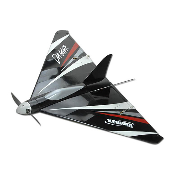
- Page 2 R/C. Designed for mini servos (we used Ripmax SD200s on the prototypes) and a choice of 3 or 4S Li-Pos, the Dagger has a fantastic turn of speed, yet is almost impossible to stall. A vice-free performer, the Dagger is simple to launch with handy finger grips on the underside.
- Page 3 STEP / SCHRITT 1 The wings and elevons are supplied with the hinges loose fitted, ready for installation. Remove both elevons and ensure that the hinges are inserted midway in their slots. Using thin cyano, pour a couple of drops onto each hinge - above and below - ensuring the glue soaks into the hinge and the surrounding wood.
- Page 4 STEP / SCHRITT 4 Epoxy the servo mounting blocks in place as shown. Ensure that the servo output arms are centred over the exits. Kleben Sie die Servo Einbaublöcke an ihren Platz fest, wie gezeigt. Beachten Sie, dass die Servoarme mittig in den Ausgängen sitzen.
- Page 5 STEP / SCHRITT 8 Screw the elevon horns into place, with the self tapping screws threading into the hardwood plates in the elevon. Schrauben Sie die Querruder Hörner mit den selbstschneidenden Schrauben in die Hartholzplatten im Querruder. STEP / SCHRITT 9 With the pushrod connected to its horn, mark the position the control rod passes over the servo’s output arm.
- Page 6 STEP / SCHRITT 12 Remove the covering film within the cut lines then glue the skids into place. Entfernen Sie die Folie an der Schnittlinie, und kleben die Kufen an ihren Platz. STEP / SCHRITT 13 Using one hour epoxy spread this inside the front and rear spar pockets on one wing panel.
- Page 7 STEP / SCHRITT 16 Use masking tape to hold the wing panels securely against the fuselage sides until the epoxy has cured, whilst checking that the panels are aligned with each other, and are square to the fuselage. Mit Abdeckband sichern Sie jetzt die Flügelhälften am Rumpf, bis der Epoxid ausgehärtet ist.
- Page 8 STEP / SCHRITT 20 Offer the fins into position on the wing/fuselage joint, then carefully cut through the covering film on the wing/fuselage. Finden Sie die Aussparung für die Finnen auf den Oberseiten der Flügel, und schneiden vorsichtig die Folie an diesen Positionen aus, damit die Finnen befestigt werden können.
- Page 9 STEP / SCHRITT 24 Fit the propeller adapter, propeller and supplied spinner. Befestigen Sie den Propeller Adapter, Propeller und den mitgelieferten Spinner. STEP / SCHRITT 25 Install the ESC being used and connect to the motor. The battery being used is retained with hook and loop tape, but will also required packing to hold it in the correct position to obtain the required balance point, small balsa packing pieces...
- Page 10 CONTROL THROWS / RUDERAUSSCHLAGE Control Throws: The control surface movements should be set as follows for first flights; Roll (aileron function) Low rate: 6mm each way at trailing edge of elevon – use 60% exponential. High rate: 12mm each way at trailing edge of elevon – use 60% exponential. Pitch (elevator function) 10mm each way –...
- Page 11 ¾ power at first until experience is gained. It is recommended that low rate roll (aileron) is used on the first launch, as high rate gives a spectacular roll rate! The Dagger is very smooth to fly at all flying speeds, and at high speed will track beautifully, even through turbulence, whilst slow speeds show off the delta’s advantages,...
- Page 12 In no case shall Ripmax’s liability exceed the original cost of the purchased kit. In that Ripmax has no control over the final use, no liability shall be assumed or accepted for any damage resulting from the use of the product by the user.