Table of Contents
Advertisement
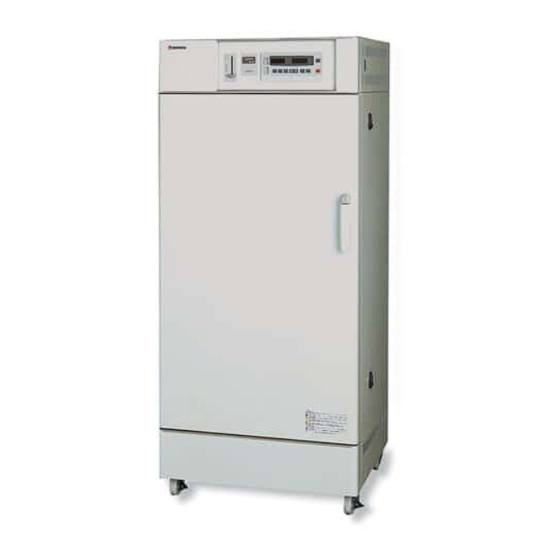
Forced Convection
Constant Temperature Oven
Model
DNF 400/410/600
610/810/910
Instruction Manual
- Version 5 -
Thank you for purchasing "Forced Convection
Constant Temperature Oven, DNF Series" of
Yamato Scientific Co., Ltd.
To use this unit properly, read this "Instruction
Manual" thoroughly before using this unit.
Keep this instruction manual around this unit for
referring at anytime.
WARNING!:
Carefully read and thoroughly understand the
important warning items described in this
manual before using this unit.
Yamato Scientific Co. LTD.
Advertisement
Table of Contents

Subscribe to Our Youtube Channel
Related Manuals for Yamato DNF 400


Summary of Contents for Yamato DNF 400
- Page 1 - Version 5 - Thank you for purchasing "Forced Convection Constant Temperature Oven, DNF Series" of Yamato Scientific Co., Ltd. To use this unit properly, read this "Instruction Manual" thoroughly before using this unit. Keep this instruction manual around this unit for referring at anytime.
-
Page 3: Table Of Contents
Contents Cautions in Using with Safety..............1 • Explanation........................1 • Table of Illustrated Symbols ..................2 • Fundamental Matters of "WARNING!" and "CAUTION!" ..........3 Before Using this unit ................4 • Requirements for Installation..................4 Description and Function of Each Part ..........9 •... - Page 4 Handling Precautions ................56 Maintenance Method................57 • Daily Inspection and Maintenance ................57 Long storage and disposal..............58 • When not using this unit for long term / When disposing ..........58 In the Event of Failure… ............... 59 •...
-
Page 5: Cautions In Using With Safety
Cautions in Using with Safety Explanation MEANING OF ILLUSTRATED SYMBOLS Illustrated Symbols Various symbols are used in this safety manual in order to use the unit without danger of injury and damage of the unit. A list of problems caused by ignoring the warnings and improper handling is divided as shown below.Be sure that you understand the warnings and cautions in this manual before operating the unit. -
Page 6: Table Of Illustrated Symbols
Cautions in Using with Safety Table of Illustrated Symbols Warning Warning, Warning, Warning, Warning, Warning, generally high voltage high temperature drive train explosive Caution Caution, Caution, Caution, Caution, Caution, generally electrical shock scald no road heating not to drench Caution, Caution, water only deadly poison... -
Page 7: Fundamental Matters Of "Warning!" And "Caution
Cautions in Using with Safety Fundamental Matters of "WARNING!" and "CAUTION!" WARNING! Do not use this unit in an area where there is flammable or explosive gas Never use this unit in an area where there is flammable or explosive gas. This unit is not explosion-proof. -
Page 8: Before Using This Unit
Before Using this unit Requirements for Installation WARNING! 1. Always ground this unit • The DNF400 and DNF600 types use a 100V power source. • The DNF600 type does not contain a power plug. Please consult your local electrical contractor for power connecting work. •... - Page 9 Before Using this unit Requirements for Installation 3. Do not use this unit in an area where there is flammable or explosive gas (Refer to page 71 "List of Dangerous Substances".) • Never use this unit in an area where there is flammable or explosive gas. This unit is not explosion-proof.
- Page 10 Before Using this unit Requirements for Installation 4. Do not modify 5. Installation on horizontal surface • Modification of this unit is strictly • Set this unit to the flattest place. Setting prohibited. This could cause a failure. this unit on rough or slope place could cause the vibration or noise, or cause the unexpectible trouble or malfunction.
- Page 11 Before Using this unit Requirements for Installation 8. Do not use corrosive sample • Stainless steel SUS304 is used for the main hot-air path; however, it may be corroded by strong acid etc. And the door packing made of silicon rubber may be corroded by some kind of solvent, e.g.
- Page 12 Before Using this unit Requirements for Installation 12. Setting of the shelf and sample • The number of shelves attached varies depending on the type of product (2 to 8).One of them (two for DNF910) is previously fixed on the lowermost stand of bracket supporter with screws at factory shipment.
-
Page 13: Description And Function Of Each Part
Description and Function of Each Part Main Unit DNF400/410/600/610 Front view Production plate Cable port Door Shelf Door handle Intake opening Specification plate Damper knob Earth leakage breaker Overheating prevention device Control panel Rear view Exhaust opening Optional accessory attaching port Power code (DNF410/600/610) Power code... - Page 14 Description and Function of Each Part Main Unit DNF810 Front view Control panel Overheating prevention device Earth leakage breaker Production plate Cable port Damper knob Door Intake opening Door handle Specification plate Rear view Optional accessory attaching port Exhaust opening Power code...
- Page 15 Description and Function of Each Part Main Unit DNF910 Front view Control panel Overheating prevention device Earth leakage breaker Production plate Damper knob Cable port Door handle Intake opening Door Specification plate Rear view Optional accessory attaching port Exhaust opening Power code Exhaust opening...
-
Page 16: Control Panel
Description and Function of Each Part Control Panel FIXED TEMP DOOR AUTO STOP ℃ SUBMENU AUTO START TROUBLE PROGRAM STANDBY POWER HEATER FUNCTION PROGRAM MENU ENTER CANCEL Displays the measured temperature and error code. Main Display: Displays the operation and setting information. Sub Display:... -
Page 17: Operation Method
Operation Method Key Operation Chart of Mode Setting and Program Registering... -
Page 18: Operation Mode And Function List
Operation Method Operation Mode and Function List The operation mode consists of the following four modes. Name Description Page Controls temperature with fixed temperature. Fixed Temperature Operation Stops operation at specified time. Auto Stop Operation Starts operation at specified time. Auto Start Operation Starts program operation at specified time. -
Page 19: Fixed Temperature Operation
Operation Method Fixed Temperature Operation Start the operation from turning on the power shown in the figure, and continue the operation under the setting temperature unless turning off the power. SV: Setting temperature t: Time ▲ ▲ STOP START Setting of the Fixed Temperature Operation Turn on the power •... - Page 20 Operation Method Fixed Temperature Operation Set temperature ① The setting temperature input screen displayed. The Sub Display indicates "Set TEMP" and the numeric character that indicates FIXED TEMP DOOR Set TEMP 0℃ AUTO STOP SUBMENU ℃ AUTO START Fixed TEMP OPR temperature blinks.
-
Page 21: Auto Stop Operation
Operation Method Auto Stop Operation As shown in the following figure, the device stops operating automatically by setting the timer. Set timer ▼ SV: Setting temperature t: Time Waiting Operation period Activate timer Start operation (manual) Stop operation (auto) Setting of the Auto Stop Operation Turn on the power •... - Page 22 Operation Method Auto Stop Operation Set temperature, operation period/stop ① The setting temperature input screen time, and fan displayed. The Sub Display indicates "Set TEMP" and the numeric character that indicates temperature blinks. FIXED TEMP DOOR Set TEMP 0℃ AUTO STOP SUBMENU ℃...
- Page 23 Operation Method Auto Stop Operation Start operation ① Press the ENTER key to decide the setting and the auto stop operation starts. The blinking AUTO STOP lamp lights on and the Sub Display FIXED TEMP DOOR Set TEMP 100℃↑ AUTO STOP SUBMENU ℃...
-
Page 24: Auto Start Operation
Operation Method Auto Start Operation As shown in the following figure, this mode is applied to the device for starting the operation after the specified time (hours) automatically. Note that the device does not stop the operation automatically. Stop the operation by manual without fail. SV: Setting temperature Set timer t: Time... - Page 25 Operation Method Auto Start Operation Set temperature and start wait period/time ① The setting temperature input screen displayed. The Sub Display indicates "Set TEMP" and the numeric character that indicates FIXED TEMP DOOR Set TEMP 0℃ AUTO STOP SUBMENU ℃ AUTO START Auto-start OPR temperature blinks.
-
Page 26: Program Operation
Operation Method Program Operation As shown in the figure, this mode is used for running the device under the setting program. Start pv (Temperature) Setting temperature Step1 Step2 Step3 Step4 Step5 Step6 Step7 Step8 (Time) Start program End program Setting of the Program Operation Turn on the power •... - Page 27 Operation Method Program Operation Set step number and start wait period/ ① The initiating step input screen is displayed. time The Sub Display displays "First step" and the step number blinks. FIXED TEMP DOOR ② Select the step number using the"▼▲" and then First step AUTO STOP SUBMENU...
- Page 28 Operation Method Program Operation Start operation ① Press the ENTER key to decide the operation start wait period/time. The unit enters to program operation wait state. The blinking FIXED TEMP DOOR Step AUTO STOP SUBMENU ℃ PROGRAM lamp lights on and the STANDBY AUTO START Start in 30min...
-
Page 29: Input Program
Operation Method Input Program Select program function ① Press the PROGRAM key. The program menu • Check that the power in turned on. starts and step number selection screen is displayed. Press the "▼▲". The registered step numbers PROGRAM and the smallest number of un-used step are displayed in sequence. - Page 30 Operation Method Input Program Edit step Item Sub Display Notes Delete the step currently referred to. Delete step sequence number of each step hereafter Step deletion decreases by one. Program End Complete program registration/edition. Program end The step number currently edited is displayed on the lower column of Sub Display. The details for all registered steps in use are displayed followed by all un-used steps.
-
Page 31: Input Program; Set The Temperature
Operation Method Input Program; Set the Temperature Temperature setting procedure ① Select the "Set TEMP" and press the ENTER key. The temperature setting edition screen is displayed. The blinking "" (cursor) goes out and the setting value blinks instead. Set TEMP Set TEMP ►... -
Page 32: Input Program; Set The Time
Operation Method Input Program; Set the Time Time setting procedure ① Select the "Set time" and press the ENTER key. The time setting edition screen is displayed. The blinking "" (cursor) goes out and the setting value blinks instead. Set time ►... -
Page 33: Input Program; Set The Fan Rotation Speed
Operation Method Input Program; Set the Fan Rotation Speed Fan rotation speed setting procedure ① Select the "Fan" and press the ENTER key. The setting edition screen is displayed. blinking "" (cursor) goes out and the setting value blinks instead. ►... -
Page 34: Input Program; Set The Repeat Initiating Step
Operation Method Input Program; Set the Repeat Initiating Step Repeat initiating step setting procedure ① Select the "Rep. start" and press the ENTER key. The setting edition screen is displayed. The blinking "" (cursor) goes out and the setting value blinks instead. Rep. -
Page 35: Input Program; Set The Repeat Count
Operation Method Input Program; Set the Repeat Count Repeat count setting procedure ① Select the "Rep. count" and press the ENTER key. The setting edition screen is displayed. The blinking "" (cursor) goes out and the setting value blinks instead. Rep. -
Page 36: Input Program; Insert Step
Operation Method Input Program; Insert Step Step insertion procedure ① Select the "Insert step" and then press the ENTER key. A step is added there. Set TEMP Insert step ►0℃ ENTER → (Selection screen) (Selection screen for step inserted) The newly added step is inserted into the step number which is displayed on the selection screen. The sequence number of each registered step hereafter increases according to the number of steps added. -
Page 37: Input Program; Add Step
Operation Method Input Program; Add Step Step addition procedure ① Display the setting of un-used step on the setting item selection screen and then press the ENTER key. DOOR Set TEMP 0℃ S23(un-used) TROUBLE ENTER CANCEL The "SO1" (the first step) indicates "un-used" at the first registration of program. The items other than "Insert step", "Delete step"... -
Page 38: Input Program; Delete Step
Operation Method Input Program; Delete Step Step deletion procedure ① Press the program key. The program menu starts and step number selection screen is displayed. Press the "▼▲". The registered step numbers and the smallest number of un-used step are displayed in sequence. -
Page 39: Input Program; End Program
Operation Method Input Program; End Program End program procedure ① Select the "Program End" and press the ENTER key. The program edition is completed. DOOR Program End Standby TROUBLE → 2002/01/01 12:00 ENTER CANCEL ② The program edition has not done if the POWER or CANCEL key is pressed before pressing the "Program End"... -
Page 40: Program Creation Method
Operation Method Program Creation Method The program pattern below is explained as an example. - Program pattern example - Temp 200℃ 100℃ 0℃ Step Temp.(℃) Time(min.) 2:30 ← Repeat function → Repeat the steps S01 to S07 once Fan speed Rep. - Page 41 Operation Method Program Creation Method Edit step • The unit operates with fixed rate inclination if the "START TEMP" and the "Set Temp" are different. It enters into "Wait" if the temperature does not reach to the setting temperature within a setting time.
- Page 42 Operation Method Program Creation Method Edit step • Refer to the page 55 for the temperature rise/fall time. They vary depending on the sample used or condition of exhaust opening (open or close). Check them by conducting operation. • The conception of repeat is shown in the figure below. The first operation of repeat interval is not counted as a repeat count.
- Page 43 Operation Method Program Creation Method Program creation; Step 1 (S01) ⑥ Press the PROGRAM key. The fan rotation speed ► 10 selection screen is displayed. ⑦ Press the ENTER key. The fan rotation speed edition screen is displayed. Set "10" using the "▼▲" and press the ENTER key to decide it.
- Page 44 Operation Method Program Creation Method Program creation; Step 3 (S03) to Step 7 (S07) ① Keep pressing the PROGRAM key until "SteP 3" (S03) is Set TEMP ► 0℃ displayed. S03(un-used) ② Edit in the same way to Step 6 (S06) and then keep DOOR Set TEMP pressing the PROGRAM key until the Step 7 (S07) is...
- Page 45 Operation Method Program Creation Method Program creation; Step 8 (S08) to Step 9 (S09) ① Keep pressing the PROGRAM key until "SteP 8" (S08) is displayed. DOOR Set TEMP 0 ℃ ② Edit in the same way for Step 8 (S08). S09(un-used) TROUBLE ③...
-
Page 46: Programming Preparation Form
Operation Method Programming Preparation Form (Please use this form by making copies) -
Page 47: Set The Timer Mode
Operation Method Set the Timer Mode Changes in timer mode are not reflected in the operation currently carried out in the following state of unit; operation start waiting state in the auto start mode, during auto stop mode operation, and operation start waiting state in the program operation mode. -
Page 48: Set The Key Lock Mode
Operation Method Set the Key Lock Mode Select the item in function menu • Check that the power in turned on. ① Press the FUNCTION key. The function menu starts and the Sub Display displays the items. FUNCTION Select the item using the FUNCTION key. ②... -
Page 49: Set The Buzzer Mode
Operation Method Set the Buzzer Mode Select the item in function menu • Check that the power in turned on. ① Press the FUNCTION key. The function menu starts and the Sub Display displays the items. FUNCTION Select the item using the FUNCTION key. ②... -
Page 50: Calibration Offset Function
Operation Method Calibration Offset Function Calibration offset is a function which corrects the difference between the temperature in furnace and that of controller (sensor temperature) if arises. The function parallel corrects the difference either to the plus or minus side within the whole temperature range of unit. 210℃... -
Page 51: Integrating Operation Time
Operation Method Integrating Operation Time The integrating operation time is a function to check the operation hours of unit. Its content can not be changed. Select the item in function menu • Check that the power in turned on. ① Press the FUNCTION key. The function menu starts and the Sub Display displays the items. -
Page 52: Set Clock
Operation Method Set Clock The clock is not set at factory shipment. Set it with your watch or time tone before using the unit. The setting for clock can not be changed at the operation start waiting state in the auto start mode/program mode, or during operation. - Page 53 Operation Method Set Clock Input value ① The "" (cursor) goes out and the current value Date 2001/09/22 blinks instead. Display the desired value using Time 17:30 the "▼▲". ↓ Date 2002/09/22 Time 17:30 Set clock ① Press the ENTER key. The setting is decided and the function menu selection screen is DOOR Date...
-
Page 54: Set Fan Operation At Wait State
Operation Method Set Fan Operation at Wait State Select the item in function menu • Check that the power in turned on. ① Press the FUNCTION key. The function menu starts and the Sub Display displays the items. FUNCTION Select the item using the FUNCTION key. ②... -
Page 55: Set The Fan Rotation Speed
Operation Method Set the Fan Rotation Speed The setting value of fan rotation in each operation mode is displayed in the following three conditions. They, however, can not be changed. ・Operation completed state in auto stop mode, and the fan function parameter is set to "OFF". ・During operation or operation completed state in program operation mode. -
Page 56: Set The Communication Lockout Mode (Optional Accessory)
Operation Method Set the Communication Lockout Mode (Optional accessory) Select the item in function menu • Check that the power in turned on. ① Press the FUNCTION key. The function menu starts and the Sub Display displays the items. FUNCTION Select the item using the FUNCTION key. -
Page 57: How To Operate The Damper
Operation Method How to Operate the Damper Adjust the ventilation level by shifting the damper knob up or down. • Closing the damper reduces the temperature rising time and saves electricity. We recommend setting the damper knob at 0 unless using for ventilation or shortening the time Full opened for the temperature to fall. -
Page 58: The Independent Overheating Prevention Device
Operation Method The Independent Overheating Prevention Device Select the item in function menu ① Set the temperature using the "▼▲". ℃ Notes for the independent overheating prevention device • In case there is a small difference between the set values of temperature for the independent overheating prevention device and that of controller, the independent overheating prevention device may be activated and stops the operation. -
Page 59: Temperature Rise/Fall Data (Reference Data)
Operation Method Temperature Rise/Fall Data (Reference Data) The temperature rise/fall data show the reference value when the unit is operated without load. The program should be created based on the data collected by operating the unit with samples put there. Temperature rise data ℃... -
Page 60: Handling Precautions
Handling Precautions WARNING! If a problem occurs If smoke or strange odor should come out of this unit for some reason, turn off the power key right away, and then turn off the circuit breaker and the main power. Immediately contact a service technician for inspection. -
Page 61: Maintenance Method
Maintenance Method Daily Inspection and Maintenance WARNING! • Disconnect the power cable from the power source when doing an inspection or maintenance unless needed. • Perform the daily inspection and maintenance after returning the temperature of this unit to the normal one. -
Page 62: Long Storage And Disposal
Long storage and disposal When not using this unit for long term / When disposing CAUTION! When not using this unit for long term… • Turn off the power and disconnect the power cord. WARNING! When disposing… • Keep out of reach of children. •... -
Page 63: In The Event Of Failure
In the Event of Failure… Safety Device and Error Code This unit has an automatic diagnosis function built in the controller and safety devices independent of the controller. The following table shows the purpose, operation and corrective actions against error of safety devices. - Page 64 In the Event of Failure… Safety Device and Error Code Safety Device Purpose State Display Cause/Solution TROUBLE lamp blinks • Failure in main relay. To notice Main relay • Alarm buzzer impossibility of Check the cause by trouble heater circuit shut activated contacting detection...
-
Page 65: Trouble Shooting
In the Event of Failure… Trouble Shooting Refer to page 59 "Safety Device and Error Code" for the state of unit at activation of safety device and corrective actions. Problem Possible Cause Solution Check power connection and The sub indicator does not Power is not supplied. -
Page 66: After Service And Warranty
In Case of Request for Repair If the failure occurs, stop the operation, turn OFF the power switch, and unplug the power plug. Please contact the sales agency that this unit was purchased, or the Yamato Scientific's sales office. < Check following items before contact >... -
Page 67: Specification
Specification DNF400/410 DNF600/610 DNF810 DNF910 Method Wind velocity adjustable / Forced circulation (with exhaust damper) Temperature control Room temp.+ 5℃ to 260℃ range Temperature ±0.5℃ (at 260℃) adjustment accuracy Temperature ±2.5℃ (at 260℃) distribution accuracy Time required to reach Approx. 75min. Approx. - Page 68 Specification DNF400/410 DNF600/610 DNF810 DNF910 Capacity 150L 300L 540L Withstand load 15kg/one shelf of shelf Number of shelf bracket step Interval of 30mm shelf bracket steps DNF400: DNF600: 100V AC, 13.5A 100V AC, 16A Power supply 200V AC, 15A 200V AC, 18A DNF410: DNF610: (50/60Hz)
-
Page 69: Wiring Diagram
Wiring Diagram DNF400/600 ① AC100V ② ⑦ ⑧ ③ ④ ⑨ ⑪ ⑩ ⑫ ⑬ ⑰ 2 CN3 ⑱ CONT Symbol Part name Symbol Part name Earth leakage breaker Triac Fan motor Independent overheating prevention device Heater Current transformer Terminal block TH1/TH2 Temperature sensor (K thermocouple) Transformer... - Page 70 Wiring Diagram DNF410/610 ① AC200V ② ⑦ ⑧ ③ ④ ⑨ ⑪ ⑩ ⑫ ⑬ ⑰ 2 CN3 ⑱ CONT Symbol Part name Symbol Part name Earth leakage breaker Triac Fan motor Independent overheating prevention device Heater Current transformer Terminal block TH1/TH2 Temperature sensor (K thermocouple) Transformer...
- Page 71 Wiring Diagram DNF810 ① AC200V ② ⑧ ③ ④ ⑨ ⑦ ⑪ ⑩ ⑫ ⑤ ⑬ ⑰ 2 CN3 ⑥ ⑱ 2 3 4 5 CONT Symbol Part name Symbol Part name Earth leakage breaker Triac Fan motor Independent overheating prevention device H1/H2 Heater Current transformer...
- Page 72 Wiring Diagram DNF910 ① AC200V ⑲ ② ⑪ ③ SSR1 ④ SSR2 ⑫ ⑭ ⑬ ⑤ ⑮ ⑯ ⑥ ⑦ 2 CN3 CONT FG N ⑧ ⑨ 2 CN3 ② Symbol Part name Symbol Part name Earth leakage breaker SSR1/SSR2 Triac FM1/FM2 Fan motor...
-
Page 73: Replacement Parts Table
Common parts Symbol Part Name Code No. Specification Manufacturer X1/X2 Relay 2-05-000-0013 AHN36006 Matsushita Independent overheating 2-10-011-0002 PAS3K1-0YB0Y Yamato Scientific prevention device Current transformer 2-17-001-0002 CTL-6-S-400 Temperature sensor TH1/TH2 1-16-003-0054 LCK-M1-2000-M Yamato Scientific (K thermocouple) CONT PLANAR board 1-24-000-0108 IV CR2... - Page 74 Replacement Parts Table DNF600 Symbol Part Name Code No. Specification Manufacturer Earth leakage breaker 2-06-005-0002 BJS2032N Matsushita Heater DNF60-30020 100V 1.5kW Yamato Scientific Transformer 2-18-000-0040 ⅣCR2 100V Yamato Scientific Terminal block 2-07-023-0001 MO11-0FX 4P TOYO LT00028423 SSR-01 Yamato Scientific Power cord 2-13-001-0010...
-
Page 75: Reference
Reference List of Dangerous Substances Never use explosive substances, flammable substances and substances that include explosive or flammable ingredients in this unit. EXPLOSIVE Ethylene glycol dinitrate (nitro glycol), Glycerin trinitrate (nitroglycerine), Cellulose nitrate (nitrocellulose), and other explosive nitrate esters Trinitrobenzene, Trinitrotoluene, Trinitrophenol (picric acid), and other explosive EXPLOSIVE: nitro compounds Acetyl hidroperoxide (peracetic acid), Methyl ethyl ketone peroxide, Benzyl... - Page 76 Responsibility Please follow the instructions in this document when using this unit. Yamato Scientific has no responsibility for the accidents or breakdown of device if it is used with a failure to comply. Never conduct what this document forbids. Unexpected accidents or breakdown may result in.
Need help?
Do you have a question about the DNF 400 and is the answer not in the manual?
Questions and answers